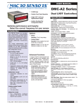
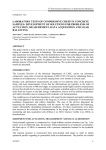
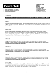
1
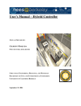
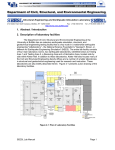
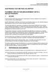
Model 6013/6014
4-3
6015 JUNCTION BOX
The 6084 Junction Box is
thermocouples and other inputs.
for
terminating
The interior of the thermocouple junction box must be
at a uniform temperature to minimize temperature
differential between the thermocouple connections
and the temperature sensor. Therefore, it is important
that the cover be installed after connections are made
and that the grommet through which the cables enter
be sealed. It is also recommended that the junction
box be placed in a location that has the lowest
temperature variation. If temperature variations are
extreme, the junction box may be filled with Styrofoam
or similar insulating material to reduce air movement.
6084 Junction Box
The layout of the terminal blocks in the junction box is
shown in the following diagram along with the terminal
signal assignments. Notice that channel 0 is
assigned to junction terminal block 1 in the lower left.
The 6015 junction box has isothermal screw
terminals and a sensor that measures the
temperature of the terminations. Knowing the
temperature, PI660 software will remove the
temperature error introduced by connecting the
thermocouple wire to the copper measurement
circuit. The 6084 also has a circuit that causes
the measurement to exceed full scale if an input
opens and has a location for the user to install a
low-pass filter. The 6084 comes standard with 3
meters of cable for connecting to the 6013. Longer
cable length may be special ordered for remotely
locating thermocouple terminations. 1 meter of the
cable is used to up from routing through the cable
egress of the 6000 enclosure leaving 2 meters
useable outside enclosure.
6015-1 Thermocouple Input Circuit
Model 6013/6014
4-4
6081 SCREW TERMINAL ADAPTER
The 6081 Screw Terminal Adapter is for making
connections to the 6013 or 6014 inputs and
outputs.
It mounts on the front of the input module and is
secured by two screws to the enclosure frame.
Input cables run from the cable tray in the top of
the 6000 and 6001 enclosures or in the side of the
6010 enclosure along the adapter’s cable channel
to the desired terminals. Holes are provided for
securing the cables to the adapter board.
Each channel’s input has a separate terminal block
identified by the channel number, Ch0 – Ch7. The
outputs are on block J1 with the output common on
J2. J1 and J2 are positioned for use with a twisted
pair for each output. Connection information is
provided in the diagram above. The screw terminals
are made to clamp wire, gauges 18 to 26.
Guard
-Exc
Ecom
+Exc
-In
+In
Ch1
Ch0
Ch3
Ch2
Ch5
Ch4
Ch7
Ch6
J2
J1
Ch0 - Ch7
Ch7
Ch6
Ch5
Ch4
Ch3
Ch2
Ch1
Ch0
J1
Com
Com
Com
Com
Com
Com
Com
Com
J2
6081 Screw Terminal Adapter
4-5
6013
THERMOCOUPLE,
VOLTAGE
INSTRUMENTATION AMPLIFIER-DIGITIZER
The 6013, schematically shown below, has eight
channels of DC-coupled programmable gain
instrumentation amplifier, filter and sample & hold.
The high level output signals are multiplexed into a
16-bit analog to digital converter and
6013 Amplifier-Digitizer
Model 6013/6014
Channel
0
0
0
0
0
0
1
1
1
1
1
1
2
2
2
2
2
2
3
3
3
3
3
3
Signal
Guard
-In
+In
-Exc
Ecom
+Exc
Guard
-In
+In
-Exc
Ecom
+Exc
Guard
-In
+In
-Exc
Ecom
+Exc
Guard
-In
+In
-Exc
Ecom
+Exc
Pin
1
2
18
34
19
35
3
4
20
36
21
37
5
6
22
38
23
39
7
8
24
40
25
41
Channel
4
4
4
4
4
4
5
5
5
5
5
5
6
6
6
6
6
6
7
7
7
7
7
7
Signal
Guard
-In
+In
-Exc
Ecom
+Exc
Guard
-In
+In
-Exc
Ecom
+Exc
Guard
-In
+In
-Exc
Ecom
+Exc
Guard
-In
+In
-Exc
Ecom
+Exc
Pin
9
10
26
42
27
43
11
12
28
44
29
45
13
14
30
46
31
47
15
16
32
48
33
49
1
18 34
Input Connector
50-Pin Type D
17
33
50
6013 Input Connections
output to the 6000’s data bus. It is used for
thermocouples, DC LVDTs and other voltage output
transducers.
A circuit measures and digitizes temperature of a
remote sensor at the thermocouple terminations.
PI660 software uses this measurement to cold
junction compensate thermocouple readings.
Calibration may be performed by substituting a
precision input from a traceable source. Inputs can
be switched to the 6000’s voltage calibration bus and
attenuated to match gain settings.
4-5.1
Inputs
Transducer inputs may connect directly to the input
connector (crimp or solder pins available), to screw
terminals in the 6015 Thermocouple Junction Box or
to the 6081 Screw Terminal Adapter.
4-5.2
Voltage Inputs
Connect the input signal to +In and -In. The guard
shield should normally connect to ground for
grounded inputs or to -In for floating inputs. Maximum
operating potential that can be applied between
ground or guard and either input is ±10 Volts and ±50
Volts without damage.
4-5.3
Thermocouples
Thermocouples used with an ice-point junction or other
external junction compensation can connect directly to
the 6013 or screw terminal adapter, otherwise the
6015 junction box is recommended.
Connect the thermocouple to +In and –In.
Thermocouples may be grounded or floating. For
grounded thermocouples, connect the guard shield to
ground as close as possible to the thermocouple to
minimize common mode voltage and noise. If this is
not possible, connect guard to -In as close as possible
to the thermocouple. Guard must be connected even
if the only possibility is in the junction box or input
connector.
For floating thermocouples the guard should be
connected to -In as close as possible to the
thermocouple. As for the grounded thermocouple,
guard should not be left unconnected.
In a few situations for floating thermocouples, it may
be necessary to install a high resistance between +In, In, guard and ground to insure that the common mode
voltage does not exceed the ±10 Volt amplifier rating;
see Section 6-3.5. This condition usually manifests
itself by unstable output with unexplained zero shifts
and errors.
Model 6013/6014
+In
+In
-In
Voltage Signal
-In
Guard
+In
Guard
Guard
+In
-In
+Exc
Ecom
-Exc
Out
Out
-In
Guard
Thermocouple
+In
Shunt
+12/15
Com
-12/15
High Voltage
with Option A
-In
Guard
DC LVDT
6013 Typical Inputs
4-5.4
Current Shunt
The shunt measures current as the voltage drop
across a precision resistance. A four terminal
connection is required to prevent any voltage drops in
the measurement leads, +In and -IN. Care must be
taken that the potential from ground (ANLG COM)
does not exceed the amplifier’s common mode
potential, ±10 Volts. Guard is usually connected to
one side of the shunt or ground.
4-5.5
DC-Powered Transducers
floating above ±10 Volts. It is usually best to use one
input of the attenuator at ground.
Likewise, the guard must be limited to within ±10
Volts of analog common and either input. Assuming
one leg of the attenuator is grounded, guard should
be connected to the same ground as shown.
4-6
6014
ICP ACCELEROMETER, AC/DC
COUPLED
INSTRUMENTATION
AMPLIFIERDIGITIZER
This category includes a variety of transducers that
have built-in electronic measurement circuits and
require DC power, for example DC-LVDTs. The
outputs are usually high-level voltage signals and are
connected to the +In and -In. Being differential, the
6013’s amplifier will prevent any ground current loops
in the signal paths even if the transducer is single
ended, that is it shares one output with power
common. Section 4-2.5 describes how to configure
the 6013 for various supply voltages. Shielding may
not be critical assuming the output signals are highlevel. However, for low-level signals and as a matter
of good practice for high-level signals as well, a guard
shield should be employed at least for the signal
leads. It should be connected at the transducer end
to Ecom or ground.
The 6014, shown on the next page, has eight
channels of AC or DC coupled programmable gain
instrumentation amplifier, filter and sample & hold.
The high level output signals are multiplexed into a
16-bit analog to digital converter and output to the
6000’s data bus.
Each channel includes a constant current source for
powering two-wire transducers that have integral
electronics such as ICP and IES accelerometers or
similar in-line charge-to-voltage converters. Power for
the constant current source (24-30 Volts) is provided
by the user or an optional power supply in the
enclosure.
Calibration may be performed by substituting a
precision input from a traceable source. Inputs can
be switched to the 6000’s voltage calibration bus and
attenuated to match gain settings.
4-5.6
4-6.1 Transducer Excitation
High Voltage Inputs
Option A is a 100:1 precision input attenuator that
allows measuring voltages higher than the amplifier’s
full scale. Installed at the factory, it precedes the
input protection circuits. It is not recommended for
applications exceeding 100 Volts. The attenuator is
not supported in PI660, requiring measurements to be
manually adjusted for its presence.
Care must be taken not to exceed the amplifier’s
common mode voltage limit when using the
Constant current is provided for transducers with
integral electronics. A 6mA constant current source
supplies power to the transducer using the signal
input lines. The instrumentation amplifier input must
be AC coupled to block the DC voltage that would
otherwise overload its input. This mode is only useful
for signals above 3 Hz.
An external power supply or optional supply in the
enclosure is required for constant current. If the
optional
Model 6013/6014
Ecom
DC
RSET
+ -
External
Excitation
Ecom
+DC
-DC
J1
1
J2
Mux
3
Gain
Cal
(DAC)
Diff
Amp
Input
Protect
3
-In
2
1
Guard
J4
VCal
-
+
Cold
Junction
Ref.
W5
12
Ecom
12
W6
Mux/
Temp
FIFO
ADC
FIFO
Ch 1
S&H
Outputs
+ E15
+/-12 V
Sample
&
Hold
Warning
Alarm
Flags
V Cal
Distribution
15
Filter
Auto
Zero
(DAC)
Ecom
Channel 0
Cold
Junction
Monitor
+1
J3
2
+In
W3
Ecom
6 mA
Atten
Diff
Amp
Cal
Input
Ch 7
- E15
15
Auto
Zero
(DAC)
enclosure supply has been ordered, the compliance
voltage is 24-26 VDC. If the user chooses to supply
power a 24-30 Volt regulated DC source should be
employed. It is connected to pins 7&14 (+) and 6&13
(-) in P3 on the rear panel of the enclosure, see
connector diagram in Section 2-1.4.1. Compliance
voltage will be 2-4 Volts less than the supply voltage.
Output of the external supply must be fused at 1A or
lower.
Important: AC coupling must be used with
current excitation that uses the signal inputs to
deliver power to the transducer. It blocks the DC
voltage on the input that would otherwise
overload the amplifier input.
W19
Current (I) is set by a resistor, Rset.When using
constant current, jumper W(3) must be installed
connecting the (-) power input to excitation common.
This jumper is installed at the factory.
The value supplied gives approximately 6 mA. It may
be changed to provide currents over the range of 1 to
20 mA using the following formula:
Transducer Type Jumpers
Rset = 1250/I (in mA)
In the tables that follow component designations are
supplied for Rset and the jumpers that connect
excitation to the input signal lines. These jumpers
must be removed (placed in their storage position) for
all transducers other than ICP/EIS types.
Jumper J1 connects –In to excitation common and J2
connect the constant current power to +In. J1 and J2
are related to physical jumpers (W numbers) for each
channel by the following table. The factory
configuration is for ICP/IES transducers.
Channel
0
1
2
3
4
5
6
7
J3
W15
W25
W35
W45
W55
W65
W75
W85
J4
W14
W24
W34
W44
W64
W74
W84
J3 & J4
AC/DC Coupling
1
2
3
DC
1
2
3
AC
AC/DC Coupling Jumpers
Model 6013/6014
+
IES
ICP
_
+In
+In
-In
Guard
-In
Guard
Voltage Signal
AC or DC Coupled
IES or ICP Transducer
AC Coupled
6014 Typical Inputs
4-6.4
4-6.2
Inputs
Transducer inputs may be connected directly to the
50-pin Type D input connector shown on the following
page, terminated on the optional Screw Terminal
Adapter, P/N 6081, that attaches to the front of the
input module or connected by screw terminals in the
6015 Junction Box.
4-6.3
AC/DC Coupling
4-6.5
Jumpers J3 and J4 select AC or DC input coupling for
+In and -In respectively. The table on the preceeding
page relates J3 and J4 to their physical locations (W
numbers) for each channel. The 6014 is shipped
setup for AC coupling as used for ICP and IES
transducers.
Both J3 and J4 are installed the same: 2 to 3 for AC
and 1 to 2 for DC. If the module is viewed as it would
be inserted in the enclosure, jumpers are in the upper
position for AC and lower position for DC.
Channel
0
0
0
0
0
0
1
1
1
1
1
1
2
2
2
2
2
2
3
3
3
3
3
3
Signal
Guard
-In
+In
-Exc
Ecom
+Exc
Guard
-In
+In
-Exc
Ecom
+Exc
Guard
-In
+In
-Exc
Ecom
+Exc
Guard
-In
+In
-Exc
Ecom
+Exc
Pin
1
2
18
34
19
35
3
4
20
36
21
37
5
6
22
38
23
39
7
8
24
40
25
41
IES & ICP
Transducers powered by constant current using
the input signal lines must be AC coupled by
setting jumpers J3 and J4. Connect the
transducer to +In and -In. In addition to AC
coupling, jumpers J1 and J2 must be positioned
to connect the constant current excitation to the
input signal leads.
Voltage
Connect the input signal to +In and -In. The
6014 may be AC or DC coupled as desired.
When AC coupled the input impedance is 100K
Ohms. The guard shield is normally connected
to ground for grounded inputs or to -In for
floating inputs. The maximum operating
potential that can be applied between ground or
guard and either input is ±10 Volts and ±50
Volts without damage.
Channel
4
4
4
4
4
4
5
5
5
5
5
5
6
6
6
6
6
6
7
7
7
7
7
7
Signal
Guard
-In
+In
-Exc
Ecom
+Exc
Guard
-In
+In
-Exc
Ecom
+Exc
Guard
-In
+In
-Exc
Ecom
+Exc
Guard
-In
+In
-Exc
Ecom
+Exc
Pin
9
10
26
42
27
43
11
12
28
44
29
45
13
14
30
46
31
47
15
16
32
48
33
49
6014 Input Connector
1
18 34
Input Connector
50-Pin Type D
17 33 50
Model 6013/6014
Ecom
DC
RSET
+ -
External
Excitation
Ecom
+DC
Ecom
6 mA
-DC
J1
1
J2
Mux
3
Gain
Cal
(DAC)
Diff
Amp
Input
Protect
3
-In
2
1
Guard
J4
VCal
-
+
Cold
Junction
Ref.
W5
12
Ecom
12
W6
FIFO
ADC
FIFO
Ch 1
S&H
Outputs
+ E15
Atten
+/-12 V
Mux/
Temp
Warning
Alarm
Flags
V Cal
Distribution
15
Sample
&
Hold
Filter
Auto
Zero
(DAC)
Ecom
Channel 0
Cold
Junction
Monitor
+1
J3
2
+In
W3
Diff
Amp
Cal
Input
Ch 7
- E15
15
Auto
Zero
(DAC)
6014 Amplifier-Digitizer
enclosure supply has been ordered, the compliance
voltage is 24-26 VDC. If the user chooses to supply
power a 24-30 Volt regulated DC source should be
employed. It is connected to pins 7&14 (+) and 6&13
(-) in P3 on the rear panel of the enclosure, see
connector diagram in Section 2-1.4.1. Compliance
voltage will be 2-4 Volts less than the supply voltage.
Output of the external supply must be fused at 1A or
lower.
Current (I) is set by a resistor, Rset.When using
constant current, jumper W(3) must be installed
connecting the (-) power input to excitation common.
This jumper is installed at the factory.
Important: AC coupling must be used with
current excitation that uses the signal inputs
to deliver power to the transducer. It blocks
the DC voltage on the input that would
otherwise overload the amplifier input.
W19
The value supplied gives approximately 6 mA. It may
be changed to provide currents over the range of 1 to
20 mA using the following formula:
Rset = 1250/I (in mA)
In the tables that follow component designations are
supplied for Rset and the jumpers that connect
excitation to the input signal lines. These jumpers
must be removed (placed in their storage position) for
all transducers other than ICP/EIS types.
Jumper J1 connects –In to excitation common and J2
connect the constant current power to +In. J1 and J2
are related to physical jumpers (W numbers) for each
channel by the following table. The factory
configuration is for ICP/IES transducers.
Transducer Type Jumpers
Channel
0
1
2
3
4
5
6
7
J3
W15
W25
W35
W45
W55
W65
W75
W85
J4
W14
W24
W34
W44
W64
W74
W84
J3 & J4
AC/DC Coupling
1
2
3
DC
1
2
3
AC
AC/DC Coupling Jumpers
Model 6013/6014
+
IES
ICP
_
+In
+In
-In
Guard
-In
Guard
Voltage Signal
AC or DC Coupled
IES or ICP Transducer
AC Coupled
4-6.4
IES & ICP
4-6.2
Inputs
Transducer inputs may be connected directly to the
50-pin Type D input connector shown on the following
page, terminated on the optional Screw Terminal
Adapter, P/N 6081, that attaches to the front of the
input module or connected by screw terminals in the
6015 Junction Box.
Transducers powered by constant current using the
input signal lines must be AC coupled by setting
jumpers J3 and J4. Connect the transducer to +In
and -In. In addition to AC coupling, jumpers J1 and
J2 must be positioned to connect the constant current
excitation to the input signal leads.
4-6.3
4-6.5
AC/DC Coupling
Jumpers J3 and J4 select AC or DC input coupling for
+In and -In respectively. The table on the preceeding
page relates J3 and J4 to their physical locations (W
numbers) for each channel. The 6014 is shipped
setup for AC coupling as used for ICP and IES
transducers.
Both J3 and J4 are installed the same: 2 to 3 for AC
and 1 to 2 for DC. If the module is viewed as it would
be inserted in the enclosure, jumpers are in the upper
position for AC and lower position for DC.
Channel
0
0
0
0
0
0
1
1
1
1
1
1
2
2
2
2
2
2
3
3
3
3
3
3
Signal
Guard
-In
+In
-Exc
Ecom
+Exc
Guard
-In
+In
-Exc
Ecom
+Exc
Guard
-In
+In
-Exc
Ecom
+Exc
Guard
-In
+In
-Exc
Ecom
+Exc
Pin
1
2
18
34
19
35
3
4
20
36
21
37
5
6
22
38
23
39
7
8
24
40
25
41
Channel
4
4
4
4
4
4
5
5
5
5
5
5
6
6
6
6
6
6
7
7
7
7
7
7
Signal
Guard
-In
+In
-Exc
Ecom
+Exc
Guard
-In
+In
-Exc
Ecom
+Exc
Guard
-In
+In
-Exc
Ecom
+Exc
Guard
-In
+In
-Exc
Ecom
+Exc
Voltage
Connect the input signal to +In and -In. The 6014
may be AC or DC coupled as desired. When AC
coupled the input impedance is 100K Ohms. The
guard shield is normally connected to ground for
grounded inputs or to -In for floating inputs. The
maximum operating potential that can be applied
between ground or guard and either input is ±10 Volts
and ±50 Volts without damage.
Pin
9
10
26
42
27
43
11
12
28
44
29
45
13
14
30
46
31
47
15
16
32
48
33
49
6014 Input Connector
1
18 34
Input Connector
50-Pin Type D
17 33 50
Model 6013/6014
4-6.6
DC-Powered Transducers
Like the 6013, the 6014 can supply DC power for
operating transducers. Section 4-2.5 describes how
to configure the 6014's supply voltages and connect
transducer power. The 6014's input may be AC or
DC coupled as desired.
4-7
OPERATION
This section describes basic operation of the 6013
and 6014. The methods to operate them are PI660
software or the high-level GPIB instruction set
covered in Section 11. This section will cover only
PI660 operation. The examples given here are for the
6013; however, the 6014 is similar.
Gain, calibration and selection of wideband or filtered
output are programmable. The 6013 and 6014
automatically correct for amplifier zero drift. Like
other 6000 input/output modules, they are
electronically calibrated with the calibration data
stored in EEPROM that is loaded during power up
and by a Reset instruction. Channel calibration is
automatic with no manual adjustments.
4-7.1
Channel Programming
The Channel Parameters screen that is accessed
from the Channels menu does the programming and
appears below.
Click on Card Type to define the input module types
in each enclosure (rack) slot. On the Card
Information screen, click on a module type, 6013 or
6014, then highlight all racks and slots where this type
is installed. Close the Card Information window.
On the Channel Parameters screen, select a 6013 or
6014 channel. Note the screen automatically
configures to program the selected type. A Name is
required to identify
the measurement. All data from this channel will be
identified by its Name and not the channel number.
Two lines are provided, entitled Description and
Location, for the operator to enter descriptive
information.
Select the input type from the list in the upper left of
the screen. Only those types that can be used with the
input module are active.
If the Thermocouple is selected, the operator can
select the thermocouple type and temperature in
degrees Celsius, Fahrenheit or Kelvin. Subsequently
data will be displayed in degrees and assuming the
6013-1 junction box with temperature reference is
used it, will be corrected for the cold reference
junction.
If a voltage type input is selected, the operator may
enter engineering Units, Sensitivity and Offset.
Subsequently, if the channel is calibrated, the data
derived from calibration can replace the Sensitivity and
Offset. Filter and Gain are both selected from dropdown menus of the actual values. Filter has two
selections: wideband, and the frequency of the filter
plug-in.
A check box enables or disables autozero. It is
recommended that autozero always be enabled.
The buttons on the bottom of the Channel Parameters
screen select other screens or functions. Read Alarms
& Warnings and Read Gains, Filters, etc. interrogate
the channel hardware and report the programmed
values. Warnings & Alarms brings up a screen to
program warning and alarm levels, see Section 3.
Calibration Information brings up a screen to program
up to eight steps of automatic voltage substitution
calibration, see Section 4-6.2.
Model 6013/6014
LED and LED Off turn on and off the LED on the front
of the channel card. This feature is helpful to quickly
locate channel hardware associated with a
measurement Name and to verify communications
with the channel hardware.
Set Many and Copy provides means to program
multiple channels without reentering all fields. Set
Many brings up a screen in which multiple parameters
may be programmed for multiple selected channels
simultaneously. It is a very quick way to set multiple
channels to the same configuration. Copy clones the
selected channel to other channels. Each of the other
channels must subsequently be given a new and
different Name. This screen is useful for
programming a new test, particularly if there are large
numbers of channels with similar inputs.
Download sends the programmed parameters to the
Channel or to all channels in the Scan list.
Programming is stored in memory as it is entered. It
must be explicitly downloaded to update the hardware
settings. PI660 will warn if preview or recording is
started without downloading new or changed
parameters. New or changed parameters must also
be saved to the test database. Selecting Save Test
or Save Test As on the File menu does this. Again,
PI660 will give a reminder if the program is exited
without saving changed or new parameters.
The plot button, a graph icon, brings up a plot of the
last data recorded for this channel, assuming there is
some. If the data exceeded full scale on the previous
run, an OVERLOAD will be indicated.
4-7.2
Voltage Substitution Calibration
Series 6000 is designed so that high-level calibration
signals may be distributed to the input modules. The
signals are buffered and attenuated on the module to
a level appropriate to the channel gain. The
calibration input has a 50K Ohm input impedance.
When many modules are connected to the same
calibration source, loading effects must be
considered.
During voltage substitution calibration, the transducer
input is disconnected and the differential amplifier
input is connected to the enclosure’s calibration bus.
A calibration signal is distributed from J3 on the rear
panel to each module. There it is buffered,
attenuated and applied to the enclosure’s calibration
bus. The attenuator may be programmed for 1.0, 0.1,
0.01 and 0.001.
Best accuracy is obtained by calibrating each channel
on the module individually. This reduces attenuator
loading by the amplifier’s input impedance. A serious
problem may occur if multiple channels are calibrated
simultaneously and any of the channels has an
overscale input. This could occur, for example, if the
channel gain settings were different. The overscale
channel will have low-input
impedance that will cause significant loading errors
and erroneous calibration data.
All modules in an enclosure share the enclosure’s
calibration bus. If 16 input modules are present, this
presents a 3.125K load to the calibration source.
Care must be taken to use a low output impedance
source. Do not use an attenuated source, which can
have high-output impedance. If multiple enclosures
are used on a single calibration source, source
loading must be investigated to assure it will not
degrade the required accuracy.
4-7.3
Amplifier
Each channel has an instrumentation amplifier to
amplify the input signal. The amplifier has a guarded,
differential input that rejects common mode signals to
±10 Volts. Inputs are protected to ±50 Volts
differential or common mode.
4-7.3.1 Inputs
Proper input connections are essential to achieving
rated amplifier performance. In particular, the guard
shield must enclose all input signals and be properly
terminated as close as possible to the source of
common mode voltage.
4-7.3.2 Gain
Amplifier gain is selected from one of twelve
calibrated steps. Gain steps: 1, 2, 5, 10, 20, 50, 100,
200, 500 1,000, 2,000 and 5,000 are factory
calibrated to ±0.05%. The selected gain applies to
both the digitized and analog outputs; however, only
the digitized output is calibrated. The analog output is
provided as a monitor. The 6014 has full bandwidth
specified only to gain of 100. Gains above 100 are
useable, but have reduced bandwidth.
4-7.3.3 Auto Zero
Amplifier Zero is automatically restored when the
enclosure is turned on or Reset. Amplifier zero is
automatically performed whenever gain or filter is
programmed. The range is sufficient to accommodate
both input and output related zero errors. Autozero
may be turned on and off by a check-box on the
channel parameters screen in PI660.
Filter Plug-In
Model 6013/6014
4-7.4
Filter
The standard anti aliasing filter is a four-pole,
Butterworth low pass with plug-in frequency
selection. Unless specified otherwise, a 10 Hz
plug-in is supplied. Plug-ins are available from 10
Hz to 1 kHz. Special filters are available from 4 Hz
to 1 kHz.
The filter plug-ins are pictured above. They are
marked with the cutoff frequency and location of
Pin 1. Insert them so that Pin 1 is to the right
when viewed from the front of the module. The
label faces the front of the board as shown in the
photograph below.
The digitized output may be selected for wideband or
filtered response on the Channel Parameters screen.
Wideband is less than 1.5 kHz. The analog output is
wideband.
4-7.5
Sample & Hold
The sample & hold freezes the output of all channels
simultaneously. It can be employed where time
correlation of data is critical. However, when used, it
introduces a small error in the form of droop. The
droop varies from channel to channel, being the
lowest on the first channel and the highest on the last
channel converted by the ADC. Unless otherwise
specified, the 6013 and 6014 are provided with the
sample & hold disabled. It can be enabled by the use
of Calibration and Maintenance software.
4-7.6
Analog to Digital Converter
The 6013 and 6014 use a single analog to digital
converter (ADC) to digitize all eight channels. The
sample & hold output of each channel is multiplexed
to the ADC input sequentially from channel 0 to 7.
Data from the ADC is stored in on-board registers
until it is sent to the system DDS.
Channels are digitized at the highest system sample
rate even if a channel’s data is output at a slower rate.
For example, if the highest system sample rate is 8K,
all
channels will be digitized at 8K samples per second,
but each channel’s output rate may be programmed
as 8K, 4K, 2K, 1K, 500, ….. samples per second.
4.7.7
Warning & Alarms
Clicking the Warnings & Alarms button on the
Channel Parameters screen brings up the Analog
Input Alarms screen for programs warning and
alarms.
High and low warning and alarm limits (4 limits) may
be programmed for each channel. Data is checked
against limits on each digitization cycle. Any channel
that exceeds the limits generates a warning or alarm
output. Warning and alarms are bussed in the
enclosure and from enclosure to enclosure.
Exceeding the limits of any channel generates a
warning or alarm for the system.
Warning and Alarms have similar setups and apply to
the indicated Channel. Set the limits in engineering
units. The high and low limits are independent.
Colors may be selected for data not in warning or
alarm and for data in Warning and Alarm. Data are
displayed in these colors on tabular, bar chart, strip
chart and x-y displays.
4-7.8
Parameter Storage
Two non-volatile memories are employed to store
channel calibration and operating parameters. One of
these memories, an EEPROM on the input/output
module, stores calibration and other information
specific to the channels on the module.
The other memory is a battery backed-up RAM on the
channel controller that stores the programmed
operating parameters for each channel installed in the
enclosure. When power is turned on or Reset given,
the calibration data is first loaded in the channels then
they are programmed by the channel controlled with
the last downloaded operating parameters.