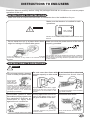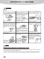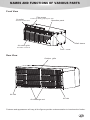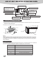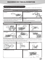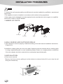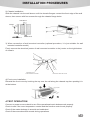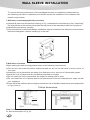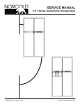
1
Foreword
F
O
R
E
w
O
R
D
*
C
O
N
T
E
N
T
S
This Instruction Manual is the standard version for all models for the packaged
terminal air conditioners manufactured by our company. The appearance of the
model that you purchased may be slightly different from the ones described in the
Manual, but it does not affect the proper operations and usage.
Please read this Manual carefully and keep the Manual available for reference at a
later time.
Addition to the user manual:
*The packaged terminal air conditioner is not intended for the use of young
children or infirm persons without supervision.
*The packaged terminal air conditioner shall be installed in accordance with
national wiring regulations.
*If the power cord is damaged,it must be replaced by qualified person in order to
avoid a hazard.
*Due to continual product improvement,the right is reserved to change specifications
and design without notice.
!
!
WARNING
This symbols refers to a hazard or unsafe practice which can result
in severe personal injury or death.
CAUTION
This symbols refers to a hazard or unsafe practice which can result
in personal injury or product or property damage.
Contents
Instructions to end-users
1
Names and functions of various parts
3
Use of unit mounted operation panel
4
Use of wall mounted controller
5
Use of hand held remote controller
6
Methods of maintenance
8
Diagnosis on troubleshooting
9
Installation procedures
10
Wall sleeve installation
12
INSTRUCTIONS TO END-USERS
Read this Manual carefully before using the packaged terminal air conditioner to ensure proper
operation of the unit.
INSTRUCTIONS TO INSTALLATION
* Make sure that an authorized technician or contractor does the installation for you.
Make sure that breaker is installed for safe
operations.
!
WARNING
S K
Earth Leakage
Circuit Breaker
If breaker is not installed, it may result in electric shock or other
hazards.
Do not install the unit in a place where there
might be leakage of inflammable gases.
Make sure that the power source of the unit is
properly grounded.
The grounding wire of the packaged terminal air conditioner
In the case that the gases are leaked out and accumulated must be firmly connected to the grounding wire of the power
around the machine, it may result in fire hazards or other source. Improper grounding will lead to possible electric shock
or other hazards.
accidents.
INSTRUCTIONS TO OPERATIONS
!
WARNING
Do not press, stretch, damage, Do not use the fuse with Do not insert sticks or other hard
heat or modify the power cord. improper capacity or other metal objections into the air inlet or
wires.
outlet.
Dangerous!
It may result in
electric shock,
overheating, fire
hazard or other
accidents. In the case that the power
cord is damaged or that a replacement
for the power cord is required due to
some other reasons, please contact our
company dealer or an authorized
maintenance technician.
Do not place such articles as
insecticides, paints or other
flammable spraying agents near
the packaged terminal air
conditioner or spray them
against the air conditioner.
Copper
wire
Improper use of metal wires ,copper
wires for the fuse may result in faulty
performances of the machine or fire
hazards.
If the air conditioner and the
burning appliances have to be
used in the same room, try to
get good ventilation in the room.
The high-speed rotation of the fan blades
may cause accidents.
Do not wash the air
conditioner with water.
NO!
Lack
of
oxygen!
NO!
It might result in fire hazards.
Insufficient ventilation may lead to the
hazard of anoxia.
It may cause electric shock or other
accidents.
1
INSTRUCTIONS TO END-USERS
!
CAUTION
Do not try to stop the operation
of the packaged terminal air
conditioner by pulling the power
cable from the socket.
Stop!
Make sure that there is no dust
on the plug before you plug in
the power socket and make
sure the plug is put correctly
plugged into the socket.
If there is dust on
the plug or the
plugg is not
properly done,
this could result
in electric shock,
This could result in electric shock, fire fire hazards or
other accidents.
hazard or other accidents.
Try to reduce the generation of Do not use the following
heat in the room during cooling articles:
operations. Place the heating
source outside of the room, if
possible,do not use burning
appliances in the air-conditioned
room.
Warm water (above 400C or 1040F)
Warm water might cause deformation or
fading of colors of the packaged terminal
air conditioner.
Gasoline, paint diluting agent, benzene and
abrasives, etc. may cause deformation or
It may lead to the incomplete burning of scratches to the packaged terminal air
conditioner.
these appliances.
Try as much as possible to
avoid the sunlight and warm
air from entering the room.
Scotching!
During the cooling operation, window
curtains or louver blinds are to be used
to shade off the sunlight.
Do not let the delivered air
blow to your body directly for
long time.
It might cause discomfort of your
body or harm your health.
Do not sit on the unit or place Check to see if the supporting
If the air conditioner is not to
heavy objects on it.
parts of the units are properly be used for a long period of
fixed and firm.
time, please pull out the plug
from the power source socket
to ensure safety.Turn off the
air conditioner
If the supporting
before pulling
parts are damaged,
out the plug.
repair them at once
The falling of
the unit might
cause body
injuries or other
accidents.
!
so as to prevent the
unit from falling
down which might
cause body injuries
or hurts.
WARNING
INSTRUCTIONS FOR REMOVAL AND REPAIRS
* If the unit needs to be removed for installation elsewhere or for repairs, please contact our
company dealer or authorized technicians.
* In case of occurrence of abnormality (burning smell, for example), please stop the operation
of the unit, disconnect the power and contact our company dealer or authorized techincians.
2
NAMES AND FUNCTIONS OF VARIOUS PARTS
Front View
Filter screen
Air outlet
To take out directly grasping from here
Operation panel
Air blows out from here.
Wall sleeve
Air return grids
For intake of room air
Front cover
Rear View
Outdoor grille
Air inlet
Air dircharge vent
Air inlet
Features and appearance will vary,all the figures provide a demonstration to introduce the funtion.
3
USE OF UNIT MOUNTED OPERATION PANEL
WARM button
Each pressing of this button will
raise the temperature setting by
1˚C or 1˚F.
Digital displayer
On normal operation it indicates room TEMP,
When pressing WARM or COOL button
it indicates setting TEMP; on timer operation
it indicates timer time; on failure operation
it indicates failure code.
WARM
+
COOL
-
COOL button
Each pressing of this button will
decrease the temperature
setting by 1˚C or 1˚F.
Operation mode indicator lamp
Fan speed indicator lamp
COOL
FAN
HEAT
LOW
MID
HIGH
POWER
MODE
MODE
Receiver of remote controller signal
FAN
ON/OFF
ON/OFF button
Press this button to turn the
machine ON or OFF.
Operation running indicator lamp
MODE button
Press this button to select the
operations among cool,fan,or heat.
FAN SPEED button
Press this button to select the fan
speed you want:low,mid,high.
Fresh air exchange procedure
1.Remove the front cover by pulling out at the bottom to release it,then lift it up to clear the rail
along the chassis top(Fig a).
2.Put the air exchange switch to open state(Fig b).
Front cover
fresh air
exchange switch
Fig a
Fig b
Note:
The air exchange switch is normally placed at the left closed position.When it is moved
to the right,the unit will discharge a little amount of air from inside room to keep the
air fresh,but if the switch is placed at the right position for long time,the cooling effect
will be affected.
Self Diagnosis Funtions
Our company has provided the thoughtful services for customers,and the air conditioner
had been installed self diagnosis system to display the code for failure.
Failure Code
4
Content of defect
E1
Communication failure
E2
Indoor coil temperature sensor failure
E3
Indoor temperature sensor failure
E4
System abnormality protection
E5
Outdoor coil temperature sensor failure
E8
Overheating protection/Defrosting
DF
Defrosting
USE OF WALL MOUNTED CONTROLLER
Wall mounted controller and hand held remote controller are optional parts,please read the
sections corresponding to the specific model you have choosen.
Room temperature indicator
Cooling indicator
Heating indicator
Fan speed indicator
Set temperature indicator
Fan indicator
ON/OFF button
Press this button to turn the
machine ON or OFF.
ON/OFF
FAN MID button
Press this button to set air flow rate
in middle speed.
FAN MID
FAN HIGH button
Press this button to set air flow rate
in high speed.
FAN HIGH
WARM
FAN LOW
COOL
FAN LOW button
Press this button to set air flow rate
in low speed.
MODE button
Press this button to select the
operations among cool,fan,or heat.
MODE
WARM button
Each pressing of this button will raise the
temperature setting by 1˚C or 1˚F,the
highest TEMP is 31 ˚C or 88˚F.
COOL button
Each pressing of this button will decrease
the temperature setting by 1˚C or
1˚F,the lowest TEMP is 16 ˚C or 61˚F.
Note:
1.Do not use nails or other sharp objects to press the button,because the sharp objects will scratch
the panel.
2.Pressing the WARM and COOL buttons together beyond 3 seconds can lock the panel
keyboard,and pressing the two buttons again would cancel the lock function.
3.When you turn on the machine,if the wall mounted controller is connected,there will be 4
seconds delay for operating the controller.In this time the unit mounted operation panel and hand
held remote controller will not work,but the digital pipe and indication lamp of operation panel
can work.If the wall mounted controller is disconnected,there will be 3.5 seconds delay for operating
the unit mounted operation panel and you will be able to operate the machine with hand held
remote controller.
Function of random time delay start-up
If it is in the situation of starting up before power cutting off, the PTAC will start up automatically
after the power is on. The LED will display it immediately following the memorial content, and
the relay will do the time delay start-up according to random numbers (120-240 seconds). This
function can prevent from the accident of electric network surge when the same type of airconditioners are installed in the same property and start up in the same time after power is supplied.
5
USE OF HAND HELD REMOTE CONTROLLER
TEMP indicator
indicates set temperature.
Operation mode indicator
Keyboard locked indicator
Fan speed indicator
Present time indicator
Timer time indicator
TEMP setting button
ON/OFF
This button is used to set the room
temperature.Each pressing of the "+"or
"-"button,the temperature setting is increased
or decreased by 1˚C or 1˚F.
ON/OFF button
Press this button to start or stop the units.
Operation Mode button
FAN SPEED button
Press this button to select the high
speed,mid-speed or low speed of air delivery.
This button is used to select the
cooling,fan or heating mode of operation.
FAN S
PEED
MODE
TIMER button
This button is used to set the switch-on or
switch-off mode .Used together with the "HOUR"
button,the time setting can be made within the
range of 1-12 hours,with the interval of one hour.
TIMER
HOLD
HOUR
MIN
HOLD button
Press this button to lock or unlock the
keyboard.
MIN button
This button is used to set the present time.
HOUR button
This button is used to set the present time
or the time for switch-on or switch-off.
Above figure shows all indications for the purpose of explanation,practically only the applicable
is indicated.
Cool/Fan/Heat mode operation procedure
* Press the ON/OFF button with the remote controller pointing toward the packaged terminal
air conditioner.
* Press the MODE button,select the operation mode:cool/fan/heat.
* Press + or - button, to set your desired temperature.The setting temperature range is 6188˚F(16-31˚C).
* Press the FAN SPEED button, to set your desired air flow rate:high/mid/ low.
6
USE OF HAND HELD REMOTE CONTROLLER
Present time setting procedure
When cells are inserted,the present time is automatically set to AM 0:00.EX.:set to AM10:30.
* Open the back cover,push the CLK button .The time indicator is flickering and can set the
present time.
CLK button
* Press the HOUR button.(set to AM 10:00)
This button set clock
* Press the MIN button.(set to 30)
RST button
* Press the CLK button again,and then close the back cover.
CLK
RST
This button let computer reset
Open the back Cover
Timer operation procedure
Timed switch-off
* During the operation ,press the TIMER button and the unit will enter the timed switch-off mode.
* Press the HOUR button to set the desired time,the timer can make the setting in the range
from 1-12 hours.
After the setting,the digits shown on the display screen will go down by 1 for every elapsed hour.
Timed switch-on
* In the standby mode,press the TIMER button and the unit will enter the timed switch-on mode.
* Pres the HOUR button to set the desired time,the timer can make the setting in the range
from 1-12 hours.
After the setting,the digits shown on the display screen will go down by 1 for every elapsed hour.
Releasing procedure
Press the TIMER button again to release the mode.
Replacement of batteries
When the signal from the remote controller becomes weak and the unit can not receive it properly,or
the indication on the display screen becomes blurred,please replace the hand held remote controller
with two new batteries.
Note:
1* The positive and negative poles must match the installation positions
2* Do not use an old battery together with a new battery.
3* If the hand held remote controller is not to be used for long time,take out the batteries so as
to prevent the leakage of the electrolyte from damaging the hand held remote controller.
7
METHODS OF MAINTENANCE
Before proceeding with the methods of maintenance, make sure that the packaged terminal air
conditioner is turned off and the plug is pulled out from the socket.
Before the operational seasons
1
2
3
Check to see if there are any blocking
objects around the air inlet and outlet of
the units.
During the operational seasons
Clean the air filter screen (at a standard interval of once
every two weeks).
1
Remove the air filter screen
Take out the air filer screen
directly grasping it from the
front cover
Check to see if the installation base is
corroded or rusty.
Check if the grounding is properly made.
ground wire
2
4
Check if the air filter screen is clean.
5
Connect to the power source
6
Load batteries in the remote controller.
(remote controller model)
If the air filter screen is very dirty, you may use
lukewarm water (about 300C or 860F) to clean it, and
then air it dry.
Note:
*
*
*
3
After the operational seasons
1 Set the temperature at
30 Cor 86 F and let the
machine run in cooling
mode for half a day.
Make the interior of the
unit dry.
0
2
0
Stop the operation of the
machine and turn off the power
switch.
Clean the air filter screen
4
Do not use boiling water to clean the screen.
Do not bake the screen dry.
Do not pull it with too much force.
Install the air filter screen.
If the air conditioner is operated without an air filter
screen, the interior of the unit will be contaminated
by dirt which might cause performance failure or even
damage of parts.
Clean the air conditioner
*
Use soft dry cloth to wipe
the air conditioner or use a
vacuum cleaner to do the
cleaning.
* If the air conditioner is very
dirty, you may use a piece of
cloth soaked with household
neutral detergent to do the
cleaning.
It is recommended to pull the plug from the
power socket in the non-operational season for
the sake of safety and saving energy.
the air filter screen and install it
3 Clean
back to place.
lean the air
4 Cconditioner.
5
8
Take the batteries out from the remote
controller (remote controller model).
Note:
If the air filter screen is blocked by dust, the
performance of cooling and heating
operations will be affected, the operational
noise will be larger and the power
consumption will be increased. Therefore,
periodic cleaning of the air filter screen is
necessary.
DIAGNOSIS ON TROUBLESHOOTING
Inspection and treatment prior to maintenance
Please check the following items before asking our company dealer or authorized technician for
after-sale services:
The packaged terminal air conditioner does not work at all.
Is the power plug inserted into the socket
properly?
Is there a power failure or
is the fuse blown?
No electricity!
Insert plug
Is the timer set for the "TIMER-ON" mode?
If the packaged terminal air conditioner (remote controller
model) is set for timed switch-on operation mode, it will not
start operating before the set time is reached.
Is the ambient temperature lower than 160C
or 610F ?
If so, the auto protection function of the air conditioner will
prevent the unit from cooling operation.
There is no sufficient cooling or heating.
Is the room temperature set
properly?
Is the air filter screen clean (not
blocked)?
Are the doors or windows
opened?
The air filter
is blocked
suitable
TEMP
close the
door
Is the room directly exposed
to sunlight?
Are there any heating sources Are there many people inside
the room?
inside the room?
Hot!
If the packaged terminal air conditioner remains abnormal in operation after the above checks and inspection, please disconnect
the power and contact our company dealer or authorized technician.
In any of the following cases, please turn off the power of the packaged terminal air conditioner
and immediately contact the dealer or authorized technician.
The fuse is frequently blown
or the breaker keeps shutting
off.
The electric wire turns
abnormally hot.
The insulation sheath of the
power cord is torn.
Fuse blown
frequently
The switches do not work.
There are abnormal noises when the machine
is operating.
9
INSTALLATION PROCEDURES
!
WARNING
To ensure the unit operates safely and efficiently,it must be installed by qualified or experienced
technicians.
*The appliance must be installed in accordance with national wiring regulations.
*If the supply cord is damaged,it must be replaced by the manufacturer service agent or a qualified
technician in order to avoid a hazard.
1.NAMES OF PARTS
outdoor grille
wall sleeve
chassis
front cover
2.WALL SLEEVE AND OUTDOOR GRILLE
1)The wall sleeve must be properly installed accoding to the wall sleeve installation instructions
(Page12-15).
2)Install the outdoor grille from the room side.If replacing and old chassis with an existing grille
or using a specialized grille in a new installation,please contact our company dealer to determine
if the new chassis should be used with the nonstandard specialized grille.
3.INSTALLATIOIN
1)Front cover removal
Remove the front cover by pulling out at the bottom to release it,then lift it up to clear the rail
along the chassis top.
Front cover
10
INSTALLATION PROCEDURES
2) Chassis installation
Slide the chassis into the wall sleeve until the chassis flanges contact the front edge of the wall
sleeve, then secure with four screws through the chassis flange holes.
Wall Sleeve
Chassis
Outside Wall
Slide Chassis In
3) Wires connection of wall mounted controller (optional procedure, it is just suitable for wall
mounted controller model)
Firmly connect the electrical junctor of wall mounted controller to the junctor on the right bottom
of chassis.
Electrical junctor
of wall mounted controller
Press down here with thumb
4) Front cover installation
Reinstall the front cover by hooking the top over the rail along the chassis top,then pushing it in
at the bottom.
Front cover
4.TEST OPERATION
Connect to power source,check to see if the operational mode buttons work properly.
Check to see if the room temperature control and the function control work properly.
Check if the water drainage is smooth and unblocked.
Check if there are abnormal sounds during operations.
11
WALL SLEEVE INSTALLATION
To ensure the best performance of the packaged terminal air conditioner,please observe
the following wall sleeve installation procedures and do the installation in accordance with
related requirements.
1.Wall sleeve assembly(optional procedure)
a)Unpack all parts and accessories,referring to Fig 1,assemble the wall sleeve by first ”cliplocking”
the side pieces to the bottom piece,then the top piece to the assembled side and top pieces.
b)Handle the wall sleeve carefully.
c)If the wall sleeve is deformed,chassis installation may be hindered.If the wall sleeve has become
deformed,straighten it before installing it in the wall.
CLIPLOCK
SLEEVE
PIECE
OM
TT
BO
Fig 1
2.Wall sleeve location
When making the wall opening,please observe the following requirements:
a)The air inlet and outlet should be unblocked and the air can be delivered to every corner of
the room.
b)Install the unit in places that are away from heat sources or sources of inflammable gases.
c)Install the unit in places that are not directly exposed to sunlight.
d)Do not install the unit in places that are subject to strong wind or dust.
e)Do not install the unit in places where the operational noise and exhausted air might trouble
your neighbors.
f)There should be sufficient space margins around the unit to facilitate maintenance and repairs(refer
to Figs 2 and 3)
Critical dimensions:
3"MIN
(D1)
CEILING
WALL CASE
OUTSIDE
SEE NOTE
(D2)
INSIDE ROOM
2"MIN
(D5)
1/4" MIN
(D3)
2"MIN
(D5)
SEE NOTE
(D4)
FINISHED FLOOR
OR TOP OF CARPET
Fig 2
Fig 3
Note:Care should be taken in location of electrical supply entry in relationship to the sleeve
for later access(refer to Fig 10).
12
WALL SLEEVE INSTALLATION
Chart 1
Dimensions
Recommended installation clearance
D1
Top of case to finished ceiling-3”min
Projection of case into room-1/2”minimum up to 13/4”maximum without use of electrical sub-base.
Note: 2-3/8”minmum when sub-base is used.
D2
Minimum projection of case to the outside-1/4”.
D3
D4
Height above finished floor or top of carpet-1/2”minimum,
2”recommended without sub-base-3”minimum with subbase
D5
Left/right side of case to adjacent wall-2”min.
3.Preparation of the wall
The sleeve should be installed during construction and lintels should be used to support the block above
the wall sleeve.The sleeve can not support the load of bricks/blocks.
For existing construction,wall opening must be created,the proper dimensions are necessary to avoid
use of fillers or additional framing.The sleeve is modular in height and width(refer to Fig 4& Chart 2).
Height:
Fits 2 courses concrete block
Fits 6 courses standard brick
Fits 5 courses jumbo brick
Width:
Fits approximately 3 stud spaces.
MAIN STUD
HEADER-4"X4"OR
2-2"X4"ON EDGE
JACK STUDS
ADJUST FRAMING
16-1/4" MIN.
TO SECURE THIS
42-1/4" MIN.
JACK STUD
DIMENSION
FINISHED FLOOR
CRIPPLE
SUB-FLOOR
( See Chart 1)
Fig 4
Chart 2
using field supplied sleeve angles
not using field supplied sleeve angles
minium finished
opening dimensions
height
width
16-1/4"
16-1/4"
42-1/2"
42-1/4"
sleeve dimensions
height width
16"
42"
depth
13-3/4"
(16"/18"/24")
Note:1"equals to 25.4mm,please refer to using.
13
WALL SLEEVE INSTALLATION
If the field supplied case angles must be used during installation(Fig 5),proceed as follows:
a)Position the case angles around top and sides of sleeve to get the proper depth,(be sure to
have the angles pointing outside).
b)Mark the sleeve using the case angles as a template for screws.
c)Drill Ø5/32”hole at the marked position,(from step 2 above)only use 10X1/2”screws.
d)Install the screws from the outside of the sleeve,do not drill any holes in the base of the sleeve.
Fig 5
4.Installation of the sleeve in the wall opening
a)Place sleeve into the wall,refer to Chart 1-D2 for room side projection(minimum 1/2”to a maximum
1-3/4”without subbase).The rear(outside)edge of the sleeve should stick out a min.of 1/4”past the
outside wall to be able to caulk properly,do not seal the drain holes on the outside(grille side)of
sleeve.If it is desired to have the rear grille flush on the outside,a drip rail must be installed under
the sleeve and caulking applied between the drip rail and sleeve.
b)To ensure the unit’s maximum efficiency,the sleeve must be installed a slight downward pitch
from the indoor side to the outdoor side(Fig 6),then fasten the wall sleeve(Fig 7)
c) Lintels should be used to support the block above the wall sleeve(Fig 8).The sleeve can not
support the load of bricks/blocks(if directly under a window sill,use of lintel may not be necessary).
Inside
Outside
Level
1/4 Bubble
Wall Sleeve Tilt To Outside
Molly or toggle bolt
Wood screw
Expansion anchor bolt
Fig 6
Outside Wall
Fig 7
Corrugated plate Inside wall
Fig 8
Note:The fastening parts and wood screws etc. are prepared by end-users themselves.
14
WALL SLEEVE INSTALLATION
5.Weather proofing:
Weather proofing gaps between the exterior wall and the sleeve with caulking or other equivalent
weather proofing material(Fig 9)
Fig 9
Note:installation in extra thick walls:
a) If the sleeve is being installed in a thick wall where the sleeve is recessed more than 3”, an
extended wall sleeve will be required with depths as called out in chart 1 .
b)If the sleeve is being installed in a wall where the recess 3” or less, a flashing must be installed
under the sleeve and extend up 2” on each side. The flashing must include a drip rail as shown
above Fig 9.
6.Electrical requirements
Provisions should be made to have a proper electrical outlet near the sleeve. All wiring must
be made in accordance with local codes and regulations. The line cord included with the chassis
(if used) will extend to a wall receptacle located with in the area shown in Fig 10 .
Fig 10
MODEL
"A"
21"
"B"
58"
WALL RECEPTACLES
15