1
Digital Microsystems
UJJ '"
DM5-S000 PROGRAMMER'S MANUAL
Version 1.0
Copyright
©
1983, Digital Microsystems
COPYRIGHT
All rights reserved. No part of this manual may be reproduced
without the prior written permission of Digital Microsystems,
Inc.
Digital Microsystems
",17S5 Embarcadero, Oakland, CA 94606
(415)532-3686 TWX 910-366-7310
NOTICE
Digital Microsystems, Inc. reserves the right to make improvements to the products described in this manual at any time,
without notice.
TRADEMARKS
HiNet, DMS-5000, DMS-5080, DMS-5086, DMS-3F, amd DMS15, are trademarks of Digital Microsystems, Inc. CP/M, and
CP/M86, are trademarks of Digital Research, Inc. MX-l00 is a
trademark of fpson, Inc: Microline-83A is a trademark of
Okidata, Inc.
Manual written by:
Robert Weber and Alan H. Stacy
Design & Illustration by:
Deborah Russell
@
Copyright 1983, Digital Microsystems, Inc.
TABLE OF ,CONTENTS
CHAPTER
PAGE
1.0 The DMS-5000 System Description ............
2.0 Modes of Operation ........................
2.1 Half Duplex Mode .......................
2.2 Monitor Mode ..........................
2.3 Character Display on the 5000 Console .....
1-1
2-1
2-1
2-1
2-2
2-4
2-5
2-5
2-6
2-7
2-8
2-10
2-11
2-16
2-18
2-18
2-21
2-25
2-25
2-27
2-28
2-28
2-31
2-32
2-33
2-35
3-1
3-4
3-5
2.3.1 Vert Mode Display in Horiz Orient..........
23.2 Clearing the Screen ..................... "
2.3.3 Positioning the Cursor. . . . . . . . . . . . . . . .. . . ..
2.3.4 Character Enhancements. . . . . . . . • . . . . . . . . ..
2.3.5 Cursor Display Controls ...................
2.3.6 Scrolling Control. . . . . . . . . ... . . . . . . . . . . . . ..
2.3.7 Alternate Character Sets ...................
2.3.8 Character Set Formats . . . . . . . . . . . . . . . . . . . ..
2.3.9 Character Positioning. . . . . . . . . . . . . . . . . . . . ..
2.3.10 Descender Tables. . . . . . . . . . .. . . . . . . . . . . . ..
2.3.11 Transposition Tables. . . . .. . . . . . . . . . . . . . . . ..
2.4 Graphic Line-Drawing Mode ..............
2.4.1 Shape Display & Screen Orient ........... "
2.4.2 Status Enquiry ............................
2.4.3 Screen Write Modes ......................
2.5 Point Plot Mode .........................
2.6 Graphic-Input Mode .......................
2.6.1 Bit Map Block Screen Fill ..................
2.6.2 Shape Display & Screen Orientation. .. .. . . ..
2.6.3 Bit Mapped Shape Memorization. . . . . . . . . ..
2.6.4 Printing Graphics .........................
3.0 Programmable Function Keys. . . . . . . . . . . . . . ..
3.1 Function Key Number ................... :
3.1.1
Function Key Number Report. . . . . . . . . . . . ..
4.0 DMS-5000 Series CRT Control Codes Summary .
4.1 Screen Brightness Control .. . . . . . . . . . . . . . ..
4.2 Character Enhancement Control ...........
4.3 Horiz Mode Character Size Selection. . . . . ..
4.4 Cursor Display Controls. . . . . . . . . . . . . . . . . ..
4.5 Scrolling Control . . . . . . . . . . . . . . . . . . . . . . . ..
4.6 Graphic Screen Write Modes . . . . . . . . . . . . ..
4.7 Bit Map Block Screen Fill . . . . . . . . . . . . . . . . ..
4.8 Bit Mapped Shape Memorization ..........
4.9 Cursor Positioning Control ................
4.10 Alternate Character Sets ...................
4.11 Graphic Line Drawing Mode ...............
4.12 Graphic-Input Mode ......................
4.13 Parallel Printer Port Access ................
4.14 DMS-SOOO Test Functions ..................
4.15 Local Functions ..........................
5.0 Escape and Control Codes Index. . . . . . . . . . . ..
Appendix .....................................
Index .........................................
4-1
4-1
4-1
4-2
4-2
4-3
4-3
4-4
4-4
4-5
4-6
4-6
4-7
4-7
4-8
4-8
5-1
A-1
1-1
LIST OF DIAGRAMS
2-1
2-2
2-3
2-4
3-1
3-2
ii
Character positioning ......................
Report format for graphic line drawing mode
Shape fill and screen orientation ...........
Report format for graphic input mode ......
DMS-SOOO keyboard layout &
programmable keys .......................
Byte structure for function keys ............
2-20
2-23
2-26
2-30
3-3
3-6
DMS-5000 Programmer's Manual
1.0 THE DMS-SOOO SYSTEM DESCRIPTION
The DMS-5000 series are general function
microcomputer workstations for use with the
HiNet local area network. There are two CPUs
available in the series. The 5080 has an 8-bit
CPU operating under CP/M-80 and the 5086 has a
16-bit CPU using CP/M-86. The unit contains a
microcomputer with serial and parallel connections for I/O and network mass storage, a highresolution bit mapped CRT display with intelligent controller and a detachable keyboard. The
host computer and CRT controller are two
separate PC boards within the 5000 package that
are connected by a handshaking parallel communications port. The CRT and keyboard act as a
user console to the host computer.
A DMS-5000 Workstation may be viewed by the
programmer as a computer with a separate
graphics CRT terminal. This manual is primarily
concerned with the use of the CRT console and
its features. For programming information on the
host computer, consult the HiNet User Manual.
The DMS-5000 CRT, CRT controller and CPU
boards are housed in a specially designed case
that may be detached from its base and mounted
with the CRT screen in either a vertical or a
horizontal orientation. A mercury switch on the
CRT controller senses the orientation in use and
adjusts the character display accordingly.
release: 5/1/83
1-1
DMS-5000 Programmer's Manual
The CRT uses a P-39, long-persistence
phosphor for flicker-free operation. After about
15 minutes of inactivity, a timeout feature will
dim the screen intensity down to a level that
protects the phosphor from burnout. Touching any
key--except Shift, Shift Lock or CTRL--or
receiving any code from the host computer will
bring the screen intensity back to its original
level.
The CRT display is capable of character and
fully bit-mapped graphics display plus:
•
•
•
•
•
•
•
Variable character sets
Inverse and underlined characters
European character sets
Line drawing
Point plotting
Bit-mapped block area fill
Bit-mapped shape memorization
These various features are accessed by using
ASCII Control and Escape character sequences
embedded in the console output stream.
The console keyboard has a standard
typewriter layout with a separate numeric/cursor
-control keypad and a row of sixteen programmable function keys. Except for the ENTER key,
all of the keys in the numeric keypad plus the
three blank keys in the main keyboard are also
programmable. See Diagram 3-1 for an illustration of the keyboard with all of the function
keys numbered.
release: 5/1/83
1-2
DMS-5000 Programner I s
~1anual
2.0 MODES OF OPERATION
There are four modes for graphics display
in the 5000: Character Display, Line Drawing
Mode, Point Plotting Mode and Graphic Input
Mode. The 5000 can also be set to function in
Half Duplex Mode and has a convenient Monitor
Mode for debugging.
2.1 HALF DUPLEX MODE
Half Duplex Mode enables the 5000 to send
characters to both the CRT screen and to the
host CPU or to a modem through either serial
port 0 or serial port 3. (The serial port used
by communications packages is specified by the
program.) This is useful in running communications packages when the 5000 is interfacing with
a distant computer over a phone line.
The Half Duplex and Full Duplex Modes are
selected with the Local Function keys. To enter
Half Duplex Mode, hold down the Shift and
Control keys while striking Fl1. To return to
Full Duplex Mode, depress F12 while holding down
both the Shift and Control keys.
CTRL/SHIFT Fll -- Half Duplex Mode
CTRL/SHIFT F12 -- Full Duplex Mode
2.2 MONITOR MODE
The DMS-5000 can be put into Monitor Mode
by sending an ESC Q (lBH,51H) or by pressing
release: 5/1/83
2-1
DMS-5000 Programmer's Manual
CTRL/SHIFT F4. Once in Monitor Mode, ESC or CTRL
sequences will not be processed by the CRT
controller but will instead be displayed on the
screen as abbreviated codes. This allows the
programmer to see a program on the CRT and check
for errors. The abbreviations for the codes are
listed in Appendix B. To exit Monitor Mode and
return to Full Duplex Mode, send ESC q (1 BH, 71 H)
or press CTRL/SHIFT F7.
ESC Q (lBH,51H)
Enter Monitor Mode
ESC q (lBH,71H)
Exit Monitor Mode
CTRL/SHIFTF4
Enter Monitor Mode from
keyboard.
CTRL/SHIFT F7
Exit Monitor Mode from
keyboard.
2.3 CHARACTER DISPLAY ON THE 5000 CONSOLE
Upon initialization (power-up or reset
condition) the console is set to Character
Display Hode. This mode operates in the same way
as standard CRT terminals. The alpha cursor,
seen as a flashing rectangular block, resides at
the current display position. Characters are
displayed sequentially as input, left to right,
from the starting cursor position. When the
cursor comes to the end of a line, it moves to
the beginning of the next line. At the end of
the screen, the display scrolls up one line, the
. top line is discarded and display continues. The
maximum length and number of lines that can be
release: 5/1/83
2-2
OMS-SOOO Programmer's Manual
displayed at one time depends upon the orientation of the CRT and/or the character size
selected.
CHARACTER SIZES
In the vertical orientation the characters
are displayed in an 80-column by 66-line format,
utilizing a 5x7-bit character mapped into a
7x12-bit character cell. The 5x7 character can
be dropped 2 pixels to provide for a descender.
In the horizontal orientation, two
character sizes and three "page" lengths are
available, giving three screen formats:
An 80 column by 24- OR 26-line format using
a large 8x13 bit character-(4 bit descender) in
a 1Ox21-bi t cell.
A 132-column by 50-line format using a
small 5x7-bit character (2-bit descender) in a
6xl1-bi t cell.
In the horizontal orientation, selection
between character formats is accomplished with
the following escape codes:
ESC H (lBH,48H)
Set 80-col. x 24-line format.
ESC S (lBH,53H)
Set 132-col. x 50-line format.
When either of these codes are called, the
scroll counters are reset and the proper size-alpha cursor will appear in the upper left-hand
corner of the display. The screen is not
release: 5/1/83
2-3
DMS-5000 Programmer's Manual
cleared, therefore characters of both sizes can
appear on the screen simultaneously.
In horizontal mode the 5000 can be set to
display either the default 24 lines or 26 lines
of text without resetting the scroll counters
when the format is changed.
E&: ;
(lBH,3BH)
BO-col. x 26-line format.
E&: :
(l BH, 3AH)
80-col. x 24-line format.
If you want both character sizes to be
displayed at the same time, the screen must not
have been scrolled since the last characters
were written or interlace inversion--even and
odd scan lines are interchanged--will occur. If
you do not want both fonts to be displayed, you
should still clear the screen (CTRL L) before or
after changing formats, just to be safe.
2.3.1 VERT. MODE DISPLAY IN UORIZ. ORIENTATION
If the 5000 is operating in horizontal
mode, sending an ESC v will change the display
mode and characters to the vertical orientation
even though the CRT remains physically
horizontal. To return to horizontal mode, send
either ESC H for 80-col. x 24-line format or ESC
S for 132-col. x 50-line format. Remember that
ESC H and ESC S will reset the scroll counters.
ESC v
(1 BH, 76H)
release: 5/1/83
vertical characters in
horizontal orientation.
2-4
DMS-5000 Programmer's Manual
2.3.2 CLEARING THE SCREEN
There are three codes that can also be used
for clearing the screen. CTRL L (OCH) will clear
the entire screen and home the cursor. ESC K
(lBH,4BH) will clear all characters after the
cursor position to the end of the current line.
ESC k (lBH,6BH) will clear all characters after
the cursor position to the end of the screen.
CTRL L (OCH)
Clear entire screen, horne cursor.
FS: K
(lBH,4BH) Clear to end of line.
FS: k
(lBH,6BH) Clear to end of screen.
2.3.3 POSITIONING THE CURSOR
The alpha mode cursor may be posi tioned on
the screen by the following commands:
CTRL A (OlH)
Homes cursor to upper left
posi tion of screen.
CTRL L (OCH)
Clears screen and homes cursor.
BACKSP1\CE
Moves cursor one column to
the left.
(CTRL H)
(08H)
CTRL F (06H)
Moves cursor one column to
the right.
LINEFEW (OAB)
CTRL J
Moves cursor one line down.
release: 5/1/83
2-5
DMS-5000 Programmer's Manual
C'.l'RL Z ( 1AH)
Moves cursor one line up.
<CR> (ODH)
Moves cursor to beginning of
current line.
(C'l'RL M)
J!SC
Y (lBH,59H) [row+2Oh,col+20h]
Sets absolute cursor position.
Cursor position starts fran col
~
row
.2.!..
To calculate the absolute cursor position:
row number (hex) + 20 hex = x coordinate
column number (hex) + 20 hex = y coordinate.
Example: to set cursor to row 4, column 12:
row 4 = 04H
column 12 = OCH
ESC·Y (20+04=24) (20+OC=2C)
or
1B 59 24 2C Hex
The cursor may also be positioned on pixel
boundaries instead of row and column intersections. See section 2.4, Graphic Line Drawing
Mode.
2.3.4 CHARACTER ENHANCEMENTS
The available character attributes are
underline and inverse video. These are set with
the following codes:
J!SC R
(lBH,52H)
release: 5/1/83
Turns on inverse video for all
succeeding characters.
2-6
DMS-5000 Programmer's Manual
N.,
ISL\\U\<.
NoH {\ L to - 15 R \ G.. i~ "\
ESC U
(lBH,55H)
ES:! 0
(1BH,4FH)
m:
N
(lBH,4EH)
ESC T
(1BH,54H)
Turns on underline mode for all
succeeding characters.
Turns on character overstrike
mode. Allows characters to be written
over by another character.
Returns all succeeding characters
to normal. (Turns off ESC R, ESC U
and ESC 0.)
Toggles whole screen inverse video
on/off.
2.3.5 CURSOR DISPLAY CONTROLS
Upon power up, the character-mode cursor
(alpha cursor) appears as a flashing block the
size of a character cell. (The vertical-mode
cursor is about 3/4 the size of a character
cell.) The cursor can be set not to flash or it
can be turned off altogether.
The cursor display codes are:
ESC D (lBH,44H)
Makes the cursor invisible.
ESC E (1 BH,45H)
Makes the cursor visible
again.
ESC f
(lBH,66H)
ESC F (1BH,46H)
Non-flashing cursor.
Flashing cursor.
When Local mode is entered, the cursor
changes from a flashing block to a non-flashing
release: 5/1/83
2-7
DMS-SOOO Programmer's Manual
block. The cursor will return to flashing made
when Local made is exited. If the cursor is
moved fast enough, it will time out and become
invisible until it stops for 0.5 seconds.
See page 2-21, section 2.4, for important
information on cursor positioning when exiting
Graphic Line Drawing Made.
2.3.6 SCROLLING CONTROL
AN IMPORTANT NOTE ABOUT SCROLLING
To increase efficiency and speed of
scrolling on the bit-mapped display, hardware
scrolling counters have been incorporated into
the CRT controller design. These counters point
to the address in the screen memory where the
screen scan will begin. Thus, to scroll the
scr~n one line up, the counters are loaded with
the address of the beginning of the next
character line from the top. When the screen is
cleared, or the character format is changed, the
scroll counters are reset to the original
positions.
The DMS-SOOO CRT uses an interlaced-field
display scheme. The scanning beam must make two
complete passes to refresh the screen entirely.
The first pass scans the even lines and the
second pass scans the add lines. Television
works in much the same way.
The combination of hardware scrolling with
interlaced raster scan may cause problems for
the unwary programmer. For instance, if the
release: 5/1/83
2-8
DMS-5000 Programmer's Manual
'>. <:~ .........__ -
......,.,.,..""",
_~'~<L..:;t
scrolling counters are reset after the screen
has been scrolled, the characters that have been
written after scrolling will jump to the top of
the screen, and their scan lines will be inverted, giving the text a very jumbled appearance •
.-
~lJl
31.
5L:~.- "-'>-
''-''-..
~~-~c)\"....·....-
0\> \...~.,....._:tJi ~JQ
Another possible problem can occur because
all graphics functions assume that the screen
has not been scrolled since entering graphics
mode. Any graphics display written to a scrolled
screen will appear to be wrapped around the
screen.
These problems can be completely avoided by
following these rules:
1. Clearing the screen (CTRL L (OCH» will
reset the scroll counters. Always clear the
screen before using any graphics functions.
2. Changing between large-character (80 x
24) mode and small-character (132 x 50) mode
will reset the counters. Clear the screen when
changing formats. If you want both character
sizes to appear on the screen, don't clear the
screen between fonts, but make sure that the
screen is not scrolled before changing. (Do not
write beyond the line limit of the format you
are using.)
.
3. To avoid these problems while creating
complex displays using graphics and mixed text
fonts, you must first clear the screen (CTRL L
(OCH», and turn the scrolling off (ESC (
(lBH,28H» before putting anything on the
screen. Be sure to turn the scrolling back on
release: 5/1/83
2-9
DMS-5000 Programmer's Manual
(ESC) (l BH,29H» before the end of your
application.
Scrolling may be disabled when it is
necessary to combine graphics and text or, when
in the horizontal orientation, two different
character sizes must show up on the same screen.
Whenever complex displays_ using both text pnd
graphics are to be drawn, it is advisE.pl~LJ:O
·clear the _~creen -first a~ d~ grollj.ng.
~ill guard against interlace inversion and
graphics wrap-around.
Scrolling commands:
2.3.7 ALTERNATE CHARACTER SETS
Various character sets are implemented in
the DMS-5000 Series. Several sets of standard
European characters are included in the
character generator. To access these sets send:
~
L (l BH,4CH) [Character set code]
release: 5/1/83
2-10
DMS-5000 Programmer's Manual
Character set codes:
= ASCII
= BRITISH
o = DANISH
F = FRENCH
G = GERMAN
= DU'ICH
A
H
B
I =
(HOLLAND)
ITALIAN
N = NORWEGIAN
S = SWEDISH
2.3.8 CHARACTER SET FORMATS
An entirely new character set, whether
supplied with the 5000 by DMS or designed by the
user, may be loaded into the CRT controller from
the host computer. An Escape code is sent,
followed by a two-byte count for the absolute
length of the set, and then the bit maps for the
96 printing characters in ASCII beginning with
20H. See the Data Structures for ASCII characters
in Appendix (A) for the actual format of a
down-loadable character set.
The code for loading a character set is:
:ROC
c (1 BH, 63H) [Download character set]
[download: least significant bit to most
significant bit]
The length and format of a character set
depend upon the current display orientation and
the selected character size. Each set consists
of 96 characters, with a given number of bytes
in its bit map. The character sets can be categorized into three types: horizontal large
format, horizontal small format and vertical
format.
release: 5/1/83
2-11
DMS-5000 Programmer's Manual
HORIZONTAL LARGE FORMAT CHARACTERS
The horizontal large-format character set
is a block of 1344 (decimal) bytes. Each character set is broken down into 96 characters that
are each 14 bytes in length. The characters are
written from these bit maps from the top down.
The far left pixel in each scan line is the most
significant bit in the byte. A capital "A" would
look like this:
PIXEL PATTERN
HEX CODE
OOH
18H
24H
42H
42H
42H
42H
7EH
42H
42H
42H
42H
42H
E7H
A line in assembly code for this character
would look like this:
DB
OOH,18H,24H,42H,42H,42H,7EH,42H,42H,42H,42H,42H,1
iA
To assemble a character set that can be
downloaded from the host, 96 of these lines
release: 5/1/83
2-12
DMS-5000 Programmer's Manual
would be written for the printing codes in the
ASCII sequence, beginning with the SPACE
character, 20H. (This character is usually
filled with all zeros.)
A four-byte header, including the ESC code
and the character set length in bytes, is placed
in the beginning of the file to let the CRT
controller know that a character set is to be
loaded.
DB
1BH,63H
DW
1344
ESC c - LOAD CHAR. SET
CHAR. SET LENGTH.
This file is assembled and made into a
binary image file. When this binary image is
transmitted to the console, the character set is
loaded into the controller's memory. From that
point on it is used until: a new character set
is loaded, the screen format is changed, or the
work station is reset.
HORIZONTAL SMALL-FORMAT CHARACTERS
The horizontal small-format character set
is a block of 768 (decimal) bytes. It is broken
down into 96 characters, each 8 bytes in length.
The characters are written from these bit maps
from the top down, again with the most significant bit representing the far left pixel in each
scan line.
release: 5/1/83
2-13
DMS-5000 Programmer's Manual
A lower case ''b'' would look like this:
PIXEL PATTERN
HEX CODE
OOH
40H
40H
58H
64H
44H
64H
58H
NOTE---The upper row of pixels and the
right-most two columns of pixels must ALWAYS
remain blank, or the characters will run into
each other. This is actually a 5X7 matrix.
The assembly code line for this character would
be:
DB
OOH,40H,40H,58H,64H,44H,64H,58H
A character set load file may be created in
the same way as a large-format file as shown
before except that the length count will be
different.
DB
OW
1BH,63H
768
release: 5/1/83
; ESC c - LOAD CHAR. SET
CHAR. SET LENGTH.
2-14
DMS-5000 Programmer's Manual
VERTICAL-FORMAT CHARACTERS
The vertical-format character set is a
block of 576 (decimal) bytes. It is broken down
into 96 characters, each 6 bytes in length. The
characters are written from these bit maps from
LEFT TO RIGHT, with the most significant bit in
each byte representing the top pixel in each
scan line. Thus, a lower case ''btl would look
like this:
PIXEL PATTERN
07011 0
oF
All E
HEX CODES
HHHHHH
The code line for this is:
DB
OOH, 7FH,OAH, 11 H, 11 H, OEH
Note the difference in coding scheme from
the horizontal characters. Since the screen is
turned 90 degrees, the scan lines are now
running up and down, rather than left to right.
The coding for the characters must be compatible
with this.
release: 5/1/83
2-15
DMS-5000 Programmer's Manual
The header for this file would be:
DB
OW
1BH,63H
576
ESC c - LOAD CHAR. SET
; CHAR. SET LENGTH.
See Appendix A for examples of these
structures.
2.3.9 CHARACTER POSITIONING ON THE SCREEN
HORIZONTAL MODE
The first character displayed on the screen
after a clear screen command is set flush with
the left- hand side of the screen, 6 pixels down
from the top. This places the UPPER RIGHT hand
corner of the first character at coordinate
0,553 (x,y). This positioning is consistent with
either small or large character sets. To find
the pixel position of any alpha mode character
cell, use the following conversions.
FOR LARGE CHARACTERS:
All values start at O.
Cell is 10 pixels wide by 21 pixels high.
x = col x 10
y = 553 -
(row x 21)
FOR SMALL CHARACTERS:
Cell is 6 pixels wide by 11 pixels high.
x = col x 6
release: 5/1/83
y
= 553
-
(row x 11)
2-16
DMS-5000 Programmer's Manual
In these equations (x,y) are the screen
coordinates of the upper-left hand pixel of the
character cell, and (row,col) are the alpha mode
character positions.
NOTE---These coordinate values represent
the upper left-hand pixel of the cell. They do
NOT directly correspond to the origin of a
character positioned using graphics mode in the
Tektronics 4010 emulation. When you position a
character at a non-standard coordinate by
entering graphics mode, issuing a coordinate,
and reentering character mode, the coordinate
issued points to the pixel 12 points down from
the top of the character cell, on the left hand
side. This point approximates the LOWER LEFTHAND SIDE of the character cell (a little higher
for the large characters, a little lower for the
small characters), the same way a 4010 does.
Thus, if your goal is to pixel-position characters relative to alpha-position character cells,
the above formulas apply, except that the y
origin is equal to 541. (553-12)
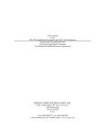
Diagram 2-1. Shows characters and sample
positioning coordinates in horizontal and
vertical display mode.
VERTICAL ORIENTATION
In the vertical orientation, the first
character cell (the character in the upper left
hand corner of the screen) is set flush with the
top left of the screen. The same rules that
govern character positioning in horizontal mode
apply in vertical mode.
release: 5/1/83
2-17
OMS-SOOO Programmer's Manual
This formula calculates the pixel position
for the alpha character cell in vertical mode:
x
= col x 7
y
= 799
- (row x 12)
All values start at zero.
Cell is 7 pixels wide by 12 pixels high.
2.3.10 DESCENDER TABLES
If a new character set is loaded into the
CRT controller a ~ table should
accompany it. A descender table is a string of
96 bytes with each byte representing a character
of the character set. If a byte is set to 0, the
character will be displayed on the base line. If
the byte is set to anything but 0, such as 1 or
ff, the character will be dropped down two or
four pixels so that part of it will be below the
base line. An "e" would have a 0 descender byte
and a "p" or "q" would have a 1 descender byte.
The code for loading a descender table is
ESC I (lBH,27H), followed by the 96-byte
sequence. If a new character set has descending
characters in the same position as the default
ASCII set, then it is not necessary to create
and load a new table.
2.3.11 TRANSPOSITION TABLES
In some applications using custom character
sets, it is desirable to change the codes coming
from the keyboard to accommodate different
keyboard layouts. For this purpose, a loadable
release:S/1/83
2-18
DMS-5000
Programmer's Manual
transposition feature has been implemented. A
table, stored in RAM, is used to translate each
code corning from the keyboard into an alternate
code. For a normal ASCII keyboard, a default
table would be the binary numbers 0 through 127,
in effect transposing each code for itself. This
default table is pre-initialized on startup and
when the 5000 is reset or sent an ESC x.
An ESC w will prompt the host CPU to load a
128-byte transposition table into RAM. If, for
example, the upper-case characters "A" and "Q"
were to be transposed, the 66th byte would
become 81 (decimal), and the 82nd byte would
become 65. Since the transposition table is only
128 bytes long, the numeric keypad cannot be
changed with this feature.
EOC w (lBH,77H)
[128 byte sequence]
Load keyboard transposition
table.
ESC
x (1 BH, 78H)
release: 5/1/83
Reset transposition table
to default values.
2-19
DMS-5000 Programmer's Manual
(49,53)
(40,53)
(45,51)
(40,51)
..
baseline
descender
(40,40)
underline
baseline
(40,40)
descenderline
underline (6 pixel,
below 'baseline)'
Large character
10 x 21 cell size
8 x 13 character
4 pixel descender
1 I"
(40,51)
(40,40)
Small character_
6 x 11 cell size 5 x 7 character
2 pixel descender
=
11
(46,51)
baseline
descenderunderline-
Vertical Mode Character
7 x 12 cell
5 x 7 character
2 pixel descender
tline drawn
-from (0,0)
Diagram 2-1. Character positioning and sample
coordinates. Note use of graphic line drawing mode
to position characters. (See Section 2.4)
release: 5/1/83
2-20
DMS-5000 Programmer's Manual
2.4 GRAPHIC LINE-DRAWING MODE
Upon receipt of the cooe CTRL ] (l DH) the
5000 will enter graphic line-drawing mooe. This
mode is a direct emulation of the line-drawing
mooe in the Tektronix 4010 graphics terminal.
The screen coordinates are transmitted as a
sequence of four bytes. The first pair of bytes
defines the Y position and the second pair the X
position. Within each byte, the lower-order 5
bits determine the coordinate value and the
upper 2 bits are tag bits that mark which part
of the coordinate--high or low--the byte is. A
maximum of ten bits are available to be used as
coordinate values.
NOTE---The absolute positions of X and Y
screen coordinates are dependent upon the CRT's
orientation. A pixel coordinate given for a
horizontal screen will point to a different
location on the screen in vertical mooe. For
example, the approximate center position on a
horizontal screen is pixel 390,280. This would
be a point that is 110 pixels down and 110
pixels to the right of the center (280,390) of
the screen in vertical orientation. (Refer to
Diagram 2-3.)
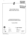
The bytes are transmitted in the sequence:
High Y, Low Y, High X, Low X. (See Diagram 2-2.)
After the ClRL ] and thef' ini tial four bytes have
been sent to the 5000 CRT controller, additional
bytes that do not change--except for the Low X
byte--need not be sent. If the High X byte is
changed then you MUST send the Low Y byte. The
release: 5/1/83
2-21
OMS-5000 Programmer's Manual
Low X byte must be sent each time to draw the
point or vector.
Once the line-drawing mode is entered, the
first coordinate pair received is treated as a
"dark vector," that is, a starting point for
subsequent plotting. For each pair sent after
that, a line will be drawn from the last point
received to the current coordinate. A nonplotting vector may be made by giving the plotmode code again (CTRL ] (Cl H) ), and sending a
new starting coordinate. Line-drawing mode is
exited and character mode entered by sending a
C"l'RL .. (l EH) •
By using the line-drawing mode, you can
place a character anywhere on the screen, not
only at row and column positions. Once in linedrawing mode, the four-byte coordinate pair for
the desired position of the character on the
screen is sent. The lower left-hand corner of
the character, descender excluded, is placed at
the pixel indicated by the coordinates. The
character's position can also be defined by
using the graphics mode report format. (Refer to
section 2.3.9 for specific information on
posi tioning characters on the screen.)
Once the coordinates have been sent,
exiting back to character mode will leave the
alpha cursor at the position of the last coordinates given. Characrers can then be entered at
that point. The next time a carriage return is
entered, the alpha cursor will home to the top
left of the screen. Therefore, after leaving
graphic mode, ~ carriage return should always be
issued before row and column addressing.
release:5jl/83
2-22
DMS-SOOO Programmer's Manual
10 BIT BINARY EQUIVALENT
TAG BITS
rL,
T
14TH BYTE
COORDINATE
PAIR
)_
~
HIGH Y
LOW Y
~~~:::::t
+
5000 CRT CONTROLLER
Diagram 2-2. Report format for the cursor position coordinates in graphic line-drawing mode.
release:S/l/83
2-23
DMS-5000 Programmer's Manual
The pixel limits of the DMS-5000 screen are
799 (decimal) on the X-axis, and 0 to 559
on the Y-axis. The lower left-hand corner of the
screen (in both orientations) is position (0,0).
In the interest of compatibility with the 4010,
all incoming coordinates are scaled down to fit
on the 5000 screen. For example, a line drawn
from the lower-left corner to the upper-right
corner would be transmitted as (0,0) to
(1023,780) since the limits of the 4010 screen
are 0 to 1023 (X) and 0 to 780 (Y).
o to
If a graphic application is being specifically written for the 5000, it is advisable to
do away with scaling altogether. Scaling takes
extra time and, because of round off error, it
is difficult to tell exactly what coordinates
will appear on the screen. If there is no reason
to use the 4010 screen coordinate limits,
coordinate scaling may be disabled or enabled
with the following codes:
ESC t (lBH,23H)
Disable coordinate scaling.
ESC % (lBH,25H)
Enable coordinate scaling.
Do
not exceed the coordinate limits. These are:
o-
ooo-
1023 for X and
780 for Y with scaling enabled.
799
559
for X and
for Y with scaling disabled.
Bit-mapped shapes that are too large for
the screen limits will be displayed wrapped
around the screen.
release: 5/1/83
2-24
DMS-5000 Programmer's Manual
NOTE---ESCAPE and CONTROL codes may be used
in graphic modes as well as character modes.
2.4.1 SHAPE DISPLAY AND SCREEN ORIENTATION
When the 5000 is mounted in the vertical
orientation, graphics coordinates that were
originally prepared for a horizontal screen will
still have their origin at the lower left hand
corner of the screen. The CRT controller will
rotate the coordinates to fit in the vertical
screen. The lower left-hand corner will be (0,0)
and the upper-right corner will be (559,799).
However, the shape's orientation will still be
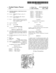
the same asit was in horizontal mode. Diagram
2-3 illustrates thiS-display feature. Any lines
with either or both end points off the screen
will be rejeCted and will not be di"SpIayed.
2.4.2 STATUS ENQUIRY
If a graphic application is being written
that is to be used in either orientation, a
STATUS ENQUIRY may be made of the 5000 that will
tell, among other things, the orientation in
which that the display is currently mounted.
ESC ENQ
(lBH,05H) Transmit status to host.
release: 5/1/83
2-25
OMS-5000 Programmer's Manual
(799,559) ,
'(1,559)
(799,1) ,
(0,0)
'(1,799)
(559,799)'
, (280,390)
(390,280)
A .
Diagram 2-3. Shape fill is independent of
screen orientation. Note how coordinates are
rotated to fit screen. (All coordinates are
approximate. )
release: 5/1/83
2-26
DMS-5000 Programmer's Manual
Upon receipt of the above escape code, the
5000 will transmit 6 bytes to the host controller. These are to be interpreted as follows:
1. Status byte
(x,y)
Cursor Position
2.
{ 3.
4.
5.
6.
High X
(5 bits)
Low X
(5 bits)
High Y
(5 bits)
Low Y
(5 bits)
Carriage Return
The status byte is read:
Bit 0- Orientation
Vertical = 1
Horizontal = 0
Bit 3- Unused
Bit 1- Video Display
Inverse Video = 1
Normal Video = 0
Bit 5- Always 1
Bit 2-
Bit 7- Always 0
Mode
Graphic = 1
Character = 0
Bit 4- Unused
Bit 6- Always 0
2.4.3 SCREEN WRITE MODES
When using any of the graphic functions
such as line drawing, point plotting, or block
filling, the logic with which the pixels are
plotted onto the screen may be set to one of
three modes. These modes may be selected wi th
the following escape codes:
release: 5/1/83
2-27
DMS-5000 Programmer's Manual
ESC I (1 BH, 7CH) "OR" Plot mode- each point
written to the screen will be written as a light
point. (This mode is the power-up default.)
ESC & (lBH,26H) "ANO" Plot mode- each point
written to the screen will be written as a dark
point.
ESC - (1BH,7EH) "XOR" Plot mode- each point
written to the screen will be the complement, at
that point, of whatever was previously on the
screen. (E.g., a light point will become a dark
point. )
2.5 POINT PLOT MODE
Point-plotting mode is entered using the
code CTRL \ (1 CH). Coordinates for pointplotting are formatted in the same way as in the
line-drawing mode and adhere to the same rules
concerning scaling and screen limits. One point
is plotted onto the screen for each four byte
coordinate pair received. The code CTRL .... (1 EH)
returns the CRT to character mode.
2.6 GRAPHIC-INPUT MODE
Graphic-input mode is implemented as an
emulation of the Tektronix 4010 GIN mode. To
enter this mode, transmit the codes ESC SOB
(1 BH, 1AH). When this command is received by the
CRT controller, the alpha cursor is replaced by
a full-size crosshair cursor. This cursor may be
release: 5/1/83
2-28
DMS-5000 Programmer's Manual
moved using the cursor control keypad on the
right hand side of the keyboard. Striking any of
the arrow keys will move the crosshairs one
pixel in the given direction. The cursor can be
moved diagonally by using the corner keys
(7,9,1,3). Holding down the shift key while
striking a cursor key will move the cursor 10
pixels at a time.
All of this cursor movement goes on
transparent to the host computer until any ASCII
key is struck. The CRT controller will then send
a six byte sequence to the host computer reporting the key struck and the position of the
crosshair cursor. The report format is as
follows:
Byte
Byte
Byte
Byte
Byte
Byte
1
2
3
4
5
6
-
Keyboard character
High X
Low X
High Y
Low Y
Carriage Return
Diagram 2-4 illustrates the report format
for the DMS-5000 in graphic input mode.
These coordinates are reported in the 4010
format and scaled to 4010 screen proportions.
The scaling may be disabled using the commands
described in Section 2.4, Line-Drawing Mode.
After the key that reports the cursor
position is struck, the 5000 controller will
exit graphic input mode and return to alpha
release: 5/1/83
2-29
DMS-SOOO Programmer's Manual
RESPONSE TO
5000 CPU
C~~~~~~~ \011111111 BYTE 1
~IGH X 101011111111 BYTE2
LOWX
\01110111111 BYTE3
HIGH Y
10\011111111 BYTE4
LOWY
101111111111 BYTES
CR
101010111111 BYTE6
CROSS·HAIR
CURSOR
COORDINATES
87654321
l~----..v___~)
BITS
REPORT FORMAT
CPU: ESC SUB
OPERATOR: 1) SETS CROSS·HAIR CURSOR
2) STRIKES KEY TO REPORT CURSOR POSITION
Diagram 2-4. The six-byte report format for the
crosshair cursor position in Graphic Input Mode.
release:S/l/83
2-30
DMS-5000 Programmer's Manual
mode. If the controller requires more data,
according to the applications program, it will
return to graphic input mode. This sequence is
the same as for the Tektronics 4010.
By using an ESC code you can control the
full screen crosshair cursor with an applications program. This will allow the control of
cursor movement by means other than the cursor
arrow keys on the 5000 numeric keypad (e.g.,
with a graphics pad or a trackball interfaced to
the host computer).
To use this feature send:
EOC G (lBH,47H) 4 byte coordinate (4010 format)
This will result in the graphic cursor
moving to the four-byte coordinate location.
2.6.1 BIT MAP BLOCK SCREEN FILL
The CRT screen can be loaded with a bitmapped picture transmitted as a stream of bytes
from the host processor. (See example in section
2.6.3.)
The first (x,y) coordinate transmitted is
the lower left-hand corner of the block on the
screen to be filled. The following bytes are
loaded onto the screen from left to right starting at that initial point. When the width limit
is reached, the fill commences on the next line
up. The CRT controller keeps count of the
incoming bytes and returns normal control to the
release: 5/1/83
2-31
DMS-5000 Prograrrmer' s Manual
host processor when the block is filled. The
transmission sequence is as follows:
1
2
3
4
5
6
7
8
9-N
ESC X (1 BH, 58H) Block fill code.
Y ooordinate--most significant byte.
Y coordinate--Ieast significant byte.
X coordinate--most significant byte.
X coordinate--Ieast significant byte.
Vertical height in pixels--most
significant byte.
Vertical height in pixels--Ieast significar
byte.
Horizontal width in bytes (x 8 pixels) --one
byte.
Bytes of bit
JDaR?9d block.
Each byte transmitted equals 8 pixels--1
bit equals 1 pixel. In the default write mode, a
o bit would be written as dark point and a 1 bit
would be a light point. (See section 2.4.3) The
first byte--a string of 8 pixels--is sent to the
CRT at the lower left-hand corner of the predefined block. Each succeeding byte fills in the
block from the left to the right until the first
row is filled. The next byte begins one row up
from the first, starting again at the left
corner.
2.6.2 SHAPE DISPLAY AND SCREEN ORIENTATION
The direction and sequence in which a shape
will fill on the screen is independent of the
screen orientation. A shape will always fill as
if it was being displayed in horizontal mode.
Therefore if a shape is to be displayed in
vertical mode, the block fill will begin in the
release: 5/1/83
2-32
DMS-5000 Programmer's Manual
upper left corner of the shape and fill downward
until it reaches the bottom of the shape. The
fill will then return to the top of the shape,
one pixel to the right of the first column, and
begin filling downward again.
Remember that even though the coordinates
are rotated when you change from horizontal to
vertical, the scan lines still run in the same
direction as in horizontal mode. Therefore the
shape will fill as if the screen was still in a
horizontal position. (Refer to Diagram 2-3.)
2.6.3 BIT MAPPED SHAPE MEMORIZATION
This feature enables the user to store a
given shape or symbol in the CRT controller for
repetitive use. The shape is loaded into the
controller in much the same fashion as a
function key string. The sequence to load the
shape is as follows:
1-2
3
4
5
6
7-N
ESC n (lBH,6EH) Shape load code.
Shape number ( 1 to 128)--one byte.
Vertical height in pixels--Ieast significant
byte.
Vertical height in pixels--most significant
byte.
Horizontal width in bytes (x 8 pixels)--one
byte.
Bytes of bit-mag;led block.
release: 5/1/83
2-33
DMS-5000 Programmer's Manual
For example, sending the sequence:
~-----------------------
lBH 6:m
....c:
01H
shape load code
shape number
08H OOH
I
I
02H
T
vertical heightin pixels
horizontal bytein 8 pixel units
FFH FFH 7FH FEH
3FH FCH lFH F8H
OFH 7CH 07H 3EH .....- - - - - - b i t mapped block
03H lFH 01H OFH
will cause this 8 pixel x 16 pixel shape to be
memorized:
Once the shape is loaded into memory, the.
screen coordinates where the user wishes the
shape to appear are given by entering the linedrawing mode (C'l'RL ]) and sending the four-byte
coordinate sequence. To write the shape onto the
screen the user will send the following
sequence:
m=
@
(lBH,40H) Shape nDher
The shape will fill up and to the right
until its size limits are reached. If the shape
release: 5/1/83
2-34
DMS-5000 Programmer's Manual
is too large for the screen (e.g., a full screen
horizontal shape displayed on a verticallyorientated screen), then the shape will wrap
around to the other edge of the screen.
(Remember, this is not the case in Line Drawing
Mode. Lines that have origins or endpoints
beyond the screen limits will not be displayed
at all.)
Up to 128 shapes may be memori zed at a
time. Shapes may be UP TO 253 BYTES LONG and no
longer. The shape buffer has a storage limit of
3K. If too many large shapes are loaded and the
buffer is over-filled, the 5000 cannot be
guaranteed to function properly.
2.6.4 PRINTING GRAPHICS
Graphics can only be printed using the
screen-dump commands. Only parallel printers
wi th graphics formats similar to the ones
specified here can be used for a graphICs screen
dump.
- - -- - -- -- A screen dump can be initiated from either
the keyboard or from an applications program.
From the keyboard use CTRL/SHIFT F8 and F9.
CTRL/SHIFT Fa - Graphics screen dump to Epson
MX-100, or equivalent, on parallel
port.
CTRL/SHIFT F9 - Graphics screen dump to Okidata
Microline 83A, or equivalent, on
parallel port.
release: 5/1/83
2-35
DMS-5000 Programmer's Manual
ESC ETB (1 BH, 17H) - Graphics screen dump to
Epson MX-100 on parallel
port.
ESC
~
(lBH,18H) - Graphics screen dump to
Okidata Microline 83A on
parallel port.
If a printer is not attached to the parallel print port or if the printer is not turned
on when the screen dump keys are used, the 5000
will wait for 12 seconds, emit a short beep and
then exit screen dump mode.
See Appendix C for information on the
parallel port pin assignments.
PRINTING TEXT WITH SERIAL PRINTERS
For information on the 5000's serial and
parallel printer ports and HiNet's I/O byte
structure, see Appendix C.
release: 5/1 /83
2-36
DMS-5000 Programmer's Manual
3.0 PROGRAMMABLE FUNCTION KEYS
Across the top of the keyboard are sixteen
function keys. Each are programmable with up to
three separate strings of variable length. In
addition, the ten numeric keys, the decimal
point key on the numeric/cursor-control keypad
and the three blank keys in the main key group,
are all programmable. Each key may hold three
separate values, one for the key alone, one for
the key with the SHIFT key held down, and one
for the key with the CTRL key held down. This
gives you 90 programmable keys in all. Diagram
3-1 shows you which keys are programmable
function keys.
Upon startup, the top row of function keys
are initialized with the following HiNet-CP/M
corrmands:
Key
Fl
F2
F3
F4
F5
F6
F7
F8
Key
F9
Command
Assign
Dir
Pip
Stat
FlO
Fll
F12
Type
F13
Submit
Ren
Era
F14
F15
F16
Cornrnarrl
Load
Save
Setbaud
Settime
Time
Customiz
Dirnet
Who
The CTRL and SHIFT values of the sixteen
programmable keys are left null.
release: 5/1/83
3-1
DMS-5000 Programmer's Manual
_---A'-------..
(
1
Diagram 3-1. An illustration of the 5000 keyboard with all programmable function keys labele
release: 5/1/83
3-2
DMS-5000 Programmer's Manual
Also upon startup, the eleven keys of the
right-hand keypad are initialized with numeric
values according to their legends. (The decimal
point is programmed with a period. "ENTER" is a
permanent, non-programmable carriage return.)
The shifted values of the arrow keys are
programmed with cursor control codes:
UP
- CTRL Z (l AH)
DOWN - LINE FEED (OAH)
LEFT - BACKSPACE (08H)
RIGHT- CTRL F (06H)
The control values for the numeric keys are
left nUll.
To reprogram the function key output
strings the following code is used:
EOC 1
function key number
length of string
string
3.1 FUNCTION KEY NUMBER
"Function key number" is the one-byte
binary identifier of the function key you want
to program. To calculate the function. key number
of a function key, add the hex value of the key
(e.g., F1 =1 H, F1 6=1 OH) to 80H. For example, the
function key number for F17 is:
17=llH
release:5/1/83
llH + 80H = 91H
F17=91H.
3-3
DMS-sOOO Programmer's Manual
To program the SHIFTED value of a function
key, set bit 5 in its function-key number byte
to one. To program the CONTROL value of a key,
set bit 6 in the byte to one. See Diagram 3-2
for the byte structure of the function key
numbers.
To find the function key number for the
shifted value of a function key, add AOH to the
key number. For example:
SHIFT/F6
= 6+
AOH
= A6H
To find the function key number for a
CTRL/Function key, add COH to the key number.
FOr example:
CTgL/F6
= 6+ COH = C6H
As another example, if you wanted to
program key FlO to output the string:
Hi There!
the programming command would look like this:
~-----------------key
number
ll------length
m:
1 (1 BH,6CH) BAH 9H Hi '!'bere!
1
....------- string
release: 5/1 /83
DMS-5000 Programmer's Manual
In BASIC the program code would be:
10 PRINT CHR$ (lBH) ;CHR$ (6CH) ;CHR$ (8AH) ;CHR$ (9H) ;
20 PRINT Hi There!;
The maximum buffer space allotted to
function keys is lk Hex bytes. Each function key
can be programmed with a maximum of 125
characters.
3.1.1 FUNCTION KEY NUMBER REPORT
Normally, when a function key is pressed,
the string programmed into it is sent to the
host CPU. A mode can be entered in which only
the function key number (in hex) will be
reported to the host CPU when a function key is
pressed. For example, Fl will send 81H and F6
will send 86H.
ESC P (lBH,70H) - Report function key number
only.
ESC P (lBH,50H) - Report function key's
programmed str ing.
release: 5/1/83
3-5
DMS-5000 Programmer's Manual
BYTE STRUCTURE FOR FUNCTION KEYS
SHIFT
CTRL
FUNCTION
F1 (81 HEX) 11101010101010111
8H
1H
F6 (86 HEX) 11101010101111101
8H
6H
SHIFT F6
b[01110101 111101
AH
6H
CTRL F611111010101111101
CH
6H
[NUME~69J:~H~ 11101011101011111
9H
3H
Diagram 3-2. Byte structure of the Function
Keys and examples for calculating the Function
Key Number.
• For all function keys, bit 7 is set to 1.
• Bit 6 is set to 1 only for the CTRL value of
a key.
• Bit 5 is set to 1 only for the SHIFT value of
a key.
• Bits 4 through 0 are for the hex value of the
function key label.
release: 5/1/83
3-6
OMS-5000 Programmer's Manual
4.0 DMS-5000 CRT CONTROL CODES SUMMARY
Release Version 1.2
4.1 SCREEN BRIGHTNESS CONTROL
The screen brightness is controlled locally
by holding down the control and shift keys while
striking a function key as follows:
CTRL/SHIFT F1
Turns screen br ightness down
one increment.
CTRL/SHIFT F2
Turns screen brightness up
one increment.
Alternatively, the intensity may be stepped
up or down by the host computer with the
following codes:
ESC b (lBH,62H) Turns screen brightness up
one increment.
ESC d (lBH,64H) Turns screen brightness down
one increment.
4.2 CHARACTER ENHANCEMENT CONTROL
ESC R (lBH,52H) Turns character inverse video
on for all following
characters.
Release: 5/1/83
4-1
DMS-5000 programmer's Manual
ESC U (lBH,55H) Turns underline on for all
following characters.
ESC 0 (lBH,4FH) Turns on character overstrike
mode.
ESC N (lBH,4EH) Returns all following
characters to normal.
ESC T (lBH,54H) Full screen inverse video.
4.3 HORIZ. MODE CHARACTER SIZE SELECTION
ESC S (lBH,53H) Select small characters.
(132 x 50)
ESC H (lBH,48H) Select large characters.
(80 x 24)
ESC v (1BH,76H) Sets a horizontally orientated
screen to display in vertical
mode.
4.4 CURSOR DISPLAY CONTROLS
ESC D (1 BH,44H) Makes the cursor invisible.
ESC E (lBH,45H) Makes the cursor visible
again.
ESC f
(1 BH,66H) Non-flashing cursor.
ESC F (lBH,46H) Flashing cursor.
Release: 5/1/83
4-2
DMS-5000 Programmer's Manual
4.5 OCROLLIt«; CONTROL
ESC ( (1BH,28H) Turn scrolling off. (Home
cursor to end of screen.)
ESC ) (lBH,29H) Turn scrolling on.
ESC !
(lBH,21H) Scroll bottom three lines only.
4.6 GRAPHIC SCREEN WRITE MODES
These codes determine the screen plotting
logic. These modes are used for point-plotting,
line-drawing, block-filling and shape memorization functions. The default mode is 'OR'.
ESC
I (7CH)
"OR" Plot mode--each point written
to the screen will be written as
a light point.
ESC &(26H)
"AND" Plot mode--each point written
to the screen will be written as a
dark point.
ESC -(7EH)
''XOR'' Plot mode--each point written
to the screen will be the complement
of whatever was previously on the
screen.
release: 5/1/83
4-3
DMS-SOOO Programmer's Manual
4.7 BIT MAP BLOCK SCREEN FILL
The transmission sequence is as follows:
1
2
3
4
S
6
ESC X (lBH,S8H) Block fill code.
Y ooordinate--most significant byte.
Y coordinate--least significant byte.
X coordinate--most significant byte.
X coordinate--least significant byte.
Vertical height in pixels--most
significant byte.
Vertical height in pixels--least
significant byte.
Horizontal width in bytes (x 8 pixels)
--one byte.
Bytes of bit mapped block.
7
8
9-N
4.8 BIT MAPPED SHAPE MEMORIZATION
1-2
3
4
S
6
7-N
ESC n (lBH,6EH) Shape load code.
Shape ~
(1 to 128)--one byte
Vertical height in pixels--least
significant byte.
Vertical height in pixels--most significant byte.
Horizontal width in bytes (x 8 pixels)-one byte.
Bytes of bit-mapped block.
\ To write the shape onto the screen:
ESC
@
(1 BH, 40H) [Shape
release:S/l/83
nmiler]
4-4
DMS-5000 Programmer's Manual
4.9 CURSOR POSITIONING.CONTROL
Homes cursor to upper left
posi tion of screen.
CTRL A
(OlH)
CTRL L
(OCH)
Clears screen and homes
cursor.
backspace
Moves cursor one column left.
(CTRL H)
(08H) .
Moves cursor one column
right.
CTRL F
(06H)
linefeed
CTRL J
Moves cursor one line down.
(OAH)
CTRL z
(lAH)
Moves cursor one line up.
<CR>
Moves cursor to beginning of
current line.
(CTRL M)
(ODH)
ES! Y (lBH,59H) row+20h,col+20h
Set absolute cursor position.
Rowand column number must be in
hex.
release: 5/1/83
4-5
DMS-5000 Programmer's Manual
4.10 ALTERNATE CHARACTER SETS
ESC L (lBH,4CH) Character set code
Character set codes:
= HOLLAND
A = ASCII
H
B
D
I
N =
F
G
= BRITISH
=
DANISH
= FRENCH
= GERMAN
S
(DUTCH)
= ITALIAN
NORWEGIAN
= SWEDISH
ESC c
(lBH,63H)
Download character set.
ESC w
(lBH,77H)
Load keyboard transposi tior
table.
ESC x
(lBH,78H)
Reset transposition table
to default.
ESC
(lBH,27H)
Load character descender
table.
I
4.11 GRAPHIC LINE DRAWING MODE
Cl'RL [
(lDH)
Enter line-drawing mode.
Cl'RL
(1 EH)
Exit Line drawing mode to
character mode.
ESC
A
t
ESC %
scalin~
(lBH,23H)
Disable coordinate
(lBH,25H)
Enable coordinate scaling.
(Coordinate scaling is enabled on power up condition
release:5/1/83
4-6
DMS 5000 Programmer's Manual
4.12 GRAPHIC-INPUT MODE
In graphic-input mode, the crosshair
graphic cursor is displayed. Upon striking a
key, the key struck and the current coordinate
are reported to the host computer. (See section
2.6 for report format.)
The graphic cursor is controlled from the
right-hand keypad. The arrows on the keys
represent the direction of cursor movement.
Depressing an arrow key alone moves the cursor a
distance of one pixel. Holding down the shift
key along with the cursor key moves the cursor a
distance of ten pixels at one time. The corner
keys will move the cursor in a diagonal direction.
ESC CTRL
CTRL
A
Z
(1 EH)
(l BH, 1AH)
Enter graphic input mode
Exit to character mode.
4.13 PARALLEL PRINTER PORT ACCESS
ESC [
(lBH,5BH)
release: 5/1/83
Sends only the next character
to the printer. ESC [ must be sent
before every character that is
to be printed through the parallel
port. Characters are not displayed
on the screen.
4-7
DMS-SOOO Programmer's Manual
4.14 DMS-5000 TEST FUNCTIONS
The 5000 has two test functions built in for
service purposes. The 5000 must be reset to get
out of either of these functions.
IS: ?
(1BH,3FH)
Extended RAM test.
IS: DEL
(1BH,7FH)
Display alignment pattern.
4.15 LOCAL FUNCTIONS
.LocalfuncHons can be accessed from the
keyboard without interrupting the application
currently running. To use these functions, hold
down the CONTROL and SHIFT keys simultaneously
and strike a function key as follows:
C'rRL/SUFl' F1
Turns screen brightness
down one increment.
C'l'RL/SUFl' F2
Turns screen brightness
up one increment.
C'.l'RL/SHIPr F3
Swaps foreground and
background intensities.
Full screen reverse
video.
C'l"RL/SIllFl'.F4
Enter Monitor mode.
C'l'RL/SHIFT F5
Enter Local mode.
Cursor stops flashing.
release: 5/1/83
4-8
OMS-5000 Programmer's Manual
CTRL/SHIFT F6
Exi t Local mode.
Cursor resumes flashing.
CTRL/SHIFl' F7
Exit Monitor mode.
CTRL/SHIFT F8
Graphics screen dump to
printer for Epson MX-100
Printer on parallel
port.
CTRL/SHIFT F9
Graphics screen dump to
printer for Okidata
Microline 83A Printer
on parallel port.
C'l'RL/SHIFl' Fll
Turns on Half-Duplex Mode.
C'l'RL/SHIFl' F12
Turns on Full-Duplex Mode.
(Default operation mode.)
CTRL/SHIFl' F14
ASCII character set
test. (Printable
characters 20H-7FH.)
release: 5/1/83
4-9
DMS-5000 Programmer's Manual
5.0
CODE
ESCAPE AND CONTROL CODES INDEX
PAGE
DESCRIPTION
ESC b •••••• screen brightness up ••••••••••••••••• 4-1
ESC c •••••• download character set •••••••••• 2-11,4-6
ESC CAN •••• screen dump to Okidata •••••••••••••• 2-36
ESC d •••••• screen brightness down •••••••••••••• 4-1
ESC D•••••• invisible cursor ••••••••••••••••• 2-7,4-2
ESC DEL •••• display alignment pattern •••••••••••• 4-8
ESC E•••••• visible cursor ••••••••••••••••••• 2-7,4-2
ESC ENQ •••• transmit status to host ••••••••••••• 2-25
ESC ETB •••• screen dump to Epson MX-100 ••••••••• 2-36
ESC f •••••• non-flashing cursor •••••••••••••• 2-7,4-2
ESC F •••••• flashing cursor ••••••••••••••••• 2-31,4-2
ESC G•••••• graphics cursor-control from host ••• 2-28
ESC H•••••• 80x24 line format •••••••••••••••• 2-3,4-2
ESC K•••••• clear to end of line ••••••••••••••••• 2-5
ESC k •••••• clear to end of screen ••••••••••••••• 2-5
ESC l •••••• function-key program mode •••••••• 3-3,2-4
ESC L•••••• char"acter set access •••••••••••••••• 2-1 0
ESC n •••••• memorized shape load code ••••••• 2-33,4-4
ESC N•••••• sets characters to normal •••••••• 2-7,4-2
ESC O•••••• character overwrite mode ••••••••• 2-7,4-2
ESC P •••••• report function key string mode •••••• 3-5
ESC p •••••• report function key number mode •••••• 3-5
ESC Q•••••• monitor mode on •••••••••••••••••••••• 2-1
ESC q •••••• monitor mode off, return to FDX •••••• 2-2
ESC R•••••• inverse video on ••••••••••••••••• 2-6,4-1
ESC S •••••• small character format ••••••••••• 2-3,4-2
ESC SUB •••• enter graphic-input mode •••••••••••• 2-28
ESC T•••••• toggles full screen inverse video •••• 2-7
ESC U•••••• underline on ••••••••••••••••••••• 2-7,4-2
ESC v •••••• vert. mode char in horz. orientation.2-4
ESC w•••••• keyboard transposition table •••• 2-19,4-6
ESC x •••••• reset transposition table ••••••• 2-19,4-6
ESC X•••••• block-fill code ••••••••••••••••• 2-32,4-4
release: 5/1/83
5-1
DMS-5000 Programmer's Manual
EOC
ESC
EOC
ESC
ESC
ESC
ESC
ESC
ESC
ESC
ESC
EOC
ESC
ESC
ESC
ESC
y •••••• set absolute cursor position ••••• 2-6,4-5
CTRL Z.graphic-input mode ••••••••••••••••••• 4-7
@•••••• display memorized shape ••••••••• 2-34,4-7
[ •••••• sends next character to II printer ••• 4-7
# •••••• disablecoordinate scaling •••••• 2-24,4-6
%•••••• enable coordinate scaling ••••••• 2-24,4-6
I....•. point written as light point •••• 2-2S,4.-3
&•••••• point written as dark point ••••• 2-2S,4-3
- •••••• point written as carnplement ••••• 2-2S,4-3
( •••••• turns scrolling off •••••••••••••• 2-9,4-3
) •••••• turns scrolling on •••••••••••••• 2-10,4-3
! •••••• scrollbottom 3 lines only •••••• 2-10,4-3
' •••••• load chara9ter descender table •• 2-1S,4-6
; •••••• 26 line display •••••••••••••••••••••• 2-4
: •••••• 24 line display ........................ 2-4
exteooed ram .test •••••••••••••••••••• 4-8
#to • • • • • . •
CONTROL CODES INDEX
CTRL
CTRL
CTRL
CTRL
CTRL
. . / CTRL
y.
CTRL
CTRL
CTRL
CTRL
A•••••••• cursor to upper left •••••••••• 2-5,4-5
F •••••••• cursor one column right ••••••• 2-5,4-5
H•••••••• cursor one column left •••••••• 2-5,4-5
J •••••••• linefeed •••••••••••••••••••••••••• 4-5
L•••••••• clears screen,homes cursor •••• 2-5,4-5 .
M «CR» .cursor to start of line ••••••• 2-6,4-5
Z•••••••• cursor one line up....... • ••• 2-6 , 4-5
] ......... line drawing mode ••••••• 2-21,2-34,4-6
............ exit to character mode •• 2-22,2-2S,4-7
\ •••••••• point plot mode •••••••••••••••••• 2-2S
CONTROL/SHIFT CODES INDEX
CTRLISHIFT
CTRLISHIFT
"'/CTRLISHIFT
CTRLISHIFT
v'
v
F1 ••• screen brightness down •••••• 4-1 ,4-S
F2 ••• screen brightness up •••••••• 4-1,4-S
F3 ••• reverse video ••••••••••••••••••• 4~S
F4 ••• enter monitor mode •••••••••• 2-2,4-S"'-
release:- 5/1 183
5-2
DMS 5000 Programmer's Manual
CTRL/SHIFT
CTRL/SHIFT
CTRL/SHIFT
CTRL/SHIFT
CTRL/SHIFT
CTRL/SHIFT
CTRL/SHIFT
CTRL/SHIFT
F5 ••• enter local mode •••••••••••••••• 4-9
F6 ••• exit local mode ••••••••••••••••• 4-9
F7 ••• exit monitor mode ••••••••••• 2-2,4-9
F8 ••• Epson MX-100 printer ••••••• 2-35,4-9
F9 ••• 0kidata Microline printer •• 2-35,4-9
F11 •• Half Duplex Mode •••••••••••• 2-1,4-9
F12 •• Full Duplex Mode •••••••••••• 2-1,4-9
F14 •• ASCII character set test •••••••• 4-9
release: 5/1/83
5-3
DMS 5000 Prograrrmer's Hanual
These listings, when assembled, will create object files that
when transmitted to the 5000 console will install a character
set equivalent to the default character set on startup.
This character set is for the vertical orientation.
These codes initiate the download.
DB
OW
lBH,43H
VCSLEN
FSC,c - LOAD OlAR. SET CODE
LENGTH OF CHARACTER SET
Here are the character bit maps, in ASCII order starting with blank.
;
VCSET
DB
DB
DB
DB
DB
DB
DB
DB
DB
DB
DB
DB
DB
DB
DB
DB
DB
DB
DB
DB
DB
DB
DB
DB
DB
DB
DB
DB
DB
DB
DB
DB
DB
DB
DB
DB
DB
DB
DB
DB
DB
DB
OOH,OOH,OOH,OOH,OOH,OOH
OOH,OOH,OOH,OOH,7BH,OOH
OOH,00H,70H,OOH,70H,00H
OOH,14H,7FH,14H,7FH,14H
OOH,12H,2AH,7FH,2AH,24H
OOH,62H,64H,8H,13H,23H
00H,37H,49H,35H,2H,5H
OOH,OOH,OOH,70H,OOH,OOH
00H,lCH,22H,41H,00H,OOH
OOH,OOH,OOH,41H,22H,lCH
00H,22H,14H,7FH,14H,22H
OOH,8H,8H,3EH,8H,8H
00H,OOH,02H,OCH,OOH,OOH
OOH,8H,8H,8H,BH,BH
00H,00H,OOH,3H,00H,OOH
OOH,2H,4H,BH,lOH,20H
OOH,3EH,45H,49H,51H,3EH
OOH,OOH,21H,7FH,lH,OOH
OOH,23H,45H,49H,49H,31H
OOH,42H,41H,49H,59H,66H
OOH,OCH,14H,24H,7FH,4H
OOH,79H,49H,49H,49H,46H
00H,lEH,29H,49H,49H,46H
00H,40H,47H,4BH,50H,60H
OOH,36H,49H,49H,49H,36H
OOH,31H,49H,49H,49H,3EH
OOH,OOH,OOH,6CH,OOH,OOH
OOH,OOH,lH,66H,OOH,OOH
OOH,BH,14H,22H,41H,00H
OOH,14H,14H,14H,14H,14H
OOH,41H,22H,14H,BH,00H
OOH,20H,40H,4DH,50H,20H
OOH,3EH,41H,5DH,4DH,39H
OOH,lFH,24H,44H,24H,lFH
00H,7FH,49H,49H,49H,36H
OOH,3EH,41H,41H,41H,22H
OOH,7FH,41H,41H,41H,3EH
OOH,7FH,49H,49H,49H,41H
00H,7FH,4BH,4BH,4BH,40H
OOH,3EH,41H,41H,45H,47H
OOH,7FH,BH,BH,BH,7FH
OOH,OOH,41H,7FH,41H,OOH
release: 5/1/83
;blank
!
"
#
$
%
&
single
I
(
)
,. *
+
comna
minus
/
0
1
2
3
4
5
6
7
B
9
<
>
?
@
A
B
C
D
E
F
G
H
I
A/A-1
DMS 5000 Programmer's Manual
DB
DB
DB
DB
DB
DB
DB
DB
DB
DB
DB
DB
DB
DB
DB
DB
DB
DB
DB
DB
DB
DB
DB
DB
DB
DB
DB
DB
DB
DB
DB
DB
DB
DB
DB
DB
DB
DB
DB
DB
DB
DB
DB
DB
DB
DB
DB
DB
DB
DB
DB
DB
DB
DB
VCSLEN . EQU
OOH,2H, lH, lH, lH, 7EH
00H,7FH,BH,14H,22H,41H
OOH, 7FH, lH, lH, lH, lH
00H,7FH,20H,10H,20H,7FH
00H,7FH,10H,BH,4H,7FH
00H,3EH,41H,41H,41H,3EH
00H,7FH,4BH,4BH,4BH,30H
00H,3EH,41H,45H,42H,3DH
00H,7FH,4BH,4CH,4A11,31H
00H,32H,49H,49H,49H,26H
00H,40H;40H,7FH,40H,40H
OOH, 7EH, 1H, 1H, 1H, 7m
00H,7CH,2H,lH,2H,7CH
00H,7FH,2H,4H,2H,7FH
00H,63H,14H,BH,14H,63H
00H,60H,10H,OFH,10H,60H
00H,43H,45H,49H,51H,61H
00H,7FH,41H,41H,41H,00H
00H,20H,lOH,BH,4H,2H
00H,41H,41H,41H,7FH,OOH
00H,BH,10H,3FH,10H,BH
OOH,l ,1 ,1 ,1 ,1
OOH, 40H, 201'1, 1OH,OOH,OOH
OOH,OEII, 11 H;l1H,OAII, lFH
OOH, 7FH,OAII, llH, 11H,om
OOH,OEH, 11,H, 11 H, 11 H, 11 H
OOH,OEII, 11H', 11 H, OAII, 7FH
00H,OEH,15H,15H,15H,OCH
00H,00H,BH,3FH,4BH,48H
00H,3BH,45H,45H,45H,7EH
00H,7FH,BH,10H,10H,OFH
OOH,OOH, 11 H,5FH, 1H,OOH
00H,2H,lH,lH,5m,00H
OOH,7FH,4H,OCH,12H,21H
00H,00H,41H,7FH,lH,OOH
OOH, lFH,l OH,OFH, 10H,OFH
00H,lFH,BH,10H,10H,OFH
00H,OEH,11H,11H,11H,om
00H,7FH,44H,44H,44H,38H
00H,38H,44H,44H,7EH,lH
00H,lFH,BH,10H,10H,10H
00H,9H,15H,15H,15H,12H
00H,10H,7m,11H,11H,2H
OOH,lEH,lH,lH,lH,lFH
00H,lBH,6H,lH,6H,18H
00H,lEH,lH,2H,lH,lm
00H,11H,OAII,4H,OAII,11H
00H,7BH,5H,5H,5H,7m
OOH, 11 H, 13H, 151'1, 19H, 11H
00H,00H,BH,37H,41H;00H
00H,00H,00H,7FH,00H,00H
00H,00H,41H,37H,BH,00H
00H,4H,8H,8H,8H,10H
00H,24H,49H,12H,24H,49H
OFFSET $-QFFSET VCSET
release: 5/1/83
; J
; K
L
M
N
0
P
Q
R
S
T
U
; V
; W
; X
; Y
; Z
; [
;
/
; 1
;
uooerline
apostrophe
; a
; J>.
; c
; d
e
f
9
h
"i i
j
k
1
; m
n
; 0
P
q
r
s
t
u
v
w
x
y
z
{
!
DEL
; LENGTH OF VERTIcAL CSET
A/A-2
DMS 5000 Programmer's Manual
This character set is for the horizontal large character format.
Here is the initialization:
DB
DW
lBH,63H
HCSLm
c, START DOWNLOAD
LENTIl OF CHAR. SET
ESC
And here is the image:
;
HCSET
DB
DB
DB
DB
DB
DB
DB
DB
DB
DB
DB
DB
DB
DB
DB
DB
0,0,0,0,0,0,0,0,0,0,0,0,0,0
0, 18H, 18H, 18H, 18H, 18H, 18H, 18H, 18H, 18H,0,0, 18H, 18H
0,14H,14H,14H,14H,0,0,0,0,0,0,0,0,0
0,24H,24H,24H,24H,OFFH,24H,24H,24H,OFFH,24H,24H,24H,24H
0,8,8,3EH,49H,48H,48H,3EH,9,9,49H,3EH,8,8
0,0,OE2H,0A2H,OE4H,4,8,8,10H,10H,27H,25H,47H,40H
0,30H,48H,84H,84H,48H,30H,30H,49H,85H,82H,82H,45H,39H
0,8,8,8,8,0,0,0,0,0,0,0,0,0
0,6,8,10H,10H,20H,20H,20H,20H,20H,10H,10H,8,6
0,60H,10H,8,8,4,4,4,4,4,8,8,10H,60H
0,0,0,8,49H,2AH,lCH,lCH,2AH,49H,8,0,0,0
0,0,0,0,8,8,8,7FH,8,8,8,0,0,0
0,0,0,0,0,0,0,0,18H,18H,8,8,10H,0
0,0,0,0,0,0,0,7FH,0,0,O,0,0,0
0,0,0,0,0,0,0,0,0,0,0,0,18H,18H
0,1,2,2,4,4,8,8,10H,10H,20H,20H,40H,40H
;BLANK
i1
,.n
;#
;$
;%
;&
;S1~
;(
;)
,.*
;+
;<XH'IA
;-
,.
;1
;NUMER1CAL CHARACTERS
DB
DB
DB
DB
DB
DB
DB
DB
DB
DB
DB
DB
DB
DB
DB
DB
DB
DB
DB
DB
DB
DB
DB
DB
DB
DB
DB
DB
0,3CH,42H,42H,81H,83H,85H,89H,91H,OA1H,OC1H,42H,42H,3CH ;0
0,8,18H,28H,8,8,8,8,8',8,8,8,8,3EH
;1
0,3CH,42H,81H,81H,1,2,4,18H,60H,80H,80H,OF1H,8EH
;2
0,OFFH,81H,2,4,8,lCH,2,1, 1,1 ,81H,42H,3CH
;3
0,2,6,OAH,12H,22H,42H,82H,OFFH,2,2,2,2,7
;4
0,OFFH,81H,80H,80H,80H,OBCH,OC2H,1,1,1,81H,42H,3CH
;5
0,3CH,42H,81H,80H,80H,OBCH,OC2H,81H,81H,81H,81H,42H,3CH ;6
0,OFFH,81H,1,2,2,4,8,10H,10H,20H,20H,20H,18H
;7
0,3CH,42H,81H,81H,42H,3CH,42H,81H,81H,81H,81H,42H,3CH;8
0,3CH,42H,81H,81H,81H,81H,43H,3DH,1,1,81H,42H,3CH
;9
0,0,0, 18H,18H,0,0,0,0,0, 18H, 18H,0,0
,.
0,0,0, 18H, 18H,0,0,0,0,0, 18H, 18H,8, 10H
;;
0,2,4,8,10H,20H,40H,80H,40H,20H,10H,8,4,2
;<
0,0,0,0,0,0,7EH,0,0,7EH,0,0,0,0
;=
0,40H,20H,10H,8,4,2,1,2,4,8,10H,20H,40H
;>
0,3CH,42H,81H,1, 1,2,4,8,8,8,0,8,8
;?
0,3CH,42H,81H,81H,9DH,OA5H,OA5H,OA5H,9EH,80H,81H,42H,3CH;@
0,18H,24H,42H,42H,42H,42H,7EH,42H,42H,42H,42H,42H,OE7H;A
0,OFCH,42H,41H,41H,41H,42H,7CH,42H,41H,41H,41H,42H,OFCH ;B
0,3CH,42H,81H,81H,80H,80H,80H,80H,80H,81H,81H,42H,3CH;C
0,OFCH,42H,41H,41H,41H,41H,41H,41H,41H,41H,41H,42H,OFCH ;D
0,OFFH,41H,40H,40H,40H,40H,7CH,40H,40H,40H,40H,41H,OFFH ;E
0,OFFH,41H,40H,40H,40H,40H,7CH,40H,40H,40H,40H,40H,OEOH ;F[
0,3CH,42H,81H,81H,80H,80H,80H,80H,8FH,81H,81H,43H,3DH;G
0,OE7H,42H,42H,42H,42H,42H,7EH,42H,42H,42H,42H,42H,OE7H ;H
0,lCH,8,8,8,8,8,8,8,8,8,8,8,lCH'
;1
0,7,2,2,2,2,2,2,2,2,82H,82H,44H,38H
;J
0,OC3H,44H,44H,48H,48H,50H,50H,68H,68H,44H,44H,42H,OE3H ;K
release: 5/1/83
A/A-3
DMS 5000 Programmer's Manual
DB
DB
DB
DB
DB
DB
DB
DB
DB
DB
DB
DB
DB
DB
DB
0,70H,20H,20H,20H,20H,20H,20H,20H,20H,20H,20H,21H,7FH
;L
0,OC1H,63H,63H,55H,55H,49H,49H,41H,41H,41H,41H,41H,OE3H ;M
OOH,OC3H,41H,61H,61H,51H,51H,49H,49H,45H,45H,43H,43H,OE1HiN
0,3CH,42H,81H,81H,81H,81H,81H,81H,81H,81H,81H,42H,3CH
;0
0,OFCH,42H,41H,41H,41H,42H,7CH,40H,40H,40H,40H,40H,OEOH ;P
0,3CH,42H,81H,81H,81H,81H,81H,81H,85H,85H,82H,45H,39H
;0
0,OFCH,42H,41H,41H,41H,42H,7CH,44H,44H,42H,42H,41H,OE1H ;R
0,3CH,42H,81H,81H,80H,40H,3CH,2,1,81H,81H,42H,3CH
;S
0,7FH,49H,8,8,8,8,8,8,8,8,8,8,lCH
;T
0,OE3H,41H,41H,41H,41H,41H,41H,41H,41H,41H,41H,22H,lCH ;U
0,OE3H,41H,41H,41H,22H,22H,22H,14H,14H,14H,8,8,8
;V
0,ODBH,49H,49H,49H,49H,49H,49H,49H,49H,55H,55H,22H,22H ;W
O,OE3H,41H,22H,22H;14H,14H,8,14H,14H,22H,22H,41H,OE3H
iX
;Y
DB
0,OE3H,41H,22H,22H, 14H, 14H,8,8, 10H, 10H,20H,OAOH,40H
O,OFFH,82H,2,4,4,8,3CH,lOH,lOH,20H,20H,41H,OFFH
0,3CH,20H,20H,20H,20H,20H,20H,20H,20H,20H,20H,20H,3CH
0,40H,40H,20H,20H, 10H, 10H,8,8,4,4,2,2, 1
0,3CH,4,4,4,4,4,4,4,4,4,4,4,3CH
0,8, 1CH, 1CH,2AH,2AH,491l,49H,8,8,8,8,8,8
O,O,O,O,O,O,O,O,O,O,O,OFFH,O,O
0,18H,18H,10H,10H,8,0,0,0,0,0,0,0,0
O,O,O,O,O,O,-7CH,2,2,7EH,82H,82H,82H,7DH
0,OCOH,40H,40H,40H,40H,SCH,62H,41H,41H,41H,41H,62H,ODCH
O,O,O,O,O,O,3CH,42H,81H,80H,80H,81H,42H,3CH
O,6,2,2,2,2,3AH,46H,82H,82H,82H,82H,46H,3BH
O,O,O,O,O,O,3CH,42H,81H,OFFH,80H,80H,41H,3EH
0,OEH,11H,11H,10H,10H,7EH,10H,10H,10H,10H,10H,10H,38H
0,0 ,3BH,44H,82H,82H,44H,OB8H,80H,7CH, 82H,81 H,81 H, 7EH'
0,OCOH,40H,40H,40H,40H,SCH,62H,41H,41H,41H,411l,41H,OC3H
0,0,0,8,8,0,18H,8,8,8,8,8,8,lCH
0,4,0,OCH,4,4,4,4,4,4,84H,84H,44H,38H
0,OCOH,40H,40H,40H,40H,43H,44H,48H,50H,68H,44H,42H,OC1H
0,18H,8,8,8,8,8,8,8,8,8,8,8,lCH
O,O,O,O,O,O,OD6H,69H,49H,49H,49H,49H,49H,ODBH
0,0,0,0,0,0 ,ODCH,62H,41 H,41 H,41 H,41 H,41 H,OC3H
O,O,O,O,O,O,3CH,42H,81H,81H,81H,81H,42H,3CH
0,0,ODCH,62H,41H,41H,41H,41H,62H,SCH,401l,40H,40H,OCOH
0,0,3AH,46H,82H,82H,82H,82H,46H,3AH,2,2,2,7
DB
0,0,0,0 ,O,O,OCEH,Sl H,61 H,40H,'40H,40H,40H,OEOH
DB
O,O,O,O,O,O,7EH,81H,80H,7EH,1,1,81H,7EH
0,0,0,1 OH, 1OH, 1OH, 7EH, 1OH, 10H,1 OH, 1OH, 11 H, 11 H,OEH
0,0,0,0,0,0,OC6H,42H,42H,42H,42H,42H,26H,lBH
0,0,0,0,0,0 ,OC3H,41 H,41 H,22H,22H, 14H, 14H,8
DB
DB
DB
DB
DB
DB
DB
DB
DB
DB
DB
DB
DB
DB
DB
DB
DB
DB
DB
DB
DB
DB
DB
DB
DB
DB
DB
DB
DB
DB
DB
DB
DB
DB
DB
OCSLEN EQU
0,0 ,0 ,a', 0, 0 ,ODBH, 49H, 49H, 49H, 55H, 55H, 22H, 22H
ia
;b
iC
;d
;e
;f
;9
;h
;i
;j
;k
;1
im
;n
;0
;P
;q
;r
is
;t
;u
;v
iW
O,O,O,O,O,O,OC3H,42H,24H,lSH,18H,24H,42H,OC3H
0,0,OC3H,41H,41H,41H,22H,22H,14H,14H,8,8,90H,60H
O,O,O,O,O,O,OFFH,82H,4,SH,10H,20H,41H,OFFH
0,OEH,10H,20H,20H,20H,20H,40H,20H,20H,20H,20H,10H,OEH
0,8,8,8,8,8,8,8,8,8,8,8,8,8
0,70H,8,4,4,4,4,2,4,4,4,4,8,70H
0,0,0,0,0,0,6,89H,91H,60H,0,0,0,0
0,55H,OAAH,55H,OAAH,55H,OAAH,55H,OAAH,55H,OAAH,55H,OAAH
55H,0
(OFFSET $) -HCSADD
; LENGTH OF HORIZONTAL CSET
release: 5/1/83
iZ
;[
;\
;]
;UPAR
;ULIN
;APOS
A/A-4
iX
;y
iZ
;{
:,"1
}
;
;HLF
DMS-5000 Programmer's Manual
APPENDIX B
Displayed
Character
NU
SH
Sx
MONITOR MODE CODE ABBREVIATIONS
ASCII
Character
EQ
AK
BL
BS
BS
~
HT
VT
FF
CR
So
SI
VT
00
01
02
03
04
05
06
07
08
09
OA
OB
FE'
OC
CR
SO
SI
DLE
OD
OE
OF
10
Ex
~
Lp
~
NULL
SOH
STX
ETX
Hex
Code
EOT
ENQ
ACK
BEL
LF
D1
D2
D3
D4
NK
Dl
11
D2
D3
D4
NAK
12
14
15
Sy
SYN
16
E13
ETB
17
CN
CAN
EM
EM
18
19
release: 5/1/83
13
Description
Null character
start of heading
start of text
end of text
end of transmission
enquiry
acknowledge
bell
backspace
horizontal tab
li ne feed
vertical tab
forrnfeed
carriage return
shift out
shift in
data link escape
device control 1
device control 2
device control 3
device control 4
negative acknowledgment
synchronous idle
end transmitted
block
cancel
end of medium
A/B-l
DMS 5000 Programmer's Manual
Sa
Fe
FS
GS
RS
Us
SUB
ESC
FS
GS
RS
US
SP
DEL
release: 5/1/83
1A
1B
1C
1D
1E
1F
20
7F
substitute
escape
file separator
group separator
record separator
unit separator
space
delete
A/B-2
DMS 5000 Programmer's Manual
APPENDI~
C
PRINTER CONNECTIONS
RS-232 CRT CONTROLLER BOARD JUMPER CONNECTIONS
The chart on pages C-2 and C-3 shows the
correspondence between pins on the CRT board
connectors, the CRT board jumper blocks, and the
ZSBC board for each of the three serial I/O ports.
This information can be used to construct a cable
and/or jumper block to connect a printer to the DMS5000.
Zilog's names for pin abbreviations
RxD Receive Data
TxD Transmit Data
CTS Clear to send
RTS Request to send
DTR Data terminal ready
DCD Data carrier detected
See the Zilog SIO Technical Manual or ZILOG
82/83 Data Book for pin descriptions.
Serial port 1 (CRT board connector G2) is the
HiNet port.
release: 5/1/83
A/C-1
Serial port 0 (CRT board connector G5)
H
CD
......
CRT board
DB25S (G5)
re
~
111
'::::i
pin
pin
pin
pin
pin
pin
pin
pin
pin
"
00
W
1
2
3
4
5
6
7
8
20
CRT Board
jumper block
G9 on CRT brd
J1 on ZSBC3
J6 on HNS86
ZSBC 3 Pinouts
~
HNS86 Pinouts
111
o
o
o
s~
chassis gnd
no jumper blk
for port 0
signal ground
pin 3
pin 5
pin 1
pin 10
pin 6
pin 13
no connect
pin 2
U2 pin 4
U1 pin 6
no connect
pu11up
pu11up
logic
RxD I
TxD 0
CTS I
RTS 0
DTRO
GND
no connect DCD
12Fpin1
12G pin 3
no connect
pu 11 up
pu11up
logic
RXD
TXD
CTS
RTS
DTR
I
0
I
0
0
t:Il
no connect DCD
Serial port 2 (CRT board connector G3)
CRT Board
jumper block
at U3
CRT board
DB25S (G3)
~
?N
pin
pin
pin
pin
pin
pin
pin
pin
pin
pin
pin
1
2
3
4
5
6
7
8
11
14
20
G9 on CRT brd
J1 on ZSBC3
J6 on HNS86
chassis goo
pin 17
pin 1-pin 16
pin 24
pin 2-pin 15
pin 12
pin 3-pin 14
pin 18
pin 4-pin 13
pin 5-pin 12
pin 15
pin 13
signal ground
pin 7-pin 10 pu11up on CRTc
pin 8
pin 9
pin 11
pin 6-pin 11
-
ZSBC3 board
pinouts
HNS86
serial ports
!
5000
CRT controller
I
•
U2 pin 13 RxD
U1 pin 8 TxD
U4 pin 4 CTS
U3 pin 3 RTS
U1 pin 11 DTR
logic grourrl
U4 pin 13
I
0
I
0
0
F12 pin 13 RXD
G12 pin 11 TXD
F12 pin 10 CTS
G12 pin 8 RTS
G12 pin 6 DTR
logic grouOO
F12 pin 4 DCD I
DCD I
------
I
0
I
0
0
~
~-
-
-
~-
U10 pin 10 RXD
U26 pin 3 TXD
U11 pin 1OCTS
U26 pin 8 RTS
U26 pin 6 DTR
logic grourrl
I
0
I
0
0
!
U10 pin 13 DCD I
---------
I.
!
H
GND
-------
......
~
1""1
ill
I-'
m
111
o
o
CJ)
ill
o
~
-'
~
~
'-...
00
Serial port 3 (CRT board connector G4)
w
CRT board
DB25S (G4)
CRT Board
jumper block
G9 on CRT brd
J1 on ZSOC 3
J6 on HNS86
ZSBC 3 brd
serial ports
HNS86 board
serial ports
5000
CRT controller
i
!
K
CJ)
pin
pin
pin
pin
pin
pin
pin
pin
pin
pin
pin
~
?w
1
2
3
4
5
6
7
8
11
14
20
pin 1-pin 16
pin 2-pin 15
pin 3-pin .14
pin 4-pin 13
pin 5-pin 12
signal ground
pin 7-pin 10
pin 8
pin 9
pin 6-pin 11
pin 21
pin 25
pin 20
pin 26
pin 23
pin 13
pullup on CRTc
pin 22
U2 pin 10 RxD
U3 pin 8 TxD
U4pin 1 CTS
U3 pin 11 RTS
U3 pin 6 DTR
logic ground
E12 pin 10 RXD
C12 pin 8 TXD
E12 pin 1 CTS
C12 pin 3 RTS
C12 pin 6 DTR
log ic ground
U4 pin 10
E12 pin 4 DCD I
DCD
I
0
I
0
0
U11 pin 1 RXD
U27 pin 8 TXD
U10 pin 4 CTS
U27 pin 3 RTS
U27 pin 6 DTR
logic ground
I
0
I
0
0
U10 pin 1 DCD I
I-'
OMS 5000 Programmer's Manual
HARDWIRED CONNECTIONS TO JUMPER BLOCK PINS
The following diagrams represent the two jumper
blocks on the CRT controller board, U3 and U14. For
each jumper block, refer to the previous tables for
the chip connections
Note---
X represents a 4.7K ohm resistor.
X
RxD TxD ers RTS DTR OCD +12
pin numbers of:
1111' II
on CRT board 17 24 12 18 15 11 19
X
J1 on ZSBC 3brd
X
J6 on HNS86 brd
G9
16
15
14
13
12
11
10
9
Jumper block for port 2
pin numbers of
DB25S (G3)
release: 5/1/83
2
3
4
5
6
20
8
11
A/C-4
14
OMS 5000 Programmer's Manual
RxD TxD CTS RTS DTR DCD +12
IIIIIII
pin numbers of
G4 on CRT board 21
J1 on ZSBC 3 brd
J6 on HNS86 brd
25
16
15
20
26
23
22
19
X
X
14
13
12
10
11
9
Jumper block for port 3
pin numbers of
DB25S (G4)
2
3
4
5
6 20
8
11
14
Pin layout and pin numbers for the G5 (CRT
board), G9 (CRT board), Jl (ZSCB 3 board), J6 (HNS86
board) and G37 Parallel port.
13
1
I
I
I
25
2
1
1
I
2
release: 5/1/83
G5 CRT
14
34
I
33
G9 CRT
J1 ZSCB-3
J6 HNS-86
49
I
50
G37 CRT Controller
A/C-5
DMS 5000 Programmer's Manual
Inside view of CRT controller board for DMS-5000
Series showing jwnper blocks and serial ports.
C~--~-----~J
!il
urO
U3-~
DDOD D
DDO D~ODDDDDDDDD
DO· 000000000000 0
D·
~ ~ DO 000DO 000D~
DODD DDDDDDDDD ODD
~~lnDDDDDDDDD DODD
~ ~ UODDDODODO DO
DDDDDO DDODDDDDDDOg
I
I
I
I
I
L,
L.. ___
"1... ____ ___, __ _ r--
release: 5/1/83
- -- - --
-"1- ________ .,
A/C-6
DMS 5000 Programmer's Manual
CHANGING JUMPER BLOCKS
1Turn off the DMS-5000 and disconnect the power
cord, keyboard, HiNet cable, and anything else
plugged into the uni t.
2Loosen the thumb-wheel on the base (clockwise
turn) and lift the DMS-5000 off of the base. Because
it fits tightly you may need to have someone hold
down the base while you lift off the unit. Place the
DMS-5000 face down (CRT down) on a clean table top.
MAKE SURE THERE IS NOTHING ON THE TABLE SURFACE THAT
CAN DAMAGE THE SCREEN.
3The back of the DMS-5000 should now be facing
up. Loosen the four screws that are in the middle of
the back of the cabinet. Lift off the cover straight
up. If the cover does not corne up easily the screws
need to be loosened some more.
4If the unit was in use immediately before
beginning opening the Case, allowS minutes to cool
with the cover off before proceeding.
5With the case removed you can see tl1e two green
circui t boards on the main chassis. One of them is
on the side next to the fan. The second circuit
board is away from the fan, and if the DMS-5000were
upright in the vertical operating mode this circuit
board would be at the bottom of the unit. This
bottom board is where the printer port jumper blocks
are located.
6Your body may be carrying a slight charge of
static electricity which might harm the circuit
board and chips when you handle the PROMs. Briefly
release: 5/1/83
A/C-7
OMS 5000 Programmer's Manual
touch the metal box that the circuit boards are
attached to, this will harmlessly drain off any
static electricity.
7- As you look at the board, the printer port
jumper blocks are located near the ports on the edge
of the board away from the casing around the screen.
See Diagram C-1. Both jumper blocks have 8 gold
coloured metal strips across them. They are labeled
on the board U3 and U14. U3 is for Port 2 and U14 is
for Port 3.
8To alter or replace a jumper block you must
first remove it from the board. Using a chip puller,
hook the feet of the puller under the jumper block's
rim and pull straight up. It will corne straight out
with no twisting or turning. Take care not to damage
any of the adjacent circuits. AVOID TOUCHING OTHER
PARTS OF THE UNIT, PARTICULARLY THOSE AREAS MARKED
'CAO'l'Im' •
9- Make the appropriate changes to the jumper block
or replace it with another one. One corner of a
jumper block is removed to indicate the orientation
of the block. The beveled corner must be positioned
in the upper left corner of the jumper block when
the block is inserted in the board and the board is
orientated as in Diagram C-1. The jumper block must
be inserted correctly or it will not function ---properly. Push the jumper block gently back into the
socket. Make sure none of the pins are bent or
twisted.
10- When the new jumper block is inserted, replace
the case and tighten the screws. Plug in the power
cord, HiNet cable, and keyboard.
release:5/1/83
A/C-8
OMS 5000 Programmer's Manual
EXAMPLES OF JUMPER BLOCKS
Jumper Block for a Texas Instruments 810 printer
The TI 810 printer has an onboard buffer. When
the buffer is full, the printer sends a busy signal
to the OMS-5000 by lowering OTR on RS-232 pin 20.
The serial I/O port on the ZSBC3 or HNS86 will stop
transmission automatically if this signal is
connected to its CTS input. This is accomplished by
connecting pin 14 to pin 6 instead of pin 3 on the
corresponding jumper block.
16
15
14
2
3
13
12
W
4
5
11
10
9
6
7
8
To order, use OMS part number: 90-7309
The ONE option on the TI 810 must be enabled by
setting the panel switches to:
1
234
low high high low
567
low high high
Remove the processor board of the printer
(green card ejectors) and jumper E5 to E6 instead of
E4. Verify that the resistor network near the
printer's RS-232 connector has not been pulled loose
before replacing the card cage enclosure.
NOTE---QUME and TI printers send the same
signals; the same jumper blocks can be used.
release: 5/1/83
A/C..,9
OMS 5000 Programmer's Manual
Jumper block for a Teletype model 40 printer
The teletype model 40 uses RS-232 pin 14 to
tell the computer that it is busy and no more
characters can be sent to it. This signal may be
connected to CTS on the proper serial I/O port of
the OMS-5000 by connecting pin 14 to pin 9 instead of
pin 3 on the corresponding jumper block on the CRT
board.
16
15 14
2
13
12
11
~ Iii
3
4
10
i
9
J
567
8
To order, use OMS part number: 90-7310
Jumper block for a standard modem
Most modems require the following pairs of
signals to be interchanged (compared to their
arrangement for a CRT): RxO and TxO, CTS and RTS,
and OCO and OTR.
16
15 14 13 12 11
10
9
7
8
XXX
1
2
3
4
5
6
To order, use OMS part number: 90-7311
release: 5/1/83
A/C-lO
OMS 5000 Programmer's Manual
PARALLEL PRINTER CABLE
The following table lists the pin connections
required to connect a DMS-5000 with a printer using
a parallel interface.
In the DMS-5000 Series, the parallel printer
interface is driven directly by the CRT controller.
It is accessed by preceeding each character sent to
the controller by ESC
(lBH,5FH). The CRT
controller will then pass the single character
following the ESC sequence to a printer, if there is
one connected. If no printer is connected, an internal
buffer will fill and no more characters will be
passed to the printer or to the CRT controller.
5000 CRT
controller
PDAT1
PDAT2
PDAT3
PDAT4
PDAT5
PDAT6
PDAT7
PDAT8
ACKI
BUSY
IN 401
GROUND
GROUND
GROUND
GROUND
GROUND
GROUND
GROUND
GROUND
GROUND
G37
Printer
Connector
Centronics
Signal Name
In or Out
of Printer
Pin
Pin
Pin
Pin
Pin
Pin
Pin
Pin
Pin
Pin
Pin
3
5
7
9
11
13
15
17
19
21
1
Pin
Pin
Pin
Pin
Pin
Pin
Pin
Pin
Pin
Pin
Pin
2
3
4
5
6
7
8
9
10
11
1
DATA 1
DATA 2
DATA 3
DATA 4
DATA 5
DATA 6
DATA 7
DATA 8
ACK
BUSY
DATA STROBEl
Input
Input
Input
Input
Input
Input
Input
Input
Output
Output
Input
Pin
Pin
Pin
Pin
Pin
Pin
Pin
Pin
Pin
2
4
6
8
10
12
14
16
22
Pin
Pin
Pin
Pin
Pin
Pin
Pin
Pin
Pin
19
20
21
22
23
24
25
26
29
DATA STB RET
DATA 1 RET
DATA 2 RET
DATA 3 RET
DATA 4 RET
DATA 5 RET
DATA 6 RET
DATA 7 RET
BUSY
Groun:J
Groun:J
Groun:J
Groun:J
Groun:J
Groun:J
Groun:J
Groun:J
Groun:J
release: 5/1/83
A/C-11
DMS 5000 Prograrrmer's Manual
I/O BYTE FOR HlNET
The INPUT/OUTPUT BYTE, at location 03h in
memory, is implemented for the mapping of logical to
physical devices. The mapping is perforJlled by
splitting the I/O BYTE into four distinct fields
called the CONSOLE, READER, PUNCH, and LIST fields,
as shown below.
Bit number:
7
Device name:
6
5
LST:
4
PUN:
3
--
1
2
RDR:
0
CON:
Whenever a reference to a logical device is
made for I/O, the BIOS first looks at the appropriate bit field in the I/O BYTE, and then uses one of
the physical device service routines. The following
table shows the association of I/O BYTE values with
physical devices.
Device
Name
CON:
RDR:
Physical
Device
Device Name
Used by STAT
00
01
10
11
serial port 0
serial port 2
parallel port2
serial port 3
CRT:
BAT:
0
serial port 0
serial port 3
TTY:
serial port 0
serial port 3
TTY:
bit
Value
1
PUN:
0
1
release: 5/1/83
TTY:
UCl :
PTR:
PTP:
A/C-12
OMS SOOO Programmer's Manual
HiNet versions 2.24S and previous will not allow
a printer to be assigned to the parallel port on the
DMS-SOOO Series.
"
The default for the LST: device can be changed
with ASSIGN. The other defaults can be changed by
using the STAT command. The default can be
permanently changed by following the customization
instructions in the HiNet manual.
The I/O byte values in the following table
assume that the Console is assigned to parallel port
2 (l 0), the Reader is assigned to serial port 3 (1)
and the Punch is assigned to serial port 3 (1). The
hex values will be different if the Console, Reader
and Punch are assigned to other ports.
List devices for OMS-3/F, OMS-1S, OMS-S080, DMS-S086
Device
LST:
Name
bits
Physical
Device
000
001
010
011
100
101
110
111
serial port 0
serial port 3
serial port 2
serial port 1
reserved
parallel port1
custan driver
HiNet spooler
LST:
IOBYTE value in:
binary
hex
0001
0011
0101
0111
0110
0110
0110
0110
1011 0110
1101 0110
1111 0110
16h
36h
56h
76h
--B6h
D6h
*
F6h
* Only for the Fox, no parallel printer port on others
release:S/1/83
A/C-13
DMS 5000 programmer's Manual
INDEX
bit map
transmission sequence, 2-32
bit mapped shape
buffer size
memory size, 2-35
wri ting shape
shape number, 2-34
bit mapped shapes
loading shape, 2-33
character display mode, 2-2
character enhancements
inverse video
underline
normal 1, 2-6
character sizesvertical orientation
horizontal orientation, 2-3
characters
European, 2-10
loading, 2-11
clear to end of line
clear to end of page, 2-5
control codes index, 5-2
control/shift code index, 5-2
coordinate limits, 2-24
crosshair cursor, 2-31
graphic input, 2-28
CRT display features, 1-2
cursor control
alpha mode, 2-5
release: 5/1/83
I-1
DMS 5000 Programmer's Manual
diagonal movement, 2-28
cursor display codes
visible
invisible
flashing
non-flashing, 2-7
descender tables, 2-18
escape codes index, 5-1
formats, 2-4
function key number, 3-3
function keys
buffer space, 3-5
programming
default assignments, 3-1
graphic problems, 2-9
graphics
mixed fonts, 2-9
graphics pad interfacing, 2-31
graphics problems, 2-8
half duplex mode, 2-1
horizontal large characters format, 2-12
horizontal small character format, 2-13
interlace inversion, 2-8
inverse video, 2-6
keyboard
changing layouts
transposition tables, 2-18
line drawing mode, 2-22
monitor mode, 2-1
pixel limits of screen, 2-24
plot modes
OR
AND
XOR, 2-28
report format
graphic input, 2-29
reverse video, 2-6
release: 5/1/83
1-2
DMS 5000 Programmer's Manual
scanning, 2-8
screen coordinates
transmission, 2-21
screen intensity
timeout function, 1-2
screen orientation, 1-1
status enquiry, 2-25
scrolling
counters
graphic problems, 2-8
disabling, 2-10
status byte, 2-27
status enquiry, 2-25
Tektronix 4010, 2-21, 2-28
scaling on the 5000, 2-24
trackball interfacing, 2-31
transposition table, 2-19
underline, 2-6
vertical display in horizontal mode, 2-4
vertical format characters, 2-15
release: 5/1/83
I-3
IHS-SOOO ~ MANUAL AOOF.HXlK
Changes to ESC codes.
NEW ESC eODE
OID ESC CODE
- - - ------
FUNCTION
To Disable Scaling
Large Horizontal Screen
(80x24)
ESC
PAGE NUMBERS
i
ESC
0'
(1 BH,22H)
2-24,4-6,5-2
H
ESC M
(lBH,4DH)
2-3,4-2,5-1
~
Reset Keyboard
Transposition Table
ESC x
ESC z
(lBH,7AH)
2-19,4-6,5-1
Extended RAM Test
ESC ?
ESC
(lBH,5EH)
4-8
Display Alignment
Pattern--~
Po
DEL, must be accessed in Local Mode
ESC < and ESC > are OMS in-house test functions and will 'crash;
the 5000 if used for any other reasons.
1
OMS-5000 Programmer's Manual
2. 7
SECOND PlANE GRAmICS
With the addition of a new 'daughter board' to
the CRT controller board, the OMS 5000 series is
capable of displaying characters and graphics in
different intensities.
2. 7. 1
WRITING 'lO A PlANE
Either plane can be written to by sending the
proper ESC code to the CRT controller. When a plane
is selected, the blink mode is automatically turned
off. Whatever is displayed on the other plane will
still be displayed. Therefore, to avoid any
undesired overlap, you should clear the screen
(ESC C or CTRL L) before chang ing planes.
}
(lBH,70H)
Write to plane 1 only
E&: {
(lBH,7BH)
Write to plane
ESC C
(lBH,43H)
Clear currently selected plane.
CTRL L
(OCH)
Clear both planes.
~
2.7.2
SETTING PlANE
2
only.
I~ITY
The intensity of the CRT display can be set
independently for each plane. There are 15 intensity
levels. A register holds the intensity values for
four combinations of planes. The levels are set by
sending the string:
Release: 3/1/84
2-1
OMS-5000 Programmer's Manual
ES! i nmn1 nmn2.
Num1 selects which combination of planes will be
effected. Num2 sets the intensity level. The fifteen
intensity levels are entered as Hex codes. OOH is
the highest intensity setting and OFH the lowest.
=
Num1
~
"
,~
~
f
0
1
2
3
plane 1
off
on
on
off
plane2
~ bo..c(c
+
register I intensity
o
2
3
06
03
03
OF
NOTE---If there is no daughter board, the 0
register has an intensity value of OF and the 1
register a value of 03. Plane 2 always appears to be
on.
Given these default intensity values, a pixel
that was turned:
on in plane 1 and off in plane 2 would be
displayed in full-intensity (06).
Release: 3/1/84
b'cl,1'\, , '
on
r-----P .-.~r-----t-'
on ----to re.
K.
off
"--Dre
off
-_______ -----~
~
The four intensity registers can be set to any
of the 15 levels. By default the levels are:
1
.
2-2
I
k'
OMS-SOOO Programmer's Manual
off in plane 1 and on in plane 2 would be
displayed in half-intensity (03).
on in plane 1 and on in plane 2 would be
displayed in full- intensi ty (06).
off in plane 1 and off in plane 2 would be
displayed in zero-intensity (OF).
Once you change the intensity values in the
register, they will stay that way until you change
them again or the 5000 is RESET.
For example, to display a bright graphic image
along with dim characters, set the intensities with
the sequence:
ESC i 2 0
(set plane one to bright intensity)
ESC i 0 8
(set plane two to dim intensity)
After the intensities are set, select plane one
(ESC} ) and write the graphic image. Then select
plane two (ESC { ) and write the characters that you
want to be displayed in half-intensity.
2.7.3
HALF-INTENSITY MODE
Sending an ESC H (lBH,48H) causes characters to
be written in half-intensity. This is done by
lowering the intensity of the back plane relative to
the front plane. All characters are then written
only to the back plane.
Both ESC H and ESC B will automatically set the
screen to character mode.
Release: 3/1/84
2-3
OMS-SOOO Programmer's Manual
ESC N (lBH, 4EH) will return the display to
rlonmal display mode.
NOTE---You cannot use both blinking and halfintensity displays at the same time. Either mode can
be used with character inverse, underline and
overstrike modes.
ADJUSTING HALF-INTENSITY
The half-intensity setting can be adjusted
either with a CTRL/SHIFT function key or by sending
an ESC code. Each time CTRL/SHIFT F6 or FS is
struck or ESC t or ESC u is sent, the screen
intensity is changed by one level.
Half~Intensity
Up
Half-Intensity Down
CTRL/SHIFT F6
CTRL/SHIFT F5
Fs:: t
Fs:: u
(lBH,74H)
(lBH,75H)
NOTE---Once the half-intensity setting is
changed, either through the keyboard or from a
program with an ESC sequence, the new setting will
remain in effect until the system is reset.
2.7.4
BLINKING DISPLAY
Sending an ESC B (lBH,42H) will set the display
to blinking mode. The intensity value for register 1
is cycled between bright (whatever is set in
register 2) and OF (zero intensity) on a timed basis.
Release: 3/1/84
2-4
OMS-SOOO Programmer's Manual
NOTE---Using either Blinking mode or Halfintensity mode will slow down the process of writing
to the screen since both planes must be written to
for each command that is given. The writing speed
will not be increased until you return to normal
mode and then clear the screen.
Release: 3/1/84
2-5
DMS-5000 Programmer's Manual
2.3. 12
ALTERNATE CHARACTER SETS
Up to three character sets can be downloaded
and stored in memory. Number 01H is always considered
the main character set. Number 02H and 03H can be
any alternate character set. You must download a
character set that is appropriate to the screen size
that you are displaying (large, small or vertical).
A large horizontal character set is 1344 bytes
(540H) in size. The small horizontal character set
is 768 bytes (300H) and the vertical is 576
(240H) bytes.
See section 2.3.8 and Appendix A for the format
of a down-Ioadable character set.
IXMNLOADING A CHAlCrER SET
To download alternate character sets 02H or 03H, use
the sequence:
Ex: j setnum nmtlow numhigh charset
/
where setnurn defines character set 02H or 03H and
numlow and numhigh are the number of bytes to be
loaded. (Large = 540H, Small = 300H, vertical =
240H. )
The primary character set (OlH) must be
downloaded with the sequence:
ESC c (lBH,63H) [charset]
as detailed in section 2.3.8.
Release: 3/1/84
2-21
OMS-SOOO Programmer's Manual
Once the alternate character sets are downloaded, you can select which character set is to
be displayed. Send the sequence:
ES! J
(1 BH, 4AH) setnml
where setnum is either CTRL A for the primary
character set, CTRL B for the secondary
character set or CTRL C for the third character
set.
NOTE---If you select a character set that
has not been downloaded, the result will be
undesirable (probably a blank screen). You can
recover the main character set by entering EOC J
CTRL A.
Release: 3/1/84
2-22
DMS-5000 Programmer's Manual
2.4.2
STATUS BYTE
The Status Byte has been redefined for version
1.4. The third bi t is set to 1 if the second plane
is present and to 0 if the first plane is present.
The status byte is now read:
Bit 0 - Orientation
Vertical = 1
Horizontal = 0
Bit 3 - Planes Present
Second Plane Present
One Plane Only = 0
Bit 1 - Video Display
Inverse video = 1
Normal video = 0
Bit 4 - Unused
Bit 2 - Mode
Graphic Mode = 1
Character = 0
=1
Bit 5 - Always 1
Bit 6 - Always 0
Bit 7 - Always 0
NOTE---The low bit is Bit 0 and the high bit is Bit 7.
Release: 3/1/84
2-27/A
DMS-SOOO Programmer's Manual
3. 1 .2
FUlCl'ION KEY REPORT
When the host CPU sends the sequence:
ES! 9
(1 BH,67H) keynmn
to the CRT controller, the controller sends back the
length of the string that is programmed into the
function key and then the string.
3.2
LOAD EUCrION KEYS FROM KEYBOARD
Version 1.4 allows you to load function keys
directly from the keyboard. CTRL/SHIFT F13 enters
the function key load mode. The top line of the
screen will clear and the prompt: Which Function
Key? will be displayed. Press the key that you wish
to program. If you enter an invalid key the bell
will sound.
When you have selected a key to program, the
screen will display:
F(keynmnber) Enter String. "'$F14 to delete
>.
(The program uses the symbol $ to denote SHIFT and '"
for CTRL.) Characters are entered after the >
symbol. Use the A$F14 key to delete mistakes. To
exit the program, press CTRL/SHIFT F13 again.
Whenever you press A$F13 and a function key
that you wish to program, the contents of the
function key are erased. Therefore, you cannot edit
a function key's buffer using this method.
Release: 9/1/83
3-7
DMS-5000 Programmer's Manual
Strings can be between 1 and 125 bytes. The
maximum amount of RAM storage available for
programming the function keys is lK bytes. Any
entries over the lK limit will not be accepted.
3.3
MEMORY DUMP AND MEMORY roAD
To Dump the contents currently loaded into the
CRT controller's memory, use the sequence:
ESC s (lBH,73H)
offset
segment
length
where offset, segment and length are two byte
numbers, with the low byte sent first.
NOTE---The bytes are sent through the host
output queue so the queue will change as the
process proceeds.
To Download code into memory send the sequence:
ESC >
(1 BH, 3EH)
offset
segment
length
where the offset, segment and length are defined in
the same way as the memory dump. The program starts
by disabling interrupts. The process reads and
loads code of the length stated to the segment and
offset named. With the interrupts still disabled,
it jumps to the beg inning of the loaded code.
NOTE---Do not load to address 0:0 through 0:4
as this contains the jump vector.
Release: 9/1/83
3-8
DMS-5000 Programmers Manual
5.0
CODE
VERSION 1.4
~E
AND CDNTROL CODES INDEX
DESCRIPTION
PAGE
ESC A•••••• turn on full duplex ••••••••••••••••••
on character blink ••••••••••••••
ESC b •••••• screen brightness up ••••••••••••••••• 4-1
ESC C•••••• clear current plane ••••••••••••••••••
ESC c •••••• download character set •••••••••• 2-11,4-6
ESC CAN •••• screen dump to Okidata •••••••••••••• 2-36
ESC d •••••• screen brightness down •••••••••••••• 4-1
ESC D•••••• invisible cursor ••••••••••••••••• 2-7,4-2
ESC DEL •••• display alignment pattern •••••••••••• 4-8
ESC E•••••• visible cursor ••••••••••••••••••• 2-7,4-2
ESC ENQ •••• transmit status to host ••••••••••••• 2-25
ESC ETB •••• screen dump to Epson MX-100 ••••••••• 2-36
ESC f •••••• non-flashing cursor •••••••••••••• 2-7,4-2
ESC F •••••• flashing cursor ••••••••••••••••• 2-31,4-2
ESC G•••••• graphics cursor-control from host ••• 2-28
ESC H•••••• half intensity characters •••••••• 2-3,4-2
ESC i •••••• set a plane intensity ••••••••••••••••
ESC J num •• select alternate character set •••••••
ESC j num •• download an alternate character set ••
ESC K•••••• clear to end of line ••••••••••••••••• 2-5
ESC k •••••• clear to end of screen ••••••••••••••• 2-5
ESC l •••••• function-key program mode •••••••• 3-3,2-4
ESC L •••••• character set access •••••••••••••••• 2-10
ESC M•••••• choose large horizontal char ••••••••
ESC n •••••• memorized shape load code ••••••• 2-33,4-4
ESC N•••••• sets characters to norrnal •••••••• 2-7,4-2
ESC O•••••• character overwrite mode ••••••••• 2-7,4-2
ESC P•••••• report function key string mode •••••• 3-5
ESC p •••••• report function key number mode •••••• 3-5
ESC Q•••••• monitor mode off ••••••••••••••••••••• 2-1
ESC B •••••• turn
Release: 3/1/84
5-1
OMS-5000 Programmers Manual
ESC q ••••••monitor mode on, return to FOX ••••••• 2-2
ESC R•••••• inverse video on ••••••••••••••••• 2-6,4-1
ESC S •••••• small character fonmat ••••••••••• 2-3,4-2
ESC s •••••• dump memory to host ••••••••••••••••••
ESC SUB •••• enter graphic-input mode •••••••••••• 2-28
ESC T•••••• toggles full screen inverse video •••• 2-7
ESC t •••••• 2nd plane half-intensity increment •••••
ESC U•••••• underline on ••••••••••••••••••••• 2-7,4-2
ESC u •••••• 2nd plane half-intensity decrement •••
ESC v •••••• vert. mode char in horz. orientation.2-4
ESC w•••••• keyboard transposition table •••• 2-19,4-6
ESC x •••••• reset transposition table ••••••• 2-19,4-6
ESC X•••••• block-fill code ••••••••••••••••• 2-32,4-4
ESC y •••••• set absolute cursor position ••••• 2-6,4-5
ESC z •••••• zero keyboard transposition table ••••
ESC CTRL Z.graphic-input mode ••••••••••••••••••• 4-7
ESC @•••••• display memorized shape ••••••••• 2-34,4-7
ESC [ •••••• sends next character to II printer ••• 4-7
ESC { •••••• write to second plane ••••••••••••••••
ESC } •••••• write to first plane •••••••••••••••••
ESC " •••••• disable coordinate scaling •••••• 2-24,4-6
ESC% •••••• enable coordinate scaling ••••••• 2-24,4-6
ESC I •••••• point written as light point •••• 2-28,4-3
ESC &••..•• point written as dark point ••••• 2-28,4-3
ESC - •••••• point written as camplement ••••• 2-28,4~3
ESC ( •••••• turns scrolling off •••••••••••••• 2-9,4-3
ESC ) •••••• turns scrolling on •••••••••••••• 2-10,4-3
ESC ! ..•••. scroll bottom 3 lines only •••••• 2-10,4-3
ESC ' •••••• load character descender table •• 2-18,4-6
ESC ; •••••• 26 line display •••••••••••••••••••••• 2-4
ESC : •••••• 24 line display •••••••••••••••••••••• 2-4
ESC
extended ram test •••••••••••••••••••• 4-8
ESC >•••••• load code and jump to it •••••••••••••
A ••••••
Release: 3/1/84
5-2
DMS-5000 Programmers Manual
CONTROL CODES INDEX
CTRL
CTRL
CTRL
CTRL
CTRL
CTRL
CTRL
CTRL
CTRL
CTRL
A••••••• ~cursor to upper left •••••••••• 2-5,4-5
F •••••••• cursor one column right ••••••• 2-5,4-5
H•••••••• cursor one column left •••••••• 2-5,4-5
J •••••••• linefeed ••••.•••••••••••.••••••.•• 4-5
L•••••••• clears screen, homes cursor ••• 2-5,4-5
M «CR» .cursor to start of line ••••••• 2-6,4-5
z........ cursor one line up ••••••••••• 2-6,4-5
] •••••••• line drawing mode ••••••• 2-21,2-34,4-6
exit to character mode •• 2-22,2-28,4-7
\ •••••••• point plot mode •••••••••••••••••• 2-28
A ••••••••
CONTROL/SHIFT CODES INDEX
CTRL/SHIFT
CTRL/SHIFT
CTRL/SHIFT
CTRL/SHIFT
CTRL/SHIFT
CTRL/SHIFT
CTRL/SHIFT
CTRL/SHIFT
CTRL/SHIFT
CTRL/SHIFT
CTRL/SHIFT
CTRL/SHlfT
F1 ••• screen brightness down •••••• 4-1,4-8
F2 ••• screen brightness up •••••••• 4-1,4-8
F3 ••• inverse screen toggle ••••••••••• 4-8
F5 ••• second plane brightness up •••••• 4-9
F6 ••• second plane brightness down •••• 4-9
F8 ••• Epson MX-100 printer ••••••• 2-35,4-9
F9 ••• 0kidata Microline printer •• 2-35,4-9
F12 •• print the character set •••••••••
F13 •• load function key from keyboard.
F14 •• used by F13 to delete char ••••••
F15 •• local mode on ••••••••••••••••••• 4-9
F16 •• local mode off ••••••••••••••••••
Release: 3/1/84
5-3