1
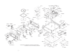
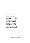
Wall Mount type HDD model
MPC-WA1HA
User’s Manual
CONTEC CO.,LTD.
Check Your Package
Thank you for purchasing the CONTEC product.
The product consists of the items listed below.
Check, with the following list, that your package is complete. If you discover damaged or missing items,
contact your retailer.
Keep the motherboard product case with care as it is required if the motherboard is repaired or replaced.
Product Configuration List
- MPC-WA1HA…1
- This User’s Manual …1
- Key…2
- The attachment fitting…2
- The chassis fastening brackets (2type) …2
- Fixed clamp…1
- Power cable retaining bracket…1
- Three-point sems screw (M3 x 6) …10
- Three-point sems screw (M4 x 8) …8
- Flat-head screws (M3 x 5) …2
- Power supply cable (125VAC 2.5m) …1
- LAN cable (cross 30cm category 5) …1
- Slot cover…6
- Serial port (9 pin D-SUB male) ribbon cable (With a bracket for attachment) …1
- PC-RAS(PCI) User’s Manual…1
- PC-RAS(PCI) software library (FD) …1
- Motherboard Quick Reference…1
- Motherboard product case & static-shielding bag…1
- IDE40 pin ribbon cable…1
- Floppy ribbon cable…1
- Driver utility (CD-ROM) …1
- Motherboard layout seal…1
- Other motherboard documents…1 set
- Processor User’s Manual…1
MPC-WA1HA
i
User's Manual
User's Manual
MPC-WA1HA
Floppy ribbon cable
CD-ROM
Fixed clamp
Key
Serial port
ribbon cable
FD
The attachment
fitting
×6
Flat-head screws
(M3 × 5) × 2
Slot cover
(M3 × 6) × 10
(M4 × 8) × 8
IDE40 pin
ribbon cable
Power cable
retaining bracket
Three-point sems screw
The Chassis fastening
brackets (2type)
Power supply cable
LAN cable
M/B
Quick
Reference
PC-RAS(PCI)
User's Manual
Motherboard
Quick
Reference
PC-RAS(PCI)
User's Manual
Other motherboard
documents
Other motherboard
documents
Processor
User's Manual
Motherboard
layout seal
Processor
User's Manual
Motherboard product case
& static-shielding bag
Copyright
Copyright 2003 CONTEC CO., LTD. ALL RIGHTS RESERVED
No part of this document may be copied or reproduced in any form by any means without prior written
consent of CONTEC CO., LTD.
CONTEC CO., LTD. makes no commitment to update or keep current the information contained in this
document. The information in this document is subject to change without notice.
All relevant issues have been considered in the preparation of this document. Should you notice an
omission or any questionable item in this document, please feel free to notify CONTEC CO., LTD.
Regardless of the foregoing statement, CONTEC assumes no responsibility for any errors that may
appear in this document or for results obtained by the user as a result of using this product.
Trademarks
MS, Microsoft, Windows, Windows NT and MS-DOS are trademarks of Microsoft Corporation. Intel
and Pentium are a registered trademark of Intel Corporation. Other brand and product names are
trademarks of their respective holder.
ii
MPC-WA1HA
Table of Contents
Check Your Package.................................................................................................................................... i
Copyright ..................................................................................................................................................... ii
Trademarks .................................................................................................................................................. ii
1.
BEFORE USING THE PRODUCT
1
About MPC-WA1HA ................................................................................................................................. 1
Features................................................................................................................................................. 1
Customer Support ....................................................................................................................................... 2
Web Site................................................................................................................................................ 2
Limited One-Year Warranty............................................................................................................... 2
How to Obtain Service........................................................................................................................ 2
Liability................................................................................................................................................. 2
Safety Precautions....................................................................................................................................... 3
Safety Information............................................................................................................................... 3
Handling Precautions .......................................................................................................................... 4
Special Note ......................................................................................................................................... 5
Environment ......................................................................................................................................... 6
Inspection ............................................................................................................................................. 6
Storage .................................................................................................................................................. 6
2.
OVERVIEW
9
Specification ................................................................................................................................................ 9
Layout Drawing......................................................................................................................................... 11
External Dimensions................................................................................................................................. 12
3.
HARDWARE SETUP
13
Opening and closing the chassis ...................................................................................................... 13
Drawing out the chassis .................................................................................................................... 15
Securing the power cable.................................................................................................................. 16
Removing the faceplate..................................................................................................................... 18
Removing the filter............................................................................................................................ 18
Securing the board............................................................................................................................. 19
Removing the 3.5-inch bracket ........................................................................................................ 20
Removing the 5-inch bracket ........................................................................................................... 21
Securing the chassis........................................................................................................................... 22
Connections........................................................................................................................................ 23
Setting ................................................................................................................................................. 26
Installation condition......................................................................................................................... 27
MPC-WA1HA
iii
4.
EACH FUNCTION
29
POWER SW....................................................................................................................................... 29
RESET SW......................................................................................................................................... 29
Motherboard connectors ................................................................................................................... 29
RAS board.......................................................................................................................................... 29
iv
MPC-WA1HA
1. Before Using the Product
1. Before Using the Product
This chapter provides information you should know before using the product.
About MPC-WA1HA
The MPC-WA1HA is an IBM PC/AT compatible, general-purpose computer with an Intel Pentium 4
4.2B GHz processor.
The MPC-WA1HA includes a CONTEC RAS board as a standard component, capable of operation
monitoring (temperatures, voltages, fans), remote control and monitoring through a web browser,
watchdog timer operation, and general-purpose input/output.
The MPC-WA1HA uses a full front-maintenance type of chassis for easier maintenance.
Please read this manual carefully before connecting to the external device or performing system
configuration.
Features
-
Genuine Intel motherboard used
-
Standard with a Pentium 4 2.4B GHz (533-MHz FSB) as the CPU
-
Standard with 256 MB of DDR SDRAM (DDR333 PC2700)
-
Ultra ATA/100 40GB is plugged in HDD.
-
Front maintenance structure allowing the PC to receive maintenance while remaining installed
-
Standard with the CONTEC RAS board PC-RAS(PCI) that enables remote control through a web
browser
-
Standard with wall mount brackets dedicated to built-in use
-
The chassis frame is made of hard-to-rust, strong stainless steel (SUS304).
MPC-WA1HA
1
1. Before Using the Product
Customer Support
CONTEC provides the following support services for you to use CONTEC products more efficiently and
comfortably.
Web Site
Japanese
English
Chinese
http://www.contec.co.jp/
http://www.contec.com/
http://www.contec.com.cn/
Latest product information
CONTEC provides up-to-date information on products.
CONTEC also provides product manuals and various technical documents in the PDF.
Free download
You can download updated driver software and differential files as well as sample programs available in
several languages.
Note! For product information
Contact your retailer if you have any technical question about a CONTEC product or need its price,
delivery time, or estimate information.
Limited One-Year Warranty
CONTEC Products are warranted by CONTEC CO., LTD. to be free from defects in material and
workmanship for up to one year from the date of purchase by the original purchaser.
Repair will be free of charge only when this device is returned freight prepaid with a copy of the original
invoice and a Return Merchandise Authorization to the distributor or the CONTEC group office, from
which it was purchased.
This warranty is not applicable for scratches or normal wear, but only for the electronic circuitry and
original products. The warranty is not applicable if the device has been tampered with or damaged
through abuse, mistreatment, neglect, or unreasonable use, or if the original invoice is not included, in
which case repairs will be considered beyond the warranty policy.
How to Obtain Service
For replacement or repair, return the device freight prepaid, with a copy of the original invoice. Please
obtain a Return Merchandise Authorization Number (RMA) from the CONTEC group office where you
purchased before returning any product.
*
No product will be accepted by CONTEC group without the RMA number.
Liability
The obligation of the warrantor is solely to repair or replace the product. In no event will the warrantor
be liable for any incidental or consequential damages due to such defect or consequences that arise from
inexperienced usage, misuse, or malfunction of this device.
2
MPC-WA1HA
1. Before Using the Product
Safety Precautions
Understand the following definitions and precautions to use the product safely.
Safety Information
This document provides safety information using the following symbols to prevent accidents resulting in
injury or death and the destruction of equipment and resources. Understand the meanings of these labels
to operate the equipment safely.
DANGER
DANGER indicates an imminently hazardous situation which, if not avoided, will
result in death or serious injury.
WARNING
WARNING indicates a potentially hazardous situation which, if not avoided, could
result in death or serious injury.
CAUTION
CAUTION indicates a potentially hazardous situation which, if not avoided, may
result in minor or moderate injury or in property damage.
MPC-WA1HA
3
1. Before Using the Product
Handling Precautions
CAUTION
-
Do not use or store the equipment in a hot or cold place, or in a place that is subject to severe
temperature changes.
Example
- The place that is subject to direct sunlight.
- The place that is near the hot place.
-
Do not use or store the equipment in a highly humid or dusty place. It is very dangerous to use the
equipment with water, liquid, or conductive dust left inside. If the equipment must be used in such
an unfavorable environment, install it in a dusttight structure such as a dust-proof control panel.
-
Do not use or store in environments subject to shock or vibration.
-
Do not use or store the product near equipment generating a strong magnetic field or sounds.
-
Do not use or store the product in the air that chemicals are giving off or the place that is near the
chemicals.
-
Clean the MPC-WA1HA by wiping lightly with a soft cloth moistened with water or a cleaning
solution. Take care to avoid the use of benzene, thinners or other volatile solutions which may
cause deformation or discoloration.
-
Be sure to unplug the power cable from the wall outlet before mounting or demounting an expansion
board or before connecting or disconnecting a cable to/from any connector.
-
Do not modify the MPC-WA1HA. CONTEC will bear no responsibility for any problems, etc.,
resulting from modifying this product.
-
If you find any fault or abnormal symptom (such as an unusual smell or overheat), unplug the power
cable first and consult your local retailer.
-
Use a power cable to be used must conform to the rated supply voltage and wall outlet to be used.
(The attached cable is for 125 VAC.)
-
About the life expectancy of components.
(1) Power supply : The lifespan is 30,000 hours for continuous operation at 40 degrees centigrade.
Note, however, that it is shortened depending on the operating temperature
(affected by high temperatures).
(2) FAN :
The lifespan of the chassis fan is 50,000 hours for continuous operation at 25
degrees centigrade. Note, however, that it is shortened depending on the
operating temperature (affected by high temperatures).
For the processor fan, refer to the processor manual.
(3) Motherboard:
The lifespan of the motherboard is eight years for continuous operation at 25
degrees centigrade. Note, however, that it is shortened depending on the
operating temperature (affected by high temperatures).
(4) Battery:
For the battery on the motherboard, refer to the motherboard manual.
For the battery on the RAS board, refer to the PC-RAS(PCI) manual.
* CONTEC accepts your request for replacing each consumable in the MPC-WA1HA as a
request for repair (at an additional cost).
-
4
For connection to peripheral devices, use grounded shielded cables.
MPC-WA1HA
1. Before Using the Product
Special Note
Specifications
The MPC-WA1HA consists of individually commercial products. For details on the specifications of
each of these components, refer to the corresponding manual or web site.
Intel Corporation HP : http://support.intel.com
Operation guarantee
Although CONTEC has checked the equipment for connectivity, the customer should evaluate it
sufficiently as well before adopting the equipment.
Support
Questions and inquiries about individual components are also supported by their respective
manufacturers.
-
Motherboard [BOXD845GEBV2L] and processor [BX80532PE2400D]
Maker
: Intel Corporation
Support site on the Web: http://support.intel.com
-
For general information on the equipment or other components, contact the CONTEC general
information center.
CONTEC may not be able to answer questions or inquiries about hardware or software installed by
the customer or about the entire system.
Initial defect
If any component develops an initial defect during normal operation within the guarantee period, it is
handled by the manufacturer of the component. Contact your local retailer, and CONTEC will request
the manufacturer to take appropriate action.
Fault and repair
If any component causes a fault that requires repair, it is handled by the manufacturer of the component.
Please note in advance that some manufacturers may not be able to analyze individual faults and to make
answers in writing .
If a component causes a fault, contact your local retailer, and CONTEC will request the manufacturer to
take appropriate action.
MPC-WA1HA
5
1. Before Using the Product
Environment
Use this product in the following environment. If used in an unauthorized environment, the chassis may
overheat, malfunction, or cause a failure.
Operating temperature
5 to 35°C
Humidity
20 to 80%RH (No condensation)
Corrosive gases
None
Floating dust particles
Not to be excessive
Inspection
Inspect the product periodically as follows to use it safely.
The ventilation slits are not covered, and neither dust nor alien substance
is attached to the ventilation slits.
The connector has no stain or corrosion.
Storage
When storing this product, keep it in its original packing form.
(1) Wrap it in the packing material, then put it in the box.
(2) Store the package at room temperature at a place free from direct sunlight, moisture, shock,
vibration, magnetism, and static electricity.
6
MPC-WA1HA
1. Before Using the Product
FCC PART 15 Class A Notice
NOTE
This equipment has been tested and found to comply with the limits for a Class A digital device,
pursuant to part 15 of the FCC Rules. These limits are designed to provide reasonable protection
against harmful interference when the equipment is operated in commercial environment.
This equipment generates, uses, and can radiate radio frequency energy and, if not installed and
used in accordance with the instruction manual, may cause harmful interference to radio
communications. Operation of this equipment in a residential area is likely to cause harmful
interference at his own expense.
W ARNING TO USER
Change or modifications not expressly approved the manufacturer can void the user's authority to
operate this equipment.
MPC-WA1HA
7
1. Before Using the Product
8
MPC-WA1HA
2. Overview
2. Overview
Specification
Table 2.1. Functional Specifications <1/2>
Item
Motherboard
CPU
Specifications
D845GEBV2L (Intel) *1
Pentium 4 2.4BGHz FSB 533MHz(Intel)
L2 Cache : 512KB
Memory
256 MB standard DDR SDRAM(DDR333 PC2700) 256MB x 1(non ECC)
2GB(Max.) (184 pin DDR SDRAM Socket x 2)
DDR333/266 non ECC(ECC memory works even in non-ECC monde.)
Chip set
Intel 845GE
Video
Intel 82845GE (Integrated in the 845GE chipset)
Display I/F
Analog RGB MINI D-SUB15 pin
Audio
AC97 compliant line input, line output, microphone input
FDD I/F
3.5 inch FDD (2 mode) *2
IDE HDD I/F
Primary : 3.5 inch HDD 40GB Ultra ATA/100
Secondary : 5-inch CD-ROM (24x speed) *2
Serial I/F
Max. 115,200bps 9 pin D-SUB
Parallel I/F
25 pin D-SUB
LAN I/F
Intel 82562ET 10BASE-T/100BASE-TX RJ-45 connector
USB I/F
USB2.0 front 4 port, on-board 2 port
Keyboard I/F
PS/2 type keyboard (6 pin MINI DIN connector)
Mouse I/F
PS/2 type mouse (6 pin MINI DIN connector)
Real time clock
Accuracy : ±2 minutes/month(25°C)
Expansion slot
AGP: 1 slot 4X/2X 1.5V
PCI: 5 slots
Power supply
capacity
Total capacity for AGP x 1, PCI x 5, and USB x 6 *3
+5V : 6.0A +12V : 1.0A +3.3V : 3.0A
-12V : 0.4A (only PCI slot)
+1.5V : 0.5A (only AGP slot)
Attach-able board
Dimension (mm)
Length (L) : 200(Max.) SLOT0 and SLOT3~SLOT6
130(Max.) SLOT2
(Assuming that the PC-RAS(PCI) is plugged in SLOT1)
High (H) : 87(Min.)to122(Max.) *4
RAS functions
PC-RAS(PCI) (CONTEC) *5
Monitor functions
Temperature, DC voltage, and fan
Web functions
Setting, monitoring, and remote power control
WDT
Monitor interval: 500µsec to 10min
General-purpose I/O
Four channels of each I/O
Miscellaneous
Log function
Chassis
Wall-Mount TYPE (CONTEC)
FAN
Front fan (intake) x 2; Rear fan (exhaust) x 1 *6
SW, LED
POWER-ON SW, RESET SW, POWER LED, HDD LED
MPC-WA1HA
9
2. Overview
Table 2.1. Functional Specifications <2/2>
Item
Support OS *7
Specifications
PC-RAS(PCI) Utility soft supported OS *8
Windows XP, Windows 2000
OSs verified by CONTEC *9
Windows XP Professional
Windows 2000 Professional
Input supply voltage
90 to 264VAC(47 to 63Hz) Continuous input
Current consumption
450VA(Max.) *10
External dimensions (mm)
396(W) x 180(H) x 287(D) (Does not contain the attachment fitting)
Weight
Approx.12.9kg
*1 For detailed specifications of the motherboard, refer to the motherboard manual.
View the manual on the bundled CD-ROM (prepared by Intel) or the one downloaded from the Intel’s web site.
*2 Integral 5-inch type made up of a 5-inch low-profile CD-ROM (24x speed) drive and a 3.5-inch low-profile FDD
(two-mode type).
Neither a 5-inch nor 3.5-inch drive can be added.
*3 In standby mode, power (+5 VSB) cannot be supplied from the USB or PS/2 connector.
+3.3VSB of the PCI slot cannot be supplied.
*4 The minimum height limit is the minimum dimension at which a board can be fixed by the board stopper.
Low-profile boards cannot be fixed by the board stopper.
*5 Refer to the manual for the PC-RAS(PCI) for its detailed specifications.
*6 Power to the chassis and CPU fans is supplied from the PC-RAS(PCI).
Fan connectors on the motherboard are not available.
*7 Obtain the motherboard driver copied from the bundled CD-ROM (prepared by Intel) or downloaded from the
Intel’s web site.
*8 Use the PC-RAS(PCI) utility software found in the bundled FD (prepared by CONTEC).
*9 It has been verified that the MPC-WA1HA allows either OS to be installed from the CD-ROM drive.
*10 When the expansion slots are being used
10
MPC-WA1HA
2. Overview
Table 2.2. Installation Environment Requirements
Parameter
Power supply
specifications
Requirement description
Allowable instantaneous
Less than 10ms
power outage
1.8 kVAC (input-FG) One minute
Dielectric strength
50MΩ (500VDC)
Operating temperature
0 to 35°C
Storage temperature
-10 to 60°C
Humidity
20 to 80%RH(No condensation)
Floating dust particles
Not to be excessive
Corrosive gases
None
Line-noise
Line noise
resistance
AC line/2kV, Signal line/1kV
(IEC1000-4-4Level3, EN61000-4-4Level3)
Static
Contact discharge/4kV
voltage
resistance
Atmospheric discharge/8kV
(IEC1000-4-2Level2, EN61000-4-2Level2)
(IEC1000-4-2Level3, EN61000-4-2Level3)
Ambient
specifications
Vibration
resistance *1
Anti shock *1
When the
HDD is in
use.
10 to 57Hz/semi-amplitude 0.015mm 57 to 150Hz: 1.96m/s2
When the
HDD is
not in
use.
10 to 57Hz/semi-amplitude 0.035mm 57 to 150Hz: 4.9m/s2
40 min. each in x, y, and z directions
When the
98m/s2 , half-sine shock for 11 ms in x, y, and z directions
HDD is in
use, and
(JIS C0041-compliant, IEC68-2-27-compliant)
40 min. each in x, y, and z directions
(JIS C0040-compliant, IEC68-2-6-compliant)
(JIS C0040-compliant, IEC68-2-6-compliant)
is not in
use
Grounding
Class D grounding (previous class 3 grounding)
*1 When the FDD and CD-ROM are not in use.
Layout Drawing
POWER-ON SW
PC-RAS(PCI)
POWER LED (Green) For details, refer to the PC-RAS(PCI) manual.
HDD LED (Red)
RESET SW
Main power switch
SLOT0 SLOT2 SLOT4 SLOT6
SLOT1 SLOT3 SLOT5
Motherboard connectors
For details, refer to the motherboard manual.
Figure 2.1 Layout Drawing
MPC-WA1HA
11
2. Overview
External Dimensions
287
When closed
R6
20
2R3
6
30
60
180
2-φ6
80
444
424
396
[mm]
Figure 2.2 External Dimensions (When closed)
When opened
180
(450)
(160)
(537)
(537)
180
444
396
252
[mm]
Figure 2.3 External Dimensions (When opened)
12
MPC-WA1HA
3. Hardware Setup
3. Hardware Setup
Before setting up the hardware of the MPC-WA1HA, always make sure that the power supply is off.
Opening and closing the chassis
Opening procedure
Take the following steps to open the chassis.
1. Use the attached key to unlock the chassis (as (1) in the sketch shown below).
2.
Pull the left and right handles toward you (as (3) in the sketch) while holding down their latches ((2)
in the sketch).
(2)
(3)
(2)
(1)
Figure3.1 Unlocking the chassis
3.
Remove a pair of left and right screws ((4) in the sketch shown below).
(4)
(4)
Figure 3.2 Removing the screws
MPC-WA1HA
13
3. Hardware Setup
4.
Open the chassis upward (as (5) in the sketch shown below).
(5)
Figure 3.3 Opening procedure
Closing the chassis
1.
Close the top lid of the chassis while pulling the lever shown in the sketch below.
Pull the level out.
Figure 3.4 Closing the chassis
2.
14
Take the steps to open the chassis in reverse order to retract and lock the chassis.
MPC-WA1HA
3. Hardware Setup
Drawing out the chassis
1.
Draw the chassis toward you from the housing, then pull it out (as (2) in the upper sketch below)
while holding down the black levers ((1) in the sketch) on both sides.
(1)
(1)
(2)
Figure 3.5 Drawing out the chassis
2.
To draw the chassis into the housing, take the steps to draw it out in reverse order to put it back in
place.
CAUTION
When drawing the chassis from or into the wall-mounted housing (fastened onto the wall), place a
table below the housing in advance not to let the chassis fall accidentally.
MPC-WA1HA
15
3. Hardware Setup
Securing the power cable
Removing the power cable retaining bracket fixing screw
Remove the screw ((1) in the following sketch) below the main power switch so that the power cable
retaining bracket can be attached.
(1)
Figure 3.6 Removing the screws
Attaching the power cable retaining bracket and fixed clamp
Insert the fixed clamp into the power cable retaining bracket as (2) in the sketch below. Then, use the
screw removed above and the supplied screw (M3 x 6) to fasten the power cable retaining bracket.
Attach the retaining bracket with its large notch up (for exhaust of the power supply’s fan).
Use the power cable retaining bracket, fixed clamp, and screw (M3 x 6) supplied as accessories for the
MPC-WA1HA.
(2)
Power cable
retaining bracket
Fixed clamp
Figure 3.7 Fastening the power cable retaining bracket
16
MPC-WA1HA
3. Hardware Setup
Plugging the power cable
Plug the power cable deep into the inlet (as (3) in the following sketch).
(3)
Figure 3.8 Plugging the power cable
Securing the power cable
Pass the power cable through the fixed clamp and lock the clamp.
Slide the locked clamp toward the power cable plug ((4) in the following sketch) to secure the power
cable.
(4)
Lock the clamp.
Figure 3.9. Securing the power cable
MPC-WA1HA
17
3. Hardware Setup
Removing the faceplate
Remove three screws from the front panel to remove the faceplate as shown below.
Board
Cover
Remove the screws
Figure 3.10 Removing the faceplate
Removing the filter
Remove the filter as shown below.
Figure 3.11 Removing the filter
CAUTION
Clean the filter periodically.
Using the MPC-WA1HA with the filter left dirty increases the interior temperature of the chassis,
resulting in unexpected trouble.
18
MPC-WA1HA
3. Hardware Setup
Securing the board
Mounting the board
Plug the board into a slot and secure it using a supplied screw (M3 x 6).
Attach supplied slot covers to the slots with no board inserted.
(1)
Figure 3.12 Mounting the board
CAUTION
Make sure that the board has been mounted securely.
Securing the board
Loosen the screw ((2) in the following sketch) in the board fastening clamp first as shown below.
(2)
Figure 3.13 Securing the board (1/2)
MPC-WA1HA
19
3. Hardware Setup
Slide the loosened screw to fasten the board with the fastening clamp, then tighten up the screw (as (3) in
the following sketch).
(3)
Slide
Fasten with clamp
Figure 3.13 Securing the board (2/2)
Removing the 3.5-inch bracket
As shown below, remove two screws and remove the 3.5-inch bracket by sliding it upward.
Slide upward.
Remove the screws.
Figure 3.14 Removing the 3.5-inch bracket
20
MPC-WA1HA
3. Hardware Setup
Removing the 5-inch bracket
As shown below, remove four screws and remove the 5-inch bracket by sliding it downward.
Remove the screws.
Slide downward.
Figure 3.15 Removing the 5-inch bracket
MPC-WA1HA
21
3. Hardware Setup
Securing the chassis
When wall-mounting the MPC-WA1HA on a panel, secure the main body as instructed below.
Attaching the chassis fastening brackets
Draw the chassis from the mousing, then attach one chassis fastening bracket to the chassis using flathead screws (M3 x 5). To the housing, attach the other chassis fastening bracket using screws (M3 x 6).
The two chassis fastening brackets are different in type. Attach the right ones at the right positions in the
right orientations.
Use the chassis fastening brackets, flat-head screws, and screws (M3 x 6) supplied as accessories for the
MPC-WA1HA.
Chassis
(Main body)
Flad-head screws
(M3 x 5)
Chassis fastening brackets
Housing
Three-point sems screw
(M3 x 6)
Figure 3.16 Attaching the chassis fastening brackets
Securing the chassis
Secure the chassis enclosed in the housing by tightening the screw (M3 x 6) on the chassis fastening
bracket on the front face.
Three-point sems screw
(M3 x 6)
Figure 3.17 Securing the chassis
22
MPC-WA1HA
3. Hardware Setup
Connections
Internal connections
Leave the internal connections untouched as possible because their wiring is complicated.
If you disconnect a wire or cable, jot down its connection in advance so that you can restore it later.
POWER
RESET
CD/FDD
HDD
P/S
RAS
Figure 3.18 Internal connections (image)
MPC-WA1HA
23
3. Hardware Setup
CD/FDD
HDD
P/S
M/B
RAS
Figure 3.19 Internal connections (block diagram)
When connecting internal components, refer to the internal connection diagram and use the following
procedure.
1.
Connecting DC power cables to the RAS board and to the motherboard
-
Connect the power distribution cable to the ATX20P connection, of all the DC power cables from
the power supply (abbreviated P/S). Connect the 20P connector of the connected power distribution
cable to the PS connector on the motherboard (abbreviated M/B). Connect the 4P connector of the
power distribution cable to the CN9 connector on the PC-RAS(PCI) (abbreviated RAS) board. Note
that the 4P connector has the same shape as the peripheral 4P connector (large) of the DC power
cable from the P/S. Be careful not to make a mistake to connect the peripheral 4P connector (large)
of the DC power cable to the CN9 connector on the RAS board. Note also that the 4P connector of
the power distribution cable is dedicated to the RAS board and must not be connected to any
peripheral device. The peripheral device will not work correctly if the 4P connector is connected to
it by mistake.
-
Connect the ATX12V4P connector of a DC power cable to the 12V connector (near the processor)
on the M/B.
2.
Connecting DC power cables to peripheral devices
-
Connect the peripheral 4P connectors (large) from the P/S to the power connectors on the FDD and
CD-ROM drive.
24
MPC-WA1HA
3. Hardware Setup
-
Connect the peripheral 4P connector (large) from the P/S to the 3.5-inch HDD power connector.
You can neither add any peripheral device (such as an HDD) or use a peripheral-dedicated DC
power cable (4P large or small) for any device other than the predetermined peripheral.
3.
Connecting signal cables to the FDD and CD-ROM drive
-
Connect the FDD connector on the M/B to the FDD’s 34P connector using the round FDD cable
(34P).
-
Connect the SEC IDE connector on the M/B to the CD-ROM drive’s 40P connector using the round
IDE cable (40P).
4.
Connecting the HDD signal cable
-
Connect the PRI IDE connector on the M/B to the HDD’s 40P connector using the IDE ribbon cable
(80-conductor type supporting ATA 100/60).
5.
Connecting the fan cables
-
Connect the processor fan cable to the CN10 on the RAS board.
-
Connect the cable for the chassis rear fan (80-mm squared exhaust fan) to the CN11 connector on the
RAS board.
-
Connect the cable for the chassis front left fan (60-mm squared intake fan) to the CN4 connector on
the RAS board.
-
Connect the cable for the chassis front right fan (60-mm squared intake fan) to the CN5 connector
on the RAS board.
For connection to the fan connectors on the RAS board, use the specified fan cables. If you make a
wrong fan connection, the RAS board cannot perform fan monitoring normally.
The fan connector on the M/B cannot be used. Do not connect any fan cable to it.
6.
Connecting the chassis SW and LED cables
-
Connect the chassis POWER SW cable (labeled POWER at the connector) to the JP4 (2P) connector
on the RAS board. The RAS board connector is nonpolarized.
-
Connect the chassis RESET SW cable (labeled RESET at the connector) to the JP5 (2P) connector
on the RAS board. The RAS board connector is nonpolarized.
-
Connect the green and black chassis POWER LED cables (a pair of cables provided with one
connector each) to pins 2 and 4 of the FRONT PANEL HDR on the M/B, respectively.
-
Connect the red and black chassis HDD LED cables (labeled H.D.D LED at the connectors) to pins
1 and 3 of the FRONT PANEL HDR on the M/B, respectively.
-
Connect the JP6 (2P) connector on the RAS board to pins 6 and 8 of the FRONT PANEL HDR on
the M/B using the POWER cable (black and white, two-conductor cable labeled POWER at the
connector). The connector is nonpolarized.
-
Connect the JP7 (2P) connector on the RAS board to pins 5 and 7 of the FRONT PANEL HDR on
the M/B using the RESET cable (black and yellow, two-conductor cable labeled RESET at the
connector). The connector is nonpolarized.
For details on each connector, refer to the relevant manual.
MPC-WA1HA
25
3. Hardware Setup
Connecting the LAN cable
For connecting the LAN interface on the motherboard, the RAS board PC-RAS(PCI) provides a hub
through which to connect the MPC-WA1HA to the host. Connect the LAN connector on the
motherboard to one of the two LAN connectors on the PC-RAS(PCI) board (either will do) using the
supplied LAN cable (30-cm cross cable in category 5). Connect the other LAN connector on the RAS
board to the host using either a straight or cross cable. The LAN connection cable (category 5) needs to
be prepared by the customer. Refer to the PC-RAS(PCI) manual for details.
Connecting the serial cable
A mounting bracket with two serial port (male DB-9 connector) ribbon cables connected is supplied as
an accessory. It is used for the RAS board PC-RAS(PCI) to use an external UPS. Refer to the
PC-RAS(PCI) manual for how to attach and use that accessory.
Setting
Factory settings of the motherboard BOXD845GEBV2L
The motherboard is shipped with the initial values untouched.
For details, see the BOXD845GEBV2L manual.
RAS board [PC-RAS(PCI)] factory setting
Table 3.1 PC-RAS(PCI) factory setting
Factory setting
No.
SW1
Function
0
SW2 1
OFF
2
3
OFF
OFF
4
5
OFF
OFF
6
7
OFF
OFF
8
OFF
For details, refer to PC-RAS(PCI) manual.
5 inch CD-ROM factory setting
Table 3.2 5 inch CD-ROM factory setting
Factory setting
No.
J4
SHORT
J5
OPEN
J6
OPEN
Function
SHORT: Master
Use the CD-ROM drive as the master device left as factory-set.
26
MPC-WA1HA
3. Hardware Setup
Installation condition
To use the MPC-WA1HA at an ambient temperature within the range of acceptable installation
environment conditions, allow a clearance of at least 10 mm above the chassis and a clearance of at least
50 mm beside and below.
Install the chassis only horizontally (at a vertical or horizontal slant angle within 5 degrees). It cannot be
installed vertically.
Side
160
180
10
270
620
50
(537)
[mm]
620
Top
50
396
50
[mm]
Figure 3.20 Clearances around the chassis
MPC-WA1HA
27
3. Hardware Setup
28
MPC-WA1HA
4. Each Function
4. Each Function
POWER SW
To supply power to the MPC-WA1HA, turn on the main power switch, then press the POWER-ON SW.
RESET SW
The MPC-WA1HA has a hardware reset switch (RESET SW). As this switch is designed hard-to-press
to prevent itself from being pressed accidentally. Use a pointed object to press the switch.
Motherboard connectors
For the functions of motherboard connectors, refer to the motherboard manual.
RAS board
For the functions and use of the RAS board [PC-RAS(PCI)], refer to the PC-RAS(PCI) manual.
MPC-WA1HA
29
MPC-WA1HA
User’s Manual
CONTEC CO., LTD.
December 2003 Edition
3-9-31, Himesato, Nishiyodogawa-ku, Osaka 555-0025, Japan
Japanese http://www.contec.co.jp/
English http://www.contec.com/
Chinese http://www.contec.com.cn/
No part of this document may be copied or reproduced in any form by any means without prior written
consent of CONTEC CO., LTD.
[07042003]
[12262003]
Management No. A-46-843
Parts No.
LYDJ141