1
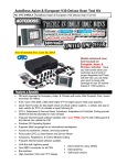
V30 Diagnostic Computer
USER MANUAL
Version 1.4
Copyright ©2008 by
Tech. Inc.
User Manual
Statement
Copyright © 2008 by AUTOBOSS TECH. INC. (short for "AUTOBOSS"). All rights reserved. No part of
this publication can be reproduced, stored in a retrieval system, or transmitted in any form or by any
means, electronic, mechanical, photocopying, recording or otherwise, without the prior written
permission of AUTOBOSS. The information contained herein is designed only for the use of this unit.
AUTOBOSS is not responsible for any use of this information as applied to other units.
Neither AUTOBOSS nor its affiliates shall be liable to the purchaser of this unit or third parties for
damages, losses, costs, or expenses incurred by purchaser or third parties as a result of: accident,
misuse, or abuse of this unit, or unauthorized modifications, repairs, or alterations to this unit, or
failure to strictly comply with AUTOBOSS operating and maintenance instructions.
AUTOBOSS shall not be liable for any damages or problems arising from the use of any options or
any consumable products other than those designated as Original AUTOBOSS Products or
AUTOBOSS Approved Products by AUTOBOSS.
General Notice: Other product names used herein are for identification purposes only and may be
trademarks of their respective owners. AUTOBOSS disclaims any and all rights in those marks.
The V-30 Diagnostic Computer can only operated by qualified technicians.
Trade mark
AUTOBOSS is a registered trademark of AUTOBOSS TECH. INC. (short for AUTOBOSS) in China
and other countries. All other AUTOBOSS trademarks, service marks, domain names, logos, and
company names referred to in this manual are either trademarks, registered trademarks, service
marks, domain names, logos, company names of or are otherwise the property of AUTOBOSS or its
affiliates. In countries where any of the AUTOBOSS trademarks, service marks, domain names, logos
and company names is not registered, AUTOBOSS claims other rights associated with unregistered
trademarks, service marks, domain names, logos, and company names. Other products or company
names referred in this manual may be trademarks of their respective owners. You may not use any
trademark, service mark, domain name, logo, or company name of AUTOBOSS or any third party
without permission from the owner of the applicable trademark, service mark, domain name, logo, or
company name.
You may contact AUTOBOSS by visiting AUTOBOSS at www.autoboss.net , or writing to AUTOBOSS,
5/F, East, Bldg.304, Shangbu Industrial Park, Zhenxing Rd., Futian, Shenzhen, China, to request
written permission to use Materials on this manual for purposes or for all other questions relating to
this manual.
-I-
User Manual
V30 User Manual instructions
Please read this user manual carefully before using the scanner.
The current user manual is based on the current features and functions available. Any new
added features and functions of V30 Diagnostic Computer will be added to the user manual in
the future. Updated versions of user manual will be available to download at AUTOBOSS
website (http://www.autoboss.net).
When reading the manual, please pay special attention to the words “Note”, “Caution” or
“Warning”, read them carefully for appropriate operation.
V30 Diagnostic Computer main unit maintenance:
Avoid shaking or dismantling as it may damage the internal components;
Do not use hard or sharp objects to touch the LCD screen; do not use excessive force; do not
expose the screen to strong sunlight for a long period;
Caution: keep it away from water, moisture, high temperature or very low temperature;
If necessary, calibrate the screen before testing to ensure the accuracy of LCD performance;
Keep the main unit away from strong magnetic fields.
Operation Instructions
For safe operation please follow the instructions below;
Keep the scanner away from heat or fumes when using it;
If the vehicle battery contains acid, Please keep your hands and skin or fire sources away from
the battery during testing;
Exhaust gas of vehicle contains harmful chemicals, please ensure adequate ventilation;
Do not touch the cooling system components or exhaust manifolds when engine is running ue to
the high temperatures reached;
Make sure the car is securely parked and the selector is at P or N position to prevent the vehicle
from moving when engine starts;
Make sure the (DLC) diagnostic link connector is ok before starting the test, otherwise the
scanner may be damaged. Autoboss suggests you test the Power/Earth with Multimeter first;
Do not switch off the power or unplug the connectors during testing, otherwise you may damage
the ECU or scanner.
- II -
User Manual
CONTENTS
1 Introduction .......................................................................................................................................1
1.1 FUNCTION AND FEATURE .................................................................................................... 1
1.2 LAYOUT OF MAIN UNIT ...................................................................................................... 1
1.3 TECHNICAL PARAMETERS................................................................................................... 2
1.4 CONFIGURATION ................................................................................................................. 2
2 Operation ..........................................................................................................................................8
2.1 POWER SUPPLY & CABLE CONNECTION ............................................................................. 8
2.1.1 Power Supply .............................................................................................................. 8
2.1.2 Cable Connection ....................................................................................................... 8
2.2 INTERFACE INSTRUCTION ................................................................................................... 9
2.2.1 Starting Interface ........................................................................................................ 9
2.2.2 Touch Screen Calibration ........................................................................................... 9
2.2.3 Diagnose Program.................................................................................................... 10
2.2.4 System Setting ............................................................................................................11
2.2.5 Self Test ..................................................................................................................... 13
2.2.6 PC LINK ................................................................................................................... 13
2.2.7 Version Information .................................................................................................. 13
2.3 SOFTWARE UPGRADING.................................................................................................... 15
2.3.1 Download and Install “V30 Update Client” ............................................................ 15
2.3.2 Check V30 S/N and Password................................................................................... 16
2.3.3 Upgrading Instructions............................................................................................. 17
2.4 TO PRINT SAVED FILES FROM SD CARD ............................................................... 21
3 Test Procedure ................................................................................................................................23
3.1 Engine ECU Testing Methods...................................................................................... 23
3.1.1 Testing Description ................................................................................................... 23
Order Information ...............................................................................................................................31
- III -
User Manual
1 Introduction
1.1 Function and Feature
OE level coverage for European, Asian,
American and Chinese cars
Supports Multi-language
Multiple-tasking
PC link available
CAN-BUS with high/low speed
One OBDII connector for all CAN bus
systems
Continuous software update online
High resolution TFT display
6-layer electronic circuit board
Self-check function
1.2 Layout of Main Unit
The main unit layout is as shown in left picture.
①
USB Port
②
COM Port
③
Diagnostic Port
④
Power Port
⑤
SD slot
⑥
Touch Pen slot
⑦
Touch Screen
⑧
Power Switch
-1-
User Manual
1.3 Technical Parameters
CPU: SAMSUNG ARM9 2410A, 200MHz;
Memory: 64M;
Flash card: SD card, 1G
Display: 5.6” VGA (640×480) ultra bright TFT;
Power supply: DC 8~12V, AC 110~250V 50Hz;
Port: Diagnosis port, COM port, USB port, Power Port;
Operating system: WINDOWS CE;
Storage temperature: -30~90ºC;
Working temperature: -10~80ºC;
Humidity: <90%.
1.4 Configuration
Picture
Item
Description
Name: V30 main unit
Function:
Quantity: 1
procedures and information
Name: SD card
Function:
Storage
of
Quantity:1
Diagnostic
programs
and
Display
testing
saved files
Name: Touch pen
Function: For touch screen
Quantity: 1
operation
-2-
User Manual
Picture
Item
Description
Name: Main Cable
Function: Connect the main
Quantity: 1
unit
&
connectors
for
diagnosis
Name: BENZ-38 connector
Function: Used for testing
Quantity: 1
Mercedes-Benz
equipped
with
vehicles
a
circular
38-pin DLC
Name: BMW-20 connector
Function: Used for testing
Quantity: 1
BMW vehicles equipped with
a 20-pin DLC
Name: Chery/Fiat -3 connector
Function: Used for testing
Quantity: 1
FIAT vehicles equipped with
a 3-pin DLC
Name: GM-12 connector
Function: Used for testing
Quantity: 1
GM/DAEWOO
vehicles
equipped with a 12-pin DLC
Name: Kia-20 connector
Function: Used for testing
Quantity: 1
KIA vehicles equipped with a
20-pin DLC
-3-
User Manual
Picture
Item
Description
Name: Mazda-17 connector
Function: Used for testing
Quantity: 1
MAZDA vehicles equipped
with a 17-pin DLC
Name: TOYOTA-17 connector
Function:
Used for testing
Quantity: 1
TOYOTA/LEXUS vehicles
equipped with a semi-circular
17pin DLC
Name: TOYOTA-22 connector
Function: Used for testing
Quantity: 1
Toyota and Lexus vehicles
with a rectangular 22-pin
DLC
Name: MIT-12+16 connector
Function: Used for testing
Quantity: 1
Mitsubishi and Hyundai
vehicles equipped with a
12-pin or 16-pin DLC
Name: HONDA-3 connector
Function: Used for testing
Quantity: 1
HONDA and ACURA
vehicles equipped with a
3-pin DLC
Name: BENZ-4 connector
Function: Used for testing
Quantity: 1
Mercedes-Benz vehicles
before 1997 with flash codes.
Those vehicles are usually
equipped with either a
rectangular 8-pin or 16-pin
-4-
User Manual
Picture
Item
Description
Name: AUDI-4 connector
Function: Used for testing
Quantity: 1
VW/AUDI vehicles with a
4-pin (2x2) DLC
Name: NISSAN-14 connector
Function: Used for testing
Quantity: 1
Nissan and Infiniti vehicles
equipped with a 14-pin DLC
Name: OBD-16 connector
Function: Used for testing
Quantity: 1
all vehicles compliant with
OBDII, EOBD and J1962
with the 16-pin DLC
Name: Jumper
Function: Short circuit test
Quantity: 1
for flash code reading
Name: Battery power cable
Function: Provide the
Quantity: 1
power supply via battery
Name: Cigarette lighter power
Function: Provide the power
cable
supply via cigarette lighter on
Quantity: 1
the car
-5-
User Manual
Picture
Item
Description
Name: Serial cable
Function: Connect the main
Quantity: 1
unit and PC base
Name: DC adaptor
Quantity: 1
Function: Provide 12V DC
voltage
Name: SD Card reader
Function: Read SD card for
Quantity: 1
software update or SD card
reading and writing
Fuse 5A 30*6
Spare parts
Fuse 5A 20*5
Spare parts
Name: main unit rubber bar
Function: To hold the plastic
Quantity: 1 pair
main unit margin
Note: Optional
Name: Benz-14 pin connector
Function:
Used
Quantity: 1
Mercedes-Benz Sprinter
Note: Optional
-6-
to
test
User Manual
Picture
Item
Description
Function:
Name: Chrysler-16 connector
Chrysler
Quantity: 1
protocol
Used
car
to
with
test
CCD
Note: Optional
NOTE: Configuration varies as per software package. For complete configuration, please refer
to the relevant shipping list.
-7-
User Manual
2 Operation
2.1 Power Supply & Cable Connection
2.1.1 Power Supply
There are 3 ways to get power for V30 Diagnostic
Computer. From:
①
Vehicle DLC, no external power supply
needed
②
Cigarette lighter
③
Battery
2.1.2 Cable Connection
How to get power supply:
1. Cigarette lighter plug
2. Battery cable
3. Battery
4. Main cable
5. Main cable adaptor
①
main unit if DLC is not self-powered.
②
8. Power port
9. Cigarette lighter
No external power supply needed if DLC is
self-powered.
③ NOTE: ALL 16 PIN DLC connectors have
12v supply and earth for scan tools.
6. Connector
7. Diagnosis port
Use Cigarette lighter or Battery cable to power
How cables are connected:
①
Check the type of DLC to see if external power
supply is required.
②
Select corresponding connectors for car make
and DLC.
③
Connect one end of main cable to the main
unit and the other end to the connector.
④
Plug the connector in to the DLC on car.
⑤
Turn on the unit using the power button to start
testing.
-8-
User Manual
2.2 Interface Instruction
2.2.1 Starting Interface
The interface shown on the left picture will appear
on the screen after the scanner is switched on.
2.2.2 Touch Screen Calibration
Several seconds after power is switched on, the
screen will go into calibration mode. Click
anywhere on the screen to start calibration if
necessary.
Note: Just wait for several seconds until the
diagnosis program runs if screen calibration is
not required.
Click on the center of cross with touch pen
according to the instruction on the screen. Repeat
the operation as the cross moves until the setting is
finished.
After the scanner is started, you will come to the
screen shown on the left picture which includes the
functions of [Diagnose], [Setting], [Self-check] and
[PC link], [Version]] and [Power off].
-9-
User Manual
2.2.3 Diagnose Program
After
entering
[Diagnose],you
will
enter
the
diagnostic interface where you can select the
region of vehicle manufacturer required: China,
Europe, Asia, America and Others(OBDⅡ/EOBD).
Europe: This section includes the diagnostic
programs for European vehicles.
Asia:
This
section
includes
the
diagnostic
programs for Asian and Korean vehicles.
America: This section includes the diagnostic
programs for US vehicles.
China:
This
section
includes
the
diagnostic
programs for Chinese vehicles.
Others: This diagnostic program can test all
vehicles with OBDⅡ/EOBD and CAN-OBD.
- 10 -
User Manual
2.2.4 System Setting
Click on the button [Setting] to enter settings for
language, time,download and unit.
2.2.4.1 Language Setting
V30 supports Multilanguage. Choose any language
needed under [working language] and press [OK]
to finish language setting.
2.2.4.2 Time Setting
Click on the button [Set time] to enter the menu for
time selection. By clicking on signs of “▼”or“▲”,
numbers will increase or decrease
correspondingly.
Click on the button [Set time] to finish the setting.
The dialog box ““Set system time
successfully!”” will popup.
Click [OK] to save the setting or [Cancel] to exit.
2.2.4.3 Download Communication Protocol
This function is for communication unit initialization.
When selected, a progress bar will be shown under
the version information of each diagnostic program
to indicate status of program download.
- 11 -
User Manual
2.2.4.4 Display Data Stream in British Unit
The data stream will be displayed in British unit
after [British unit] is chosen.
- 12 -
User Manual
2.2.5 Self Test
This is for hardware checking. Click on the button
[Self check] and any hardware faults will be
displayed. Please contact local distributor if a
hardware problem is reported.
If there are no hardware errors, the checking result
will be “System Self test report: No error
found.”
2.2.6 PC LINK
The control unit of V30 diagnostic computer can be
remotely operated via PC/Laptop by installing PC
LINK software.
Connect V30 main unit and PC with the COM cable
and run the PC LINK software on the PC, you will
be able to test vehicles from the PC interface as
shown on the left.
Note: Please contact the local distributor or
AUTOBOSS office for the PC LINK software
2.2.7 Version Information
Click on the button [About] to get the version
information of Hardware version, Software Serial
number, Release date, etc
Click [Back] to exit.
- 13 -
User Manual
2.2.8 Power Off
Click on [Exit] of main menu to switch off the V30
main unit. Warning dialog box “Do you want to
shutdown this device?” will popup. Click [No] to
return to the operating menu. Click [Yes] to switch
off the main unit.
- 14 -
User Manual
2.3 Software Upgrading
2.3.1 Download and Install “V30 Update
Client”
Step1: Visit AUTOBOSS website at
http://www.autoboss.net
Step2: Enter English website
Step3: Click on [V30] under the button
[Download] to enter download interface as
shown in left image.
Step4: Click on the option [V30 update client]
to download the update client to your PC.
A file named V30setupEn.exe will be saved to
your PC.
- 15 -
User Manual
Step 5: Double click on this file to install “V30
update client” step by step until you see the
image shown on the left.
Note: Just click on the button [Next] in each
step during the installation. We advise you
keep everything as default, but please
remember to input your name and company
name.
After finishing the installation, you will see the
icon shown below on your desktop.
V30Update Client.lnk
.
“V30 update client” is finished.
2.3.2 Check V30 S/N and Password
Check the S/N: Refer to 2.2.7 Version
information on page12 of this manual;
How to get password:
Click on the button [Activate] to get the original
register password as shown in left image.
- 16 -
User Manual
2.3.3 Upgrading Instructions
2.3.3.1 Run V30 update client program
Step1: Take out the SD card from main unit,
plug it into SD card reader and connect to PC.
Step 2: Double click to run the upgrading client
program on your PC and go to update interface
as shown in Fig 2-1.
Fig 2-1 update client starting interface
2.3.3.2 Login the Server
(1) Input the serial number and click on the
button [Connect to server] to enter the Fig
2-2 interface.
(2) Server. The default server is
‘www.autoboss.net’. Normally you do not
have to change the server.
(3) Input the password and click [OK].
Note:
Fig 2-2 login interface
① Be sure that both S/N and password are
correct. Please pay attention if the
letters are capitalized or not.
② If login takes a long time because of
low internet speed, you can exit and
retry;
③ Internet firewall might affect the
login. If login fails, please make
sure you have an internet
connection, and ensure any
installed firewall is not blocking the
connection to the server. For
detailed operation instructions,
please contact your local distributor.
- 17 -
User Manual
(4) After login succeeds, the diagnosis program
for the different manufacturers will be displayed
as shown in Fig2-3, please allow a short time for
the downloads to finish.
Fig2-3 Program list interface
2.3.3.3 Modify Password
After login succeeds, users can change the
original registered password.
Operation instruction:
Fig2-4
(1) Click on the button [Connect to server] in the
interface shown in Fig.2-3 to enter the interface
as shown in Fig.2-4.
(2) Click the button [Modify password] to enter
interface in Fig.2-5. After inputting the current
password and new password, click [OK]. You
will get a confirmation for successful
modification if the new password is OK.
Fig2-5 Modify password interface
Note: If you forget the password, please
contact Autoboss or your local dealer.
- 18 -
User Manual
2.3.3.4 Input Customer Information
You must fill in your personal information
when you first login to V30 update client;
otherwise you will not be able to download the
diagnose programs.
Operation instruction:
Click on the button [Customer info] after login
succeeds. You can see the interface as shown
in Fig2-6. Input your information to the relevant
spaces and click [OK] to save the information.
Fig2-6 Input customer info interface
2.3.3.5 Software Download
After user information is saved, you can
download the programs needed.
Operation instruction:
(1) Tick the small box before the relevant
program as shown in Fig.2-7;
Fig.2-7 Download interface
(2) Click on download button in right
column to enter download status.
Programs that are not downloaded
are highlighted in black. If download
succeeds they will be highlighted in
blue, failed downloads are highlighted
in red.
Note: A maximum of 10 items can
be chosen to download
simultaneously.
Fig.2-8 Download interface 2
(3) The programs will be downloaded to
your PC driver automatically.
- 19 -
User Manual
2.3.3.6 Update
(1) Take out the SD card from V30 main unit;
(2) Put the SD card into SD Card reader;
(3) Connect the Card-Reader to PC USB port;
(4) Select the SD card driver on the top-right
side of software installation interface as shown
in Fig.2-9;
Fig.2-9 Software installation interface
(5) Click on the button [Update], the selected
programs which have already been downloaded
to PC will be installed to SD card automatically.
Note: Make sure the update destination is
the SD card driver, to confirm enter “my
computer” on the PC to verify the drive letter
(ie E, F, I) assigned to the SD card
2.3.3.7 Software Management
You can delete old versions of software on the
SD card by Software management.
Operation instruction:
Click on the button [Management] to enter the
Fig.2-10 software installation interface
interface shown in Fig. 2-10. Select the software
not needed and click [Delete]. The selected
software will be uninstalled automatically.
2.3.3.8 Exit
After finishing all of the steps, click on [Exit] to
exit the update client.
- 20 -
User Manual
2.4 TO PRINT SAVED FILES FROM SD
CARD
(1). Insert SD card into supplied SD card reader
(2). Plug SD card reader into USB port of PC
(3). Window as shown will pop up, select “open
folder to view files” press “OK”
(4). If this window does not appear- go to “my
computer”, double click on the icon for
“Removable disc (F:)”
( NOTE: Drive letter
may vary depending on assignment of letters by
Windows.)
(5). Double click on “PRINT” folder and choose
file required, double click to open file.
- 21 -
User Manual
(6). Depending on which program your
PC has opened the file with, print using
printer icon or select “File” then “Print”
from top taskbar
- 22 -
User Manual
3 Test Procedure
3.1 Engine ECU Testing Methods
3.1.1 Testing Description
(1) Power up and turn on the scanner;
(2) Click on [Diagnose] --->[Europe] to enter
interface as shown on the left image;
(3)Select diagnostic program
Click on [VW], for example, to enter software
version selection interface shown in the left image.
Note: Program descriptions will be displayed
under the version information.
(4) Select a version such as V3.1 and click on [OK]
to download the diagnosis program as shown in left
image. Click on [Cancel] to go back to the previous
menu;
(4) Select vehicle type: take
Volkswagen/Audi for example, we have
two vehicle types for selection: [With
Canbus] and [Without Canbus]. Here
we choose without canbus car as an
example to introduce the test.
(5) NOTE: VEHICLES WITH CANBUS
WILL HAVE DLC PINS 6 AND 14
POPULATED
- 23 -
User Manual
(6) Select system:
[Common system Auto-Scan]: Test the
common-use ECU automatically;
[All system Auto-Scan]: Test all ECU
automatically;
[Common]: by choosing this item, all common-use
ECU will be displayed on the screen, users can
then select ECU required accordingly;
Other systems: Enter the systems as per relevant
ECU type.
(7) Click on [Common] To enter the interface
shown on the left.
Select [01-Engine] to enter the interface with the
following functions.
[01-Interrogate control unit versions]
[02-Interrogate fault memory]
[03-Final control diagnosis]
[04-Introduction of basis setting]
[05-Erase fault memory]
[06-End output]
[07-Coding]
[08-Read measuring value block]
[09-Read individual measuring value]
[10-Adaptation]
[11-Login procedure]
[15-Write VIN]
Note: Functions 04,07,10,15 require knowledge
of the systems operation, please use with care.
- 24 -
User Manual
①[01-Interrogate control unit versions]
Click on [01-Interrogate control unit versions] to
see the information of control unit as shown on the
left.
Note: Read out old ECU codes with this
function when performing ECU coding.
② [02-Interrogate fault memory]
To display the DTC saved in the current control unit,
click [02-Interrogate fault memory]. Please refer
to the left image.
③ [03-Final control diagnosis]
Click on the button [03-Final control diagnosis] to
test relevant actuator automatically as shown on
the left image. Click on [Active Test] to begin the
actuator test.
④ [04-Introduction of basis setting]
Click on the button [04-Introduction of basis
setting] for basic setting. Input desired text using
the number keys and click on the button [OK] to
start the basic setting.
[Del]: Delete the input numbers;
[Left]: Move cursor to left;
[Right]: Move cursor to right;
[Home]: Move cursor to Home;
[End: Move cursor to End;
[Enter]: confirm enters.
- 25 -
User Manual
The window of “Basic setting!” in left image will
popup after Basic Setting is done.
[Input]: continue to Input Channel number;
[Back]: Back to the Function Menu.
Note: Under basic setting mode, you can
perform solenoid and engine control unit
adaptation without starting the engine, or finish
λ control process self-adaptation when engine
starts. Also you can check faults or ignition
timing by connecting or disconnecting λ
control.
⑤ [05-Erase fault memory]
Click on the button [05-Erase fault memory] to
erase DTC as shown on the left image.
[OK]: Return to the previous menu
⑥ [06-End output]
To exit from the diagnostic program, please click on
[06-End output].
[Yes]: Exit the diagnosis program
[No]: Return to the previous menu
⑦ [07-Code control unit]
Click on [07-Code control unit] to go to interface
shown in left image. Then input the code and click
on [OK], the scanner will begin the coding. Click on
[OK] after coding succeeds.
Note: Please only code the ECU after the ECU
has been changed or a function has been
added (ie Cruise control) You can get the code
of the old ECU by choosing [01-Interrogate
control unit versions], then recode the new
ECU accordingly.
- 26 -
User Manual
⑧ [08-Read measuring value block]
Click on [08-Read measuring value block] to
enter interface shown in left image.
Please input
the relevant channel number, and click on [OK] to
read data stream information.
Note: For channel definition, please refer to
relevant technical manual.
The left image is the data stream of Group 01.
[PageUp]: See previous group data stream;
[PageDown]: See next group data stream;
[Waveform]: Review data stream in graph;
[Replay]: Review data stream;
[Channel]: Return to the interface to input
channel number;
[Back]: Return to the Function Menu.
[Print]: save the current screen to SD card.
⑨ [09-Read individual measuring value]
Click on [09-Read individual measuring value] to
enter the interface shown in the left image. Input
the channel number and click on [OK] to view the
relative data.
Click on [Read Value], and current value will be
displayed.
[Input]: Back to the input interface;
[Increase]: View the data of next channel
number.
[Decrease]: View the data of the previous
channel number;
[Read value]: Read current value;
[Back]: Back to function list menu;
[Print]: Save the current screen to SD card.
- 27 -
User Manual
⑩ [10-Adaptation]
]
Click on [10-Adaptation] to enter the interface of
inputting channel number as shown in left image.
Note: Self-adaptation includes: self-study
during idle, service reset, IMMO adaptation and
so on. You should login first for some of the
functions. For login methods, please refer to
[11-Login procedure] on page 26.
After inputting the relative channel number, click on
[OK] to enter the interface as shown in left image.
[Input]: Back to the “input channel number”
interface;
[Read]: Read the adaptation value of current
channel;
[Back]: Back to function list interface;
[Print]: Save the current screen to SD card.
Click on the button [Read] to read the adaptation
value of current channel.
[Input]: Input new adaptation value;
[Back]: Back to function list menu.
[Print]: Save the current screen to SD card.
Click on [Input] in enter the “input adaptation
value” interface shown on the left. Input the new
value and then click the button [Ok] to go to the
next step.
- 28 -
User Manual
After inputting the new value, new adaptation value
will be displayed on the screen. If no error is found,
please click on the button [Change] to go to the
next step.
Last step: Click on the button [Save] to save the
new adaptation value and go back to the
self-adaptation interface.
- 29 -
User Manual
[11-Login procedure]
To perform adaptation in some group, login will be
needed first. Just click on the button [11-Login
procedure], input the code number and then click
on [OK].
Note: Login is required when performing
functions such as ECU coding, change channel
adaptation and IMMO, etc.
[15-Write VIN]
rd
Volkswagen/Audi uses the 3 generation anti-theft
technology, if you change engine control unit and
instrument cluster at the same time you must
rewrite the VIN code. Please click on [15-Write VIN]
to input the new VIN.
[Del]: Delete the input numbers;
[Left]: Move cursor to left;
[Right]: Move cursor to right;
[Home]: Move cursor to Home;
[End: Move cursor to End;
[Enter]: confirm the information.
[Shift]:same with [Caps Lock] + [shift]
function on key board
- 30 -
User Manual
Order Information
AUTOBOSS TECH. INC.
Add: 5/F, Bldg. 304, Shangbu Industrial Park, Zhenxing Rd., Futian, Shenzhen 518028, P.R.China
Email: [email protected]
Tel: +86-755-8328 5146, 8328 5370
Fax: +86-755-82170248, 8328 5370
Website: http://www.autoboss.net
- 31 -