1
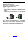
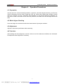
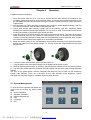
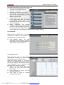
A-860 User manual
Announcement
Copyright © 2005 by AUTOBOSS TECH. INC. (short for "AUTOBOSS"). All rights reserved. No part
of this publication may be reproduced, stored in a retrieval system, or transmitted in any form or by
any means, electronic, mechanical, photocopying, recording or otherwise, without the prior written
permission of AUTOBOSS. The information contained herein is designed only for the use of this unit.
AUTOBOSS is not responsible for any use of this information as applied to other units.
Neither AUTOBOSS nor its affiliates shall be liable to the purchaser of this unit or third parties for
damages, losses, costs, or expenses incurred by purchaser or third parties as a result of: accident,
misuse, or abuse of this unit, or unauthorized modifications, repairs, or alterations to this unit, or
failure to strictly comply with AUTOBOSS operating and maintenance instructions.
AUTOBOSS shall not be liable for any damages or problems arising from the use of any options or
any consumable products other than those designated as Original AUTOBOSS Products or
AUTOBOSS Approved Products by AUTOBOSS.
General Notice: Other product names used herein are for identification purposes only and may be
trademarks of their respective owners. AUTOBOSS disclaims any and all rights in those marks.
The Wheel Aligner can only operated by the qualified technician.
Trade mark
AUTOBOSS is a registered trademark of AUTOBOSS TECH. INC. (short for AUTOBOSS) in China
and other countries. All other AUTOBOSS trademarks, service marks, domain names, logos, and
company names referred to in this manual are either trademarks, registered trademarks, service
marks, domain names, logos, company names of or are otherwise the property of AUTOBOSS or its
affiliates. In countries where any of the AUTOBOSS trademarks, service marks, domain names, logos
and company names is not registered, AUTOBOSS claims other rights associated with unregistered
trademarks, service marks, domain names, logos, and company names. Other products or company
names referred to in this manual may be trademarks of their respective owners. You may not use any
trademark, service mark, domain name, logo, or company name of AUTOBOSS or any third party
without permission from the owner of the applicable trademark, service mark, domain name, logo, or
company name. You may contact AUTOBOSS by visiting AUTOBOSS at www.autoboss.net , or
writing to AUTOBOSS, 5/F, East, Bldg.304, Shangbu Industrial Park, Zhenxing Rd., Futian,
Shenzhen, China , to request written permission to use Materials on this manual for purposes or for
all other questions relating to this manual.
i
PDF 文件使用 "pdfFactory Pro" 试用版本创建 www.fineprint.cn
A-860 User manual
Precautions
Precautions
l
l
l
l
l
l
l
l
l
l
l
l
l
l
Please read the User’s Manual carefully before operating.
Only the qualified technician can operate the Wheel Aligner.
The operator must have knowledge of computer application and basic theory of alignment.
The power voltage is AC220V/110V±10%,50/60 Hz±1Hz. The power outlet must be a 3pin
socket and its earth pin must be well grounded. Otherwise, the equipment will be
damaged! If the power voltage is not stable, please purchase and use AC voltage stabilizer.
The Wheel Aligner is operated with image sensing. Do not stop the light beam between sensors.
Avoid reflection light of the ground and direct light to the sensor head while testing.
Turn off the power after use. AUTOBOSS aligner will turn off the power automatically if the
sensor head has not communicated with the main body for 20 minutes.
The sensor heads are precision parts of the wheel aligner. Do not plug or unplug the connecting
cable when the power is turned on. Otherwise, the built-in sensor may be broken. Special care
should be taken during installation and operation to prevent the casing from being distorted and
the internal parts from being damaged.
Install the lift according to specifications before installing wheel aligner, for it is necessary to lift
the vehicle when adjusting vehicle wheels. The vehicle may need lift for twice for compensation
of rim run-out. Check the lift regularly for fixedness and levelness to ensure personal safety and
correct measurement. Remove the obstacles around the lift for convenient operation.
Don’t place wheel aligner on a vibrated object or an oblique surface. Avoid direct sunlight and
moisture.
Avoid splashing water on the surface of wheel aligner, for it may cause permanent damage when
entering the system.
The wires inside the cabinet and the sensor head sensors are connected compactly. Any
disconnected may cause damage to the sensor. Damage due to ungratified disconnection is not
covered by warranty.
Do maintenance periodically to the Wheel Aligner for ensuring accuracy of measurement.
After repairing, check bolts for loose. Tighten to specifications to ensure the safety of the vehicle.
Check the packing list before installing. Do not hesitate to contact AUTOBOSS or AUTOBOSS
distributor for any questions.
ii
PDF 文件使用 "pdfFactory Pro" 试用版本创建 www.fineprint.cn
A-860 User manual
Content
Content
CHAPTER 1
INTRODUCTION ....................................................................................................................1
1.1 DEFINITION ...................................................................................................................................................1
1.2 FUNCTIONS AND FEATURES ............................................................................................................................1
1.3 SPECIFICATIONS .............................................................................................................................................1
1.4 OPERATION REQUIREMENT .............................................................................................................................2
1.5 WORKING PRINCIPLE .....................................................................................................................................2
CHAPTER 2
OVERALL STRUCTURES......................................................................................................3
2.1 LAYOUT OF WHEEL ALIGNER A-860 ...............................................................................................................3
2.2 SENSOR HEAD ...............................................................................................................................................4
2.3 CLAMP ..........................................................................................................................................................5
2.4 TURN TABLES ................................................................................................................................................6
2.5 STEERING WHEEL HOLDER ............................................................................................................................6
2.6 BRAKE PEDAL DEPRESSOR .............................................................................................................................6
CHAPTER 3
INSTALLATION AND TESTING.............................................................................................7
3.1 MAIN UNIT INSTALLATION .............................................................................................................................7
3.2 MAIN UNIT TESTING ......................................................................................................................................8
3.3 CONNECT WITH PC ........................................................................................................................................8
CHAPTER 4
OPERATION PROCEDURES.................................................................................................9
4.1 PREPARATION ................................................................................................................................................9
4.2 WHEEL ALIGNER CHECKING ...........................................................................................................................9
4.3 ADJUSTMENT .................................................................................................................................................9
4.4 TEST-DRIVE ...................................................................................................................................................9
CHAPTER 5
OPERATION ..........................................................................................................................10
5.1 SYSTEM MANAGEMENT ...............................................................................................................................10
5.2 ALIGNMENT CHECKING ................................................................................................................................18
5.3 HELP ...........................................................................................................................................................30
5.4 LANGUAGE ..................................................................................................................................................30
5.5 EXIT ............................................................................................................................................................30
CHAPTER 6
MAINTENANCE.....................................................................................................................31
6.1 COMPUTER ..................................................................................................................................................31
6.2 WHEEL CLAMP AND SENSOR HEADS .............................................................................................................32
6.3 PRINTER ......................................................................................................................................................32
APPENDIX A
WHEEL ALIGNER REMOTE CONTROL ..........................................................................33
1 LAYOUT OF REMOTE DISPLAY KIT ...................................................................................................................33
2 OPERATION.....................................................................................................................................................33
APPENDIX B
KNOWLEDGE OF WHEEL ALIGNER...............................................................................35
1 WHEN IS THE WHEEL ALIGNMENT REQUIRED...................................................................................................35
2 MAIN VEHICLE ALIGNMENT PARAMETER .........................................................................................................35
WARRANTY.......................................................................................................................................................38
DISCLAIMER .....................................................................................................................................................38
CUSTOMER SERVICE ..........................................................................................................................................38
iii
PDF 文件使用 "pdfFactory Pro" 试用版本创建 www.fineprint.cn
A-860 User manual
Chapter 1
Introduction
Introduction
Welcome to use AUTOBOSS Wheel aligner A-860.
1.1 Definition
Wheel aligner A-860 consists of adjusting the angles of the wheels so that they are perpendicular to
the ground and parallel to each other. The purpose of these adjustments is maximum tire life and a
vehicle that tracks straight and true when driving along a straight and level road.
1.2 Functions and Features
l
l
l
l
l
l
l
l
l
l
l
l
l
l
l
l
l
l
l
Can measure the toe, camber, caster, SAI, setback, thrust angle, wheelbase difference, tread
difference, etc.
Complete vehicle specifications including alignment data and procedures for over 20,000 models
State-of-the-art CCD technology, Eight IR enclosed measurement
Cordless data communication with interference proof data transfer
Electronic leveling which can test the sensor head level automatically;
Adjusting of parameter with the cars in lifted up position;
Really wheel alignment testing with thrust line as the measuring benchmark
Quick alignment makes the wheel alignment much easier and time saving
Sensor head self-calibration to maintain accuracy;
Remote control unit for easy and convenient operation during the car testing;
Can test vehicle with extraordinary low chassis and large envelop.
Sensor head is easily installed for convenience and changed individually without re-calibration;
User can also add new data to the databank;
Unit settings: Users can select different unit at any moment, such as percentage degree,
degree/minute, mm, inch, etc.
Special alignment test available for Mercedes-Benz, BMW, Audi;
With user-friendly English interface, reasonable procedures, easy to operate;
Windows XP operating system with graphical user interface
Self-help menu for real time assistance
Voice hints during testing.
1.3 Specifications
Measuring Accuracy
Testing Scope
Total testing
scope
Total toe
±4′(±0.06º)
±4º
±20º
Individual toe
±2′(±0.03º)
±2º
±10º
Camber
±2′(±0.03º)
±4º
±10º
Castor
±6′(±0.1º)
±18º
±22º
SAI / KPI
±6′(±0.1º)
±18º
±22º
Setback
±2′(±0.03º)
±2º
±10º
Thrust angle
±2′(±0.03º)
±2º
±10º
Wheelbase difference
±4′(±0.06º)
±4º
±20º
Track width difference
±4′(±0.06º)
±4º
±20º
Technical Parameter
Wheel size working rang
11~21″
Note: The above accuracy can be confirmed only when the user follows the specified
operation procedures.
1
PDF 文件使用 "pdfFactory Pro" 试用版本创建 www.fineprint.cn
A-860 User manual
Introduction
1.4 Operation Requirement
Ambient temperature: 0~40℃
Humidity: ≤90%
The level difference of measuring area: Right and left level difference≤0.5mm
Front and rear level difference≤1 mm
Diagonal (line) level difference≤1mm
1.5 Working Principle
The working framework of A-860 Wheel Aligner is as shown below. The whole system is composed of
data sampling system and data processing system.
The data sampling system consists 4 sensor heads. There are two CCD sensors in each sensor head.
One is in the end; the other is in the center. Also, there is a twin-axle obliquity sensor to test the
inclination angle of front, rear, left and right. The CCD sensor transferred the captured images and
measured data, which were processed by PIC to computer system via RF emitter for advanced
process. The image in the sensor reflects the relationship between the sensor and the opposite
infrared producing tube, and the sensor heads are attached on the wheel rims via wheel clamps. So
the geometrical relationships among 4 wheel rims are calculated according to the images from the 8
sensors, and the wheel alignment parameters are determined. The 8 cameras form a closed
right-angle quadrilateral and realize the measurement of all wheel alignment parameters. In the
actual application, the lenses on the 8 cameras are protected with light filters to avoid the visible light
interfere the infrared tube.
The data processing system is the main unit of A-860. It consists of an industrial computer, power
supply system and interfaces. Its function is to execute the operation commands, process the data
and display the information together with the original data of vehicle manufacturer. It also gives
instruction for making adjustment to the vehicle and print out corresponding report.
The data sampling system is connected to the data processing system without any cable.
The wheel aligner compares the measured results with the original data of vehicle manufacturer and
gives instruction to the user for adjustment, so its databank should contain enough information. A-860
Wheel Aligner contains wheel alignment databank of over 20,000 vehicle models all over the world.
User can also add new vehicle wheel alignment data in the databank when necessary.
2
PDF 文件使用 "pdfFactory Pro" 试用版本创建 www.fineprint.cn
A-860 User manual
Chapter 2
Overall Structures
Overall Structures
2.1 Layout of Wheel Aligner A-860
A-860 Wheel Aligner is mainly consisting of the wheel aligner main unit, sensor heads, clamps,
turntables, steering wheel holder, brake pedal depressor etc. See the picture below:
1. Cabinet
5. RR sensor head
2. Computer
6. RF sensor head
3. Clamp Holder
7.LR sensor head
9. Brake Pedal Depressor
10. Steering Wheel Holder
11. Turn table
13. Charging Cable (long)
3
PDF 文件使用 "pdfFactory Pro" 试用版本创建 www.fineprint.cn
4. LF sensor head
8. Clamp
12. Charging Cable
(short)
A-860 User manual
Overall Structures
2.1.1 Main unit of Wheel aligner A-860
A-860 Wheel Aligner is an operating platform, consisting of cabinet, computer, interface circuit and
power supply. See the picture shown below:
The computer group consists of the industrial computer, monitor, keyboard, mouse, and printer. The
monitor and the mouse are on the upper table of the cabinet; the printer is located in the upper drawer
of the cabinet and the computer is put in the compartment of the cabinet.
The interface circuit includes RF receiver, which is put in the compartment of the cabinet.
The power supply assembly includes the power lead, receptacle, and switch. The power switch is on
the right side of the cabinet, the receptacle is located on the back of the cabinet, the power is in the
compartment of the cabinet and the charging cables socket are connected on both sides of the
cabinet.
2.2 Sensor Head
Wheel aligner is equipped with four sensor heads. They are LF, LR, RF and RR sensor, as shown in
the following fig. The sensor heads cannot be interchanged each other. If one of the sensor heads is
changed, all of the four sensor heads should be re-calibrated.
Each sensor head is equipped with CCD sensor at the end and the middle position. There is a
twin-axle obliquity sensor to test the inclination angle of front, rear, left and right. The CCD sensor
transferred the captured images and measured data, which were processed by SCM (Single Chip
Micyoco) to computer system via video emitter for advanced process.
4
PDF 文件使用 "pdfFactory Pro" 试用版本创建 www.fineprint.cn
A-860 User manual
Overall Structures
There is a “POWER” button in the left of the button panel. Press this button to start the power supply
to the sensor head. The lighted power light indicates that the sensor head is in working. There is an
“OK” button in the right position, which is used for the run-out compensation. It is the same function
with “enter” during the interface operation.
Red light means the sensor head is in charging; Green light means the battery is full charged.
Flashing light means low battery, please connect the power cable for charging. (When the light is
flashing, the sensor can work for 20 minutes more)
Three sensor head indicator light: When left red light is on indicates left level is too high; when right
red light is on indicates right level is too high; the green light in center indicates the sensor head is in
level.
Each probe of the sensor head has a label as shown in the following figure. This is the sign of the
sensor head position. i.e. if front right label indicates the sensor head is used on the front right wheel.
There are three connecting socket in the bottom of sensor heads. The center one is used for charging,
the side ones are for spare using.
The Wheel Aligner is precision equipment; please take care not to shatter the internal unit while
operating or moving it, or it will distort the outside shell and the inside components.
NOTE:
1) The sensor heads will enter power saving mode after 20 minutes not communicate with the
CPU. At Power saving mode, only the power light is on.
2) The sensor heads use lithium battery inside, please charge it every 3 month when you are
not use it, or it will affect the battery using-life.
2.3 Clamp
AUTOBOSS wheel aligner has four clamps as shown in the following fig. Before connecting with the
rim, please adjust the space between wheel claws by the adjusting-button to ensuring the clamps
contact with rims very well.
5
PDF 文件使用 "pdfFactory Pro" 试用版本创建 www.fineprint.cn
A-860 User manual
Overall Structures
Right installation of clamps is very important to the measurement. Please don’t clamp the clamps onto
the position which has heavy lead, also you should pay attention to the contact of each grabber tip
and rim. Last but not least, please keep the device from collision to ensure the measuring accuracy.
2.4 Turn Tables
AUTOBOSS wheel aligner has 2 turntables (standard configuration, see the following fig.). They are
in the front wheel of the hoist. Before the car is driven in, please lock the turntable with the locking pin;
after the car is driven in, please release it. Do make sure the front wheel is straight to the centre of the
turntable.
Plug the optional electronic turntable to the center 3PIN socket on LF sensor head or RF sensor
head.
2.5 Steering Wheel Holder
Please fix the Steering Wheel Holder according to the hints on the screen to lock the steering wheel
during the test, so the tyres can stay at the required direction.
2.6 Brake Pedal Depressor
Brake Pedal Depressor is used for locking the brake pedal during test to ensure the vehicle stay in
the same way.
The Brake Pedal Depressor is provided as shown in the following fig.
6
PDF 文件使用 "pdfFactory Pro" 试用版本创建 www.fineprint.cn
A-860 User manual
Chapter 3
Installation and testing
Installation and testing
3.1 Main Unit Installation
l
l
Open the package as per the “Opening instructions” on the package and take out all the parts.
Put the cabinet in the working place (normally it should be put in front of hoist). The dimension is
as follow.
l
l
Open the drawer of the cabinet and take out the keys.
Open the computer main unit package and monitor package. First, put the computer main unit
and mouse into the upside layer of the cabinet; then put the monitor on the cabinet operation
desk; Third, put the keyboard on the operation desk’s incline;Forth, Pull the monitor cable and
the mouse cable into the cabinet through the holes in the back of cabinet and connect them to
the socket of the computer (the key cable is pulled into the cabinet through the hole on the
operation desk).
Take out the USB cable/cable from the drawer. It is used to connect the RF main emitter/receiver
box and computer. Put the RF antenna on the operation desk and connect it to the relevant
position of the RF main emitter/receiver box by the hole on the desk.
Take out the printer and put it into the drawer, then connect the cables to computer by the space
behind the drawer.
Open the front door of the cabinet and take out the brackets and inner hexagon screw, then fix
the bracket with the inner hexagon screws (the glazed face is upward). Third, take out the loud
speakers and put them on the operation desk also, connect the cables with computer by the top
holes on the cabinet.
Fix the clamps onto the bracket, then take out the sensor heads and hang them onto the clamps.
Third, take out the power cable from the accessories package and connect it to the charging port
for charging the sensor heads when necessary.
Move the cabinet to the actual working, then depress the fix-penal on the four wheels. Third, take
out the power cable (for cabinet) from the drawer and connect it to the power port behind the
cabinet. At last, connect the cable to 220V/110V AC power.
The installation is completed; please keep the information for all the parts.
l
l
l
l
l
l
7
PDF 文件使用 "pdfFactory Pro" 试用版本创建 www.fineprint.cn
A-860 User manual
Installation and testing
3.2 Main Unit Testing
l
l
l
l
l
Test the main unit before test the alignment.
Plug the power cable to a 3 PIN power socket. Switch on the power button.
Open the computer with key in the CPU box; Power on the computer.
Switch on the power button of the printer to check if the printer is ok.
The testing is completed if all of the above steps are ok.
3.3 Connect with PC
l
l
l
Drive the vehicle onto the lift or over the pit, ensure that the front wheels are centered to the
turntables; Apply hand brake to ensure human safety. To prevent the turntable from turning, lock
the turntables with the lock pins before driving the vehicle; release the lock pins after the vehicle
is placed well.
Install the wheel clamp on the wheel and turn the knob to lock the wheel clamp. The claws of the
wheel clamp should be fixed on the external or internal edge of the rim according to the practical
condition. Ensure equal depth for each claw and avoid attaching it on the distorted area.
Install the sensor heads on the corresponding wheel clamps according to the specified position
as shown in the following fig.
Connecting method for LF wheel
l
l
l
l
Level the sensor heads until the green light on the sensor board in on. (green light indicates the
sensor head is in level)
Place the steering wheel holder on the driver seat; and press the handle to lock the steering
wheel
Put the brake pedal depressor between the brake pedal and the driver seat to keep the brake
applied.
Reset the computer to enter into the testing interface and execute the wheel alignment.
8
PDF 文件使用 "pdfFactory Pro" 试用版本创建 www.fineprint.cn
A-860 User manual
Chapter 4
Operation Procedures
Operation Procedures
4.1 Preparation
Ask the owner for vehicle drivability problems, symptoms, and wheel alignment history, and find out
vehicle information such as make, model and year, etc. Check each chassis part carefully, include
dust cover, bearing, rock arm, tripod-ball, shock absorber, tie rod ball and steering mechanism, for
any loose or wear. Then check to see if the tire pressure, tire treads of the left and right wheels are
alike
4.2 Wheel aligner Checking
Users can begin the measurement after the determination of principium situation.
4.3 Adjustment
Adjust the inaccurate specification after measuring.
4.4 Test-drive
After finishing the wheel alignment, test the vehicle to see if the abnormal conditions are eliminated.
Re-adjust the wheel alignment if necessary.
9
PDF 文件使用 "pdfFactory Pro" 试用版本创建 www.fineprint.cn
A-860 User manual
Chapter 5
Operation
Operation
Preparation before measuring:
1) Drive the vehicle onto the lift or over the pit, ensure that the front wheels are centered to the
turntables; Apply hand brake to ensure human safety. To prevent the turntable from turning, lock
the turntables with the lock pins before driving the vehicle; release the lock pins after the vehicle
is placed well.
2) Ask the owner for vehicle drivability problems and symptoms, wheel alignment history, and find
out vehicle information such as make, model and year, etc.
3) Check each chassis part carefully, include dust cover, bearing, rock arm, tripod-ball, shock
absorber, tie rod ball and steering mechanism, for any loose or wear. Then check to see if the tire
pressure and treads of the left and right wheels are alike.
4)Install the clamp on the wheel and turn the knob to lock the wheel clamp. The claws of the wheel
clamp should be fixed on the external or internal edge of the rim according to the practical
condition. Ensure equal depth for each claw and avoid attaching it on the distorted area. Use the
tie to bind the wheel clamp to the wheel rim to avoid falling accidentally.
5)Install the sensor heads on the corresponding wheel clamps according to the specified position
through the slide bars of the wheel clamps. (i.e. The fig. shows the install method for front right
sensor head.)
6) Level the sensor head until the green indicator light is on.
7) Plug the power cord of the Wheel Aligner into a standard 3PIN power socket.
8) Place the steering wheel holder on the driver seat and press the handle to lock the steering wheel.
9) Put the brake pedal depressor between the brake pedal and the driver seat to keep the brake
applied.
10)Turn on the power switch, start the computer and press any key to enter into the measuring
system main interface. There are 6 functions on the main interface: quick alignment, system
management, language selection, standard alignment, help and exit.
5.1 System Management
To enter the main interface and display the
right screen by clicking any button under
Start.
l Quick Calibration
l Standard Calibration
l System Management
l Help
l Language
l Exit
10
PDF 文件使用 "pdfFactory Pro" 试用版本创建 www.fineprint.cn
A-860 User manual
Operation
Click the icon of [System Management] in main interface (i.e. the following fig.): The system
management provides five programs for the users,
l User Info: Click [edit] button, the user
can enter the info and print it out;
l customer information: To file and
review the customer info conveniently;
l Vehicle Data: Click the button [Set as
the Common Vehicle Model] to consult
data for Wheel Aligner according to
different vehicle model
l System Settings: The user can choose
to enter Demo Mode, Real Test Mode
or Low-Build Chassis Mode. The
background music and prompt sound
can be changed too;
l Sensor Calibration: The Sensor
Calibration must be done before the
first use or after changing any sensor.
Calibrating the sensor parameters with
"sensor calibration" and backup the relating data for program testing;
5.1.1 User Info
Click the icon of [User Info] on system
management interface, the screen will
display as shown in the figure below:
l
Click [Modify] button, the user
information can be edited or changed.
After edition, click the [Save] button to
save the new owner information
5.1.2 Customer info
Click [Customer Info] in the system
management interface, the screen will
display as shown in the figure below:
Click the button [Save] in “Print-out”
interface, the customer information can be
saved in the databank after finish each test.
This information can be searched and
browsed in the “Print-out” interface.
l Type in the key words then click
[Search], the system can list the data
you needed.
l Click [Print-out] to print out the
customer information.
l Click [OK] to back to system
management interface.
11
PDF 文件使用 "pdfFactory Pro" 试用版本创建 www.fineprint.cn
A-860 User manual
Operation
5.1.3 Vehicle Data
Select [Vehicle data] in system
management interface, the screen will
display as shown in the left fig.:
l
Select the right vehicle according to the
car logo, pay attention to the vehicle
type, model and manufacture year as
shown in the following fig.:
Select the desired vehicle type, model and
year, click the button [OK] the
corresponding wheel alignment data will
displayed on the screen; you can click [Print]
to print out the data (i.e. the following fig.):
l
l
l
Click the button [add to often used] to
set the selected vehicle as often used
vehicle. After the setting, user can select the vehicle in often used databank. It is very
convenient.
Click the button [adjust info] to get the flash hint information for adjusting.
Click the button [print-out] to print out the data.
5.1.4 System Settings
The user can select different run-mode in
system settings interface. Also the user can
change the background music, hint voice,
as well as the system run-mode at any time
during testing.
5.1.4.1 Demo mode, Test mode, test mode (extraordinary low chassis) setting.
Click the button [system management] in the main interface or click the button [system settings] in
system management interface to enter the run-mode selection. (i.e. the fig.)
l
l
l
Demo mode: Users can enter testing without sensor heads. Press the arrow key [2].[4].[6].[8] on
number keyboard when NUM lock in on to control the measuring angles. The direction arrow will
be changed as the changing of data on demo interface.
Test mode: AUTOBOSS recommend to use the test mode when test the common chassis and
common envelop vehicle.
Test mode (extraordinary chassis or large envelop vehicle): When testing the vehicle with
extraordinary chassis or large envelop, please use this mode.
12
PDF 文件使用 "pdfFactory Pro" 试用版本创建 www.fineprint.cn
A-860 User manual
Operation
5.1.4.2 Setting the background music and hint voice
Click the button [system management] in the main interface or click the button [system settings] in
system management interface to enter the music/voice setting interface as shown in the above fig.
The user can select mute or music, press [ok] for confirmation.
5.1.5 Sensor Calibration
A-860 has been calibrated in the factory.
AUTOBOSS does not commend the users
use this function, because sensor
calibration must be carried out with strictly
procedure, or the measured data will be
inaccurate.
NOTE:Do not execute sensor calibration in
normal using.
Click the icon [sensor calibration] in the
system management interface, the screen
will display the following interface:
Click the button [next], then input the
calibrating password, which was provided
by AUTOBOSS. Then press [ok], the screen
will display the calibration procedures as
shown in the left fig.
Click the button [Next] to fix the LF sensor
as per the hints on the screen after
completed every step (i.e. the left fig.)
13
PDF 文件使用 "pdfFactory Pro" 试用版本创建 www.fineprint.cn
A-860 User manual
Click the button [Next] to fix the RF sensor
as per the hints on the screen after
completed every step (i.e. the left fig.)
Click the button [Next] to fix the LR sensor
as per the hints on the screen after
completed the RF sensor fixing (i.e. the left
fig.)
Click the button [Next] to fix the RR sensor
as per the hints on the screen after
completed LR sensor fixing (i.e. the left fig.)
14
PDF 文件使用 "pdfFactory Pro" 试用版本创建 www.fineprint.cn
Operation
A-860 User manual
Click the button [Next] to fix the LF sensor
and LR sensor as per the hints on the
screen after completed all sensor fixing (i.e.
the left fig.)
Click the button [Next] to turn the LF sensor
and LR sensor to another side of the
calibrating bracket as per the hints on the
screen after completed the sensor head
fixing (i.e. the left fig.)
After completed the sensor heads
installation, Click the button [Next] and
install the RF sensor heads and RR sensor
heads as the screen shown, The leveling
the sensor heads. (i.e. the left fig.)
15
PDF 文件使用 "pdfFactory Pro" 试用版本创建 www.fineprint.cn
Operation
A-860 User manual
Click the button [Next] to turn the RF sensor
and RR sensor to another side of the
calibrating bracket as per the hints on the
screen after completed the sensor head
fixing, then leveling the sensor heads (i.e.
the left fig.)
Completing the sensor heads fixing as per
the requirement, Click the button [Next] to
fix the LF and RF sensor head as per the
hints on the screen, then leveling the sensor
heads (i.e. the left fig.)
Click the button [Next] to turn the LF sensor
head and RF sensor head by 180°as per
the hints on the screen after finished the
sensor heads installation. (i.e. the left fig.)
16
PDF 文件使用 "pdfFactory Pro" 试用版本创建 www.fineprint.cn
Operation
A-860 User manual
Click the button [Next] to turn the LF sensor
head and RF sensor head by 180°as per
the hints on the screen after finished the
sensor heads installation. (i.e. the left fig.)
After the installation of the sensor heads,
click the button [Next] to fix the LR sensor
head and RR sensor head to the calibrating
bracket according to the hints on the screen,
then leveling the sensor heads (i.e. the left
fig.)
Click the button [Next] to turn fix the LR
sensor heads and RR sensor head by
turning them 180°around the axle after
completed the sensor head installation. (i.e.
the left fig.)
17
PDF 文件使用 "pdfFactory Pro" 试用版本创建 www.fineprint.cn
Operation
A-860 User manual
Operation
Click the button [Next] to turn fix the LR
sensor heads and RR sensor head by
turning them 180°around the axle again
after completed the sensor head installation,
then leveling the sensor heads (i.e. the left
fig.)
Click [Next] the screen will display the
calibration data as shown in the left fig.
l
l
l
“√”indicates that the calibration is
success. Press [OK] to complete the
calibration.
“×”indicates that the calibration is failed,
Press [Back] to redo the previous
operations;
Click [Cancel] to exit. Click the [Sensor
calibration] to re-calibrate the sensors.
5.2 Alignment Checking
5.2.1 Quick Alignment
Skilled users can select quick alignment to
finish the wheel alignment much faster
(note: the main procedure can not omit)
Operation:
Click the icon [Quick alignment] in the main
interface and select the car model as per
the hints. The system can list the measured
data of axles very quickly as shown in the
left fig.
l
l
l
The red arrow in the fig. Indicates the
parameter is out of standard range.
The green arrow indicates the
parameter is ok
For convenience, users can click
[Suspension adjusting] and lift up the
vehicle to make the adjustment and
finish the parameter adjusting for the axles.
Click [Put down the vehicle]; release the turntable and slide pedal position; Put down the vehicle
and press the body to check if the suspension bracket and slide pedal is ok.
18
PDF 文件使用 "pdfFactory Pro" 试用版本创建 www.fineprint.cn
A-860 User manual
l
l
l
Click [adjusting info] to get the flash information for adjustment.
The measuring procedure does not include the run-out compensation. For vehicles whose rims
are distorted, quick alignment may cause some errors.
Press F4 to measuring the camber.
5.2.2 Standard Alignment
Standard alignment checking is the main
procedure of the software of Wheel Aligner.
User can perform the wheel alignment step
by step according to actual requirements.
Operation:
Select [Standard alignment] in main menu
interface, the screen will display as shown
in the following fig.:
5.2.2.1 Setting procedures
The operating procedures for wheel
alignment test can be set by wheel
alignment setting function.
●
Operation
“√” indicates that the item has been
selected.
“O” indicates that the item has not been
selected.
5.2.2.2 Run-out Compensation
This function is to reduce the error caused
by the distortion of the wheel rim and tire.
AUTOBOSS suggests selecting this
function before each adjustment to ensure
the accuracy.
Operating steps:
Enter [Run-out Compensation] under
[Setting procedures]. Finishing the following
steps one by one according to the tips on
the screen: Select the car model; Loose the
steering wheel and slide pedal position;
Center the steering wheel in the straight
ahead position then lock the steering wheel
with the steering wheel holder; Lift the
vehicle body, make sure the vehicle body is
19
PDF 文件使用 "pdfFactory Pro" 试用版本创建 www.fineprint.cn
A-860 User manual
Operation
level and the wheels are hanged in the air.
Press [Next] after finished to perform run-out
compensation, the screen will display the
following interface.
l Turning the wheel by 90 degree
to clockwise direction as per the screen
tips. Locking the sensor head after
leveled, then presses the button [OK] at
sensor head. Perform the 180 degree
operation, 270 degree operation and 360
degree operation in the same method.
The run-out compensation of this tire is
finished and parameters will display
alongside. Perform the same steps on
the other three tires.
l Press the button “retry” to re-do the
run-out compensation.
l After completed the four wheel run-out compensation press the button [OK], put down the body
and check if the suspension and slide pedal all right, click the button [OK] to enter the print out
interface.
Note: don’t turn the wheels when you put the body down, ensure that each wheel is at the position
when the run-out compensation is finished. The purpose of run-out compensation is to let the wheel
aligner get the direction and magnitude of run-out in order to perform the succeed calculation easily. If
you turned the wheel, that means you changed the run-out direction of the wheel, in this case the
run-out direction gotten by the wheel aligner previously will be incorrect.
5.2.2.3 Before adjust measurement
The function of “before adjust
measurement” is measuring the toe,
camber, thrust angel, wheelbase difference,
tread difference etc. and display all the data
together;
Operating steps:
Select “before adjust measurement” in “procedure settings” interface. According to the screen hints to
select the car model then release the turntable and slide pedal limitation, adjust and lock the steering
wheel, then leveling the sensor heads, Press [OK] after completed for confirmation, the interface will
display as shown in the fig.
l Click [Print-out] to print the screen.
l Click [Setting unit] to change the display unit.
20
PDF 文件使用 "pdfFactory Pro" 试用版本创建 www.fineprint.cn
A-860 User manual
Operation
5.2.2.3.1 Kingpin measurement before adjustment
Please measure the kingpin before adjustment. For detailed operation steps, please refer
section”5.2.4 Kingpin measurement”
5.2.2.4 Report before adjustment
The report before adjustment shows the
alignment
data
measured
before
adjustment. (See the fig. in left)
l Click the button [Print out] to print the
report.
l Click [Setting unit] to change the
display unit.
5.2.2.5 Rear Axle Adjustment:
Operating steps:
Select”
Rear
Axle
Adjustment”
in
“Procedure Settings” interface. The screen
will display as shown in the fig.
l
In this function, user can use this step
to check if the rear geometries are
within the specification. If any item is
over the specification, re-adjust
it. Generally, it is up to standard if the
pointer becomes green and points to
the green area, and the parameters of
the left are basically equal to the
parameters of the right.
l
The symbol
indicates that the
parameters of the left basically equal to
l
●
l
l
l
l
l
l
the parameters of the right, and
indicates that the parameters of the left don't equal to the parameters of the right.
However, considering the run-out caused by the other reasons (such as the main beam is not
straight, the tyre is conical, and the KPI or Caster parameters are not up to standard, and hard to
be adjusted, etc.), it is permissible that the parameters of the left don't equal to the parameters of
the right, but it should be ensured that the pointer is green and point to the green area.
Do the rear axle adjustment for camber and toe-in. If the rear alignments need adjusted, adjust
the camber first, and then adjust the toe-in until all parameters are within the specifications.
Click [Suspension adjust] to adjust the vehicle in lift-up position
After the adjustment, the button [suspension adjust] becomes gray, then click the button [Put
down the vehicle] and check if the suspension bracket and slide pedal are ok.
Click [unit settings] to change the display unit.
Click [Adjust info] to get the flash adjustment information.
Click [Print out] to print the screen.
Note: The alignment data measured when the wheels hung in the air freely is only for reference.
Recheck the vehicle after it is put down to see if the alignment data has been up to standard.
21
PDF 文件使用 "pdfFactory Pro" 试用版本创建 www.fineprint.cn
A-860 User manual
Operation
5.2.2.6 Front Axle Adjustment
Operating steps: Select” Front Axle
Adjustment” in “Procedure Settings”
interface. Release the turntable and slide
pedal limitation as per the screen hints, then
apply the brakes, adjust and lock the
steering wheel, Press [OK] for confirmation
after completed. The screen will display as
shown in the fig.
l
Perform the front axle adjustment for
camber and toe-in. If the front axle
needs adjustment, adjust the camber
first, and then adjust the toe-in until all
parameters
are
within
the
specifications.
l
The symbol
indicates that the parameters of the left basically equal to the parameters of
l
indicates that the parameters of the left don't equal to the parameters of the
the right, and
right.
Click [Suspension adjust] to adjust the vehicle in lift-up position. After the adjustment, the button
[suspension adjust] becomes gray, then click the button [Put down the vehicle] and check if the
suspension bracket and slide pedal are ok.
Click [unit settings] to change the display unit.
l
l
Click [Adjust info] to get the flash adjustment information.
Click [Print out] to print the screen.
l
5.2.2.7 Measurement after adjustment
The operating steps for measurement after adjustment are the same as the operating steps for
measurement before adjustment. Please refer the operating steps of measurement before
adjustment for operation details.
5.2.2.7.1 Kingpin measurements after measurement
Please measure the kingpin after adjustment. For detailed operation steps, please refer section”5.2.4
Kingpin measurement”
5.2.3 Select Vehicle
The system will hint to select vehicle model
before alignment. A-860 divides the vehicle
models as three parts in order to
management:
l
l
For Chinese vehicle
For the vehicles which are not from
china
l self-added vehicle
l commonly used vehicle
The screen is displayed as the fig. shown.
22
PDF 文件使用 "pdfFactory Pro" 试用版本创建 www.fineprint.cn
A-860 User manual
vehicle data:
Select the right vehicle according to the
make, pay attention to the vehicle type,
model and manufacture year (i.e. the
following interface).
5.2.3.1 Set as commonly used vehicle
The users can add commonly used vehicle
to commonly used vehicle database for
testing convenience
Operating steps:
l Select commonly used vehicle under
selecting vehicle interface or vehicle
data interface, then click the button
[add to commonly used]. (i.e. the left
fig.)
l Press the [OK] button to confirm. The
vehicle will be added to the commonly
used vehicle database. The user can
select the vehicle from commonly used
vehicle database directly next time.
5.2.3.2 Self-added vehicle
The users can add new vehicles to the
database for testing convenience, the
screen will be displayed as shown in the left
fig.
l Click the button [New] in the vehicle
selecting interface to enter new vehicle
model data, click [OK] to save the data
to “custom” database, the vehicle
model will be added to the self-added
vehicle database. The user can select
the vehicle from the self-added vehicle
database directly next time.
23
PDF 文件使用 "pdfFactory Pro" 试用版本创建 www.fineprint.cn
Operation
A-860 User manual
5.2.3.3 Edit the data of self-added vehicle
Operating steps:
l
l
Users can edit the “self-added vehicle”
in vehicle selecting interface. Select the
desired vehicle model, Press the button
[Modify] to edit the information, then
click [OK] to save the changes. After
completion, the screen will be
displayed as shown in the left fig.
Also, users can amend the original
parameters, then select “Save as new
car model”, enter the new manufacturer
and vehicle model, press [OK] to save
the data.
5.2.4 KingPin Measurement
Press F4 under the testing screen to enter
King Pin Measurement or by selecting [King
Pin Measurement]. The picture is displayed
as following:
l Turn the power steering wheel
according to the arrow direction shown
on the picture till the small ball goes
into green area and turns to green. The
warning label
will be displayed on
the screen. Stop turning the power
steering. The system will display the
King Pin Measurements automatically
after all procedures are finished
according to the prompts on the screen.
The picture is displayed as following:
l
l
l
Red arrow shown in the picture: out of
testing range; Green arrow shown in
the picture: pass the testing
To print out the table by clicking the
button [Print].
Refer to adjustment flash to get
adjustment help by clicking the button
[Adjustment Info].
24
PDF 文件使用 "pdfFactory Pro" 试用版本创建 www.fineprint.cn
Operation
A-860 User manual
Operation
5.2.5 Preparation before Measuring
Select “Preparation before measurement” in “Procedure settings” interface. After click the icon [OK]
the screen will display as shown in the fig.:
The function of “preparation before measurement” is to tell the user to make the preparation before
alignment. It is contain the following sections:
l asking and trail run the car
l check the suspension
l check the tyres
l check the hoist
Click the button in the left, and the operating method will display in the right. Users just finish every
step according to the hints on the screen, the preparation will be completed.
5.2.6 Unit Settings
l
l
l
Select “percentage degree” (e.g. 1.25º) or “degree/minute” (e.g. 2º06′) according to the operation
requirement. Please see the following interface:
If the toe-in is measured in length (e.g. 1.25 mm or 1.25 in), select “Unit of length (toe-in)” first
then entry the size of tyre or the tyre diameter (in mm) of the testing vehicle. Please see the
following interface:
The diameter of tyre can be measured or calculated according to the tyre designation. Now we
take “165/70 R14 83” as an example to calibrate the tyre diameter.
“165” is the tyre width (in mm). “70” (height/width ratio) means that the tyre height is 70% of the
tire width, this means that when the tyre width is 165 mm, the tyre height is 165×70%=115.5mm .
“R” is the first letter of “Radial”. “14” is the rim diameter (in inch). “83” is the load index of tyre.
Tire diameter=(Tyre width × Height/width ratio × 2) + Rim diameter = (165×70%×2)+(14×25.4)=
586.6mm
5.2.7 Release the Lockup Device on the Steering Wheel and Slide Plate
Release the lockup device on the power
steering wheel and slide plate according to
the hint on the screen to move freely. See
the picture below:
25
PDF 文件使用 "pdfFactory Pro" 试用版本创建 www.fineprint.cn
A-860 User manual
5.2.8 Adjust and Lock the Steering Wheel
l
l
l
Straighten the steering wheel as the
hints on the screen then fix it with the
steering wheel holder as shown in the
following fig.:
Note: Turn the steering wheel into right
and left during straighten to make sure
the steering angle of right and left are
the same after straighten.
Put the steering wheel holder on the
driver’s seat, press the handle to make
sure it is fixing the steering wheel
5.2.9 Block the Wheel
Block the wheel and install the fixture to
ensure the wheel not move. See the picture
below:
l Fix the down-end of brake holder
depressor to the brake pedal and the
up-end to the seat.
5.2.10 Vehicle Level Measurement
The three bubbles on the sensor head
indicate the level of the sensor head. The
bubbled becomes green means the sensor
head is in level. (i.e. the left fig.)
26
PDF 文件使用 "pdfFactory Pro" 试用版本创建 www.fineprint.cn
Operation
A-860 User manual
5.2.11 Suspension Adjustment
If the body is too heavy to perform the
adjustment, you can lift the body first, then
do the adjustment.(i.e. the left fig.)
5.2.12 Toe Curve Change Measurement
Toe Curve Change is special measurement
method only for PASSAT, AUDI, etc.
If you have selected the standard data of
PASSAT, AUDI, etc. the icon of”Toe curve
change" may become highlighted in the
interface of”Front axle parameter" or "Quick
alignment" as shown in the following
interface
Click the button [Toe Curve Change
measurement], lift up the vehicle as the tips
on the screen, the screen will be displayed
as shown in the left fig.
l
Put the hoist under the front axle and
lift up the car to the height, which the
screen requires. Pay attention that the
tyres cannot leave the turntables and
the turntables do not displace form the
hoist flat-roof when lifting up.
27
PDF 文件使用 "pdfFactory Pro" 试用版本创建 www.fineprint.cn
Operation
A-860 User manual
Press
[OK]
after
completed,
the
measurement result is as shown in the left
fig.
l The red arrow indicates that the
parameter exceeds the standard range;
Green arrow indicates the parameter is
qualified. Adjust the parameters, which
are not qualified and then put down the
vehicle and re-measure the parameter.
l Click [Print out] to print the screen.
l Click [setting unit] to change the
display unit.
5.2.13 Suspension Bump
Press down the vehicle body to check the
suspension and slide plate according to the
hint on the screen and press the button [OK]
for confirmation. See the picture below:
5.2.14 Abnormal Report
The following screen will popup if the
abnormally occurs during the measuring.
l This information will disappear as soon
as the abnormal is removed.
28
PDF 文件使用 "pdfFactory Pro" 试用版本创建 www.fineprint.cn
Operation
A-860 User manual
Abnormal symbol description:
Symbol
Operation
Description
The system is ok.
The communication between the main unit breaks down.
The beam between the heads is blocked or out of measuring
scope.
Strong light interferes from the opposite.
5.2.15 Adjustment Information
Users can click the buttons in the left bar in adjustment info interface for the adjusting information
during testing. The screen display as shown
in the left fig..
5.2.16 Print Report
Click [Print report] icon on the alignment
checking interface; finishing the steps, the screen will display the test report as shown in left fig.
l
l
l
Click the button [print out] and the print interface will pop up, users can print out the report in the
print out interface.
Click the button [setting unit] to change the display unit.
Click the button [Save] to save the report. The information can be searched in the “customer
information” interface.
29
PDF 文件使用 "pdfFactory Pro" 试用版本创建 www.fineprint.cn
A-860 User manual
Operation
5.3 Help
Press the button [F1] or [Help] to enter the
help system. The help information is as per
the windows content, so different window
will have different help information. You can,
of course, enter the help topic which you
like by selecting the "Content" or "Index" as
the left fig. Shown.
l
The help system is composed of two
parts: the operation instruction for
wheel alignment software and wheel
alignment knowledge.
5.4 Language
Select different language in “Language
selection” interface by click the icon
“Language selection” (i.e. the left fig.)
5.5 Exit
Click the icon [Exit], the system will give a hint to reset the computer or shut down the computer.
30
PDF 文件使用 "pdfFactory Pro" 试用版本创建 www.fineprint.cn
A-860 User manual
Chapter 6
Maintenance
Maintenance
6.1 Computer
l
l
l
l
l
l
l
l
l
l
l
User should have a basic knowledge about computer software and hardware to insure the
normal operation of the computer.
The main unit and the monitor should be firmly secured on the desk. Do not put them in a
freezing, wet, extremely hot or direct sunlight place, or near the source of radiation and heat.
Don’t foist anything into the main unit and the monitor through the gap
Don’t move the computer during operation
Do not switch on/off the computer too frequently.
Don’t change the BIOS setting at will;
Don’t delete the unknown files in the hard disc at will to avoid abnormal computer operation or
dead.
The computer virus in PC or in the other files can copy and diffuse by itself, which will destroy
and disturb the system run. The computer is checked to ensure it is free of virus before leaving
factory.
The computer is wholly used for the Wheel Aligner; don’t install other software to the Wheel
Aligner computer to avoid computer virus. AUTOBOSS warranty does not cover the system
problem arising from the virus.
After a long period of use, the dust and oil dirt will be accumulated on the main unit and the
monitor. Please cleanout it with neutral detergent or dehydrated alcohol. Avoid using oil or
caustic product.
Never disassemble the computer and move the inside cables and cards to avoid damage of the
inside components
Note: The PC was set well before leaving factory
6.1.1 Monitor settings
The monitor display should be set as
1024×768 pixels. The color should be set
as 32 bits or 24 bits of true color. i.e. the
following fig.
31
PDF 文件使用 "pdfFactory Pro" 试用版本创建 www.fineprint.cn
A-860 User manual
Maintenance
6.1.2 Font settings
Click [My Computer]→[Control Panel]
→[Display], select [Setting]→[Advanced].
Set the font size as “small”.
(See the following fig.)
6.2 Wheel Clamp and Sensor Heads
l
l
l
l
l
l
l
The wheel clamp should be cleaned and oiled timely to insure that the span of claws can be
easily adjusted and the sensor head can be attached easily.
The housing of the sensor head is made up of iron and plastic, after a long period of use, the dust
and oil dirt will be accumulated on the surface, please cleanout it with neutral detergent or
dehydrated alcohol. Avoid using oil or caustic product.
Keep the sensor away from the brake oil.
The sensor head is a precision component; please take care while using it. Tampering with it may
cause damage of the internal units and thus affect its normal operation
Ensure that the clamp have been firmly secured before installing the sensor head and
connecting the power connector.
Don’t disassemble the sensor head to avoid damage of its elements. AUTOBOSS will not
guarantee for this kind of failure.
Charge the sensor head every three month to maintenance the lithium battery.
6.3 Printer
l
l
l
Read the operation instruction of the printer carefully.
Install suitable printer drive program, and apply right printer setting.
If the printed words are not clear, it may be that the ink is used out. Please replace the printer ink
cartridge in time to resume the printing quality.
32
PDF 文件使用 "pdfFactory Pro" 试用版本创建 www.fineprint.cn
A-860 User manual
Appendix A
Appendix A
Wheel Aligner Remote Control
1 Layout of Remote Display Kit
①.Screen
②.Operation Panel
③.Switch
④.Charger Port
⑤.Charger
2 Operation
2.1 Screen
The screen has two parts, the
up part displays the value and
the down part displays the
description. The broken line
divvied these two parts:
l
The up part displaying: ④:
Display box for the value.
③: Indicator light. When in
red means the value below
is too large; In yellow
means the value below is
too small. The indicator
light is off means the value
is qualified. The red bubble
means the value is too high
when the light is in red; the
yellow bubble means the
value is too small when the
light is in green.
l
The bottom part display: ⑤:
Indicator light. When one of the lights is on means the value displayed in up part is the relevant
function. e.g. when front wheel indicator light is on. This means the four values in the up part
display are front wheel parameter. As per the indicator picture we know that the values are left
camber, right camber, LF toe and RF toe.
33
PDF 文件使用 "pdfFactory Pro" 试用版本创建 www.fineprint.cn
A-860 User manual
Appendix A
2.2 Operation Panel
Key-board description:
l Display switch over: Users can continuously
presses this key to roll play the measured
parameter.
l Enter: the same function with the enter key
on the computer keyboard.
l Back: The same function with the backspace
key on the computer keyboard.
l Forward: The same function with the Forward
key on the computer keyboard.
l Kingpin testing: The same function with F4
on computer keyboard. Press this key to
execute the kingpin measurement.
l Cancel: The same function with the cancel
key on the computer keyboard.
Indicator light description:
l Unit indicator light: ① shown in left fig.:
remote display the parameter on monitor. E.g.
the light of “degree/minute” is on means the
unit of parameter on the monitor is
“degree/minute
l Battery warning light: The light is on means
low battery. Please charge it.
l Charging light: Red means in charging,
Green means full charged.
2.3 Precaution
l Please charging the lithium battery every three month when you are not use it with the indicated
charger.
l The housing of the remote controller is made up of plastic, after a long period of use, the dust
and oil dirt will be accumulated on the surface, please cleanout it with neutral detergent or
dehydrated alcohol. Avoid using oil or caustic product.
l Keep it away from the brake oil.
l Please take care while using it. Tampering with it may cause damage of the plastic even the
internal units and thus affect its normal operation.
l Never disassemble the remote controller and move the inside cables and cards to avoid damage
of the inside components. AUTOBOSS warranty does not cover the problem arising from
disassembling.
34
PDF 文件使用 "pdfFactory Pro" 试用版本创建 www.fineprint.cn
A-860 User manual
Appendix B
Appendix B
Knowledge of Wheel Aligner
1 When is the Wheel Alignment Required
l
l
l
l
l
l
The driver has to firmly hold the steering wheel to maintain a straight-ahead driving.
Abnormal wear of tires occurred, such as single side wear, concave-convexity wear and
featheriness wear.
Too heavy or too light steering, or shaking at high-speed driving.
When the tire(s), steering joint or shock absorber are replaced.
When the vehicle is impacted.
When the vehicle has driven for the first 3000km or 10000km.
2 Main Vehicle Alignment Parameter
The wheel alignment is mainly consisting of camber, caster, toe-in, kingpin inclination, toe-out on
turns, wheelbase difference, tread difference, etc. They are designed mainly to improve the steering
performance and driving stability of the vehicle, and reduce tire wear.
2.1 Camber
Camber is the leaning of the wheel inwards or outwards from the vertical. If the road wheel leans
outwards from the vertical, it is said to have positive camber and when leaning inwards from the
vertical - negative camber, looking from the front or rear of the vehicle. Camber is measured in
degrees. See Fig. B.1.
Fig. B.1
Fig. B.2
2.2 Toe-in and Toe-out
The toe setting is the amount by which the front or rear wheels point inwards or outwards at the front
of the wheel in relation to each other (see Fig. B.2). When the wheels point inwards they are said to
toe-in. Toe-in figures are given a positive value. Conversely when the wheels point outwards they are
said to be toe-out and the figures are shown as a negative value. The purpose of correct toe is to
ensure that the wheels run parallel when the vehicle is driving. An incorrect toe setting may affect the
stability and controllability of the vehicle.
2.3 Kingpin Inclination
Kingpin Inclination (KPI/SAI) is the angle of inclination of the king pin towards the centre-line of the
vehicle from the vertical (see Fig. B.3). Correct Kingpin Inclination can equalize the loads applied on
bearings so that the life of bearings can be prolonged and the controllability of steering is improved.
Without the inclination, the controllability of the steering may be affected; further more, the vehicle
weight and the ground counterforce may cause significant stress in the axle and finally damage the
axle.
35
PDF 文件使用 "pdfFactory Pro" 试用版本创建 www.fineprint.cn
A-860 User manual
Appendix B
Correct inclination of king pin is also helpful for the vehicle to restore its straight-ahead position after
steering. Kingpin Inclination is determined when the vehicle suspension is designed. It is not service
adjustable.
Fig. B.3
Fig. B.4
2.4 Castor
Caster is the tilting of the kingpin either forwards or backwards from vertical, as viewed from side of
the vehicle. See Fig. B.4. When the king pin is tilted backwards from the vertical, caster is positive.
When the king pin is tilted forwards, caster is negative. Caster angle influences the directional
stability of the steering. To increase the tendency of the steering to self-centre, the steering will
normally be designed with positive caster.
2.5 Thrust Angle
The trust angle is defined according to the driven mode of vehicle.
l Rear wheel drive: the thrust angle equals half of the toe-in difference between the two rear
wheels. As shown in Fig.1.6.
l Front wheel drive: the thrust angle equals half of the toe-in difference between the two front
wheels.
l Four wheel drive: the thrust angle equals half of the toe-in difference between the two front
wheels plus half of the toe-in difference between the two rear wheels.
The trust angle is defined as positive when the trust line is towards left, and negative when the line is
towards right. If the thrust angle is not zero, the vehicle will have the side-moving trend. In this case,
adjust the front toe-in of the drive wheels first, and then adjust the toe-in of driven wheels.
Fig. B.5
36
PDF 文件使用 "pdfFactory Pro" 试用版本创建 www.fineprint.cn
A-860 User manual
Appendix B
2.6 Wheelbase Difference
Wheelbase difference is defined as the angle between the joint line of the centre of two rear wheels
and that of the front wheels. It is positive when distance between the centre of the right wheels is
large than that of left wheels; and negative otherwise. If the tread is available from the vehicle
specifications, then the wheelbase difference can be also expressed by angle.
See Fig. B.6.
+
+
Fig. B.6
Fig. B.7
2.7 Track Difference
Track difference is defined as the angle between the joint line of the ground-contact point of left
wheels and that of the right wheels. It is positive when distance between the centre of the rear wheels
is large than that of front wheels; and negative otherwise. If the wheelbases are available from the
vehicle specifications, then the Track difference can be also expressed by angle. See Fig. B.7.
2.8 Set Back Angle
The angle formed by a line perpendicular to the axle centerline with respect to the vehicle's centerline.
If the left wheel is further back than the right, setback is negative. If the right wheel is further back
than the left, setback is positive, See Fig. B.8.
Fig. B.8
37
PDF 文件使用 "pdfFactory Pro" 试用版本创建 www.fineprint.cn
A-860 User manual
Warranty
Warranty
THIS WARRANTY IS EXPRESSLY LIMITED TO PERSONS WHO PURCHASE AUTOBOSS
PRODUCTS FOR PURPOSES OF RESALE OR USE IN THE ORDINARY COURSE OF THE
BUYER’S BUSINESS.
AUTOBOSS electronic product is warranted against defects in materials and workmanship for one
year (12 months) from date of delivery to the user. This warranty does not cover any part that has
been abused, altered, used for a purpose other than for which it was intended, or used in a manner
inconsistent with instructions regarding use. The exclusive remedy for any automotive meter found to
be defective is repair or replacement, and AUTOBOSS shall not be liable for any consequential or
incidental damages. Final determination of defects shall be made by AUTOBOSS in accordance with
procedures established by AUTOBOSS. No agent, employee, or representative of AUTOBOSS has
any authority to bind AUTOBOSS to any affirmation, representation, or warranty concerning
AUTOBOSS automotive meters, except as stated herein.
Disclaimer
THE ABOVE WARRANTY IS IN LIEU OF ANY OTHER WARRANTY, EXPRESSED OR IMPLIED,
INCLUDING ANY WARRANTY OF MERCHANTABILITY OR FITNESS FOR A PARTICULAR
PURPOSE.
Customer Service
With any questions during operation, do please contact us at 86-755-83285146 or fax to
86-755-82170248 or email to [email protected]
If the device needs service, please mail to AUTOBOSS Tech. Inc. office with the certificate and
invoice. AUTOBOSS will not charge any fees for repairing.
Mail address:
5/F, East, Bldg.304, Shangbu Industrial Park, Zhenxing Rd., Futian, Shenzhen, China
AUTOBOSS Tech. Inc.
Zip code:518028
Website: http://www. autoboss.net
38
PDF 文件使用 "pdfFactory Pro" 试用版本创建 www.fineprint.cn