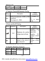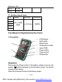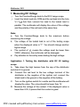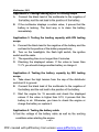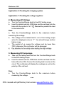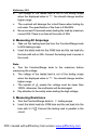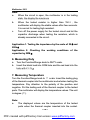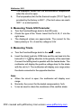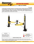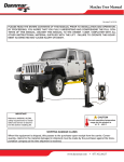
1
Multimeter 2201
AUTOMOTIVE TESTER 2201
Copyright © by Autoboss Tech. Inc.
---1---
PDF created with pdfFactory trial version www.pdffactory.com
Multimeter 2201
CONTENTS
TRADEMARK INFORMATION……………………………………………………
2
DISCLAIMER……………………………………………………………………….
3
COPYRIGHT INFORMATION…………………………………………………….
4
PRECAUTIONS…………………………………………………………………….
5
INTRODUCTION…………………………………………………………………...
8
TECHNICAL PARAMETER……………………………………………………….
10
FRONT BOARD OF DIGITAL AUTOMOTIVE TESTER……………………….
13
OPERATION………………………………………………………………………..
13
MEASURING DC VOLTAGE……………………………………………………...
14
MEASUREING AC VOLTAGE……………………………………………………
16
MEASURING DC AMPERAGE…………………………………………………..
16
MEASURING AC AMPERAGE…………………………………………………..
17
MEASURING RESISTACNE……………………………………………………..
17
MEASURING DUTY……………………………………………………………….
18
MEASURING TEMPERATURE…………………………………………………..
18
MEASURING TRIODE hFE PARAMETER……………………………………...
19
MEASUREING TROIDE…………………………………………………………..
19
ON-OFF TESTING…………………………………………………………………
20
---2---
PDF created with pdfFactory trial version www.pdffactory.com
Multimeter 2201
HOLDING FUNCTION…………………………………………………………….
20
DW ELL MEASURING……………………………………………………………..
20
RPM MEASURING………………………………………………………………...
21
MECHANICAL PROTECTION……………………………………………………
22
SELECTING ANGEL OF THE MULTIMETER………………………………….
23
MAITENANCE……………………………………………………………………...
23
ACCESSORY………………………………………………………………………
24
OPTION……………………………………………………………………………..
24
W ARRANTY………………………………………………………………………...
25
---3---
PDF created with pdfFactory trial version www.pdffactory.com
Multimeter 2201
Trademark Information
is a registered tradem ark of Autoboss Tech. Inc.
in China and other countries. All other AUTOBOSS tradem arks,
service m arks, dom ain nam es, logos, and com pany nam es
referred to in this m anual are either tradem arks, registered
tradem arks, service m arks, dom ain nam es, logos, com pany
nam es of or are otherwise the property of AUTOBOSS or its
affiliates. In countries where any of the AUTOBOSS tradem arks,
service m arks, dom ain nam es, logos and com pany nam es are not
registered, AUTOBOSS claim s other rights associated with
unregistered tradem arks, service m arks, dom ain nam es, logos,
and com pany nam es. Other products or com pany nam es referred
to in this m anual m ay be tradem arks of their respective owners.
You m ay not use any tradem ark, service m ark, dom ain nam e,
logo, or com pany nam e of AUTOBOSS or any third party without
permission from the owner of the applicable tradem ark, service
m ark, dom ain nam e, logo, or company nam e. You m ay contact
AUTOBOSS by sending an e-m ail to m [email protected] or
writing to 5/F, East, 304 Bldg., Shangbu Industrial Park,
Zhenxing Rd., Futian, Shenzhen, China to request written
permission to use m aterials on this m anual for purposes or for
other questions relating to this m anual.
---2---
PDF created with pdfFactory trial version www.pdffactory.com
Multimeter 2201
Disclaimer
All inform ation in this m anual is based on the latest product
inform ation and is believed accurate at the tim e of publication.
However, specifications and procedures are subject to change
without notice.
All inform ation, illustrations, and specifications contained in this
m anual are based on the latest inform ation available at the tim e of
publication. The right is reserved to m ake change at any tim e
without obligation to notify any person or organization of such
revisions or changes. Furtherm ore, AUTOBOSS shall not be
liable for errors contained herein or for incidental or consequential
dam ages (including lost profits) in connection with the furnishing,
perform ance or use of this m aterial.
To take full advantage of the unit, you should be familiar with the
OEM com puter system s that are supported.
This m anual tells you how to use the unit to perform diagnostic
test and to find possible locations of vehicle problem s. It does
NOT tell you how to correct the problem s. Consult your OEM
vehicle service m anual for repair instruction.
If you experience a problem obtaining service data from a vehicle,
it m ay be due to a vehicle m anufacturing design change.
---3---
PDF created with pdfFactory trial version www.pdffactory.com
Multimeter 2201
Copyright Information
All rights reserved. Printed in the People’s Republic of China. No
part of this publication m ay be reproduced, stored in a retrieval
system , or duplicated or transm itted in any m anner or by an y
m eans, electronic, m echanical, photocopying, recording without
prior written perm ission of AUTOBOSS. The inform ation
contained herein is designed only for the use of this unit.
AUTOBOSS is not responsible for any use of this inform ation as
applied to other units.
Neither AUTOBOSS nor its affiliates shall be liable to the
purchaser of this unit or third parties for dam ages, losses, costs,
or expenses incurred by purchaser or third parties as a result of
accident, m isuse, or abuse of this unit, or unauthorized
m odifications, repairs, or alterations to this unit, or failure to strictly
com ply with
AUTOBOSS operating and m aintaining instructions. AUTOBOSS
shall not be liable for any dam ages or problems arising from the
use of any options or any consum able products other than those
designated as Original AUTOBOSS Products or AUTOBOSS
Approved Products by AUTOBOSS.
General Notice: Other product nam es used herein are for
identification purposes only and m ay be trademarks of their
respective owners. AUTOBOSS disclaim s any and all rights in
those m arks.
---4---
PDF created with pdfFactory trial version www.pdffactory.com
Multimeter 2201
Precautions
1. Safety Precautions
Please read the following precautions
carefully before using Digital Autom otive
Tester 2201.
●
As the battery liquid contains
sulfuric acid, take care to avoid
direct contact of it with your skin.
Special attention should be paid to
avoid splashing battery liquid into
your eyes and keep it away from
fire.
●
There are various kinds of
poisonous venom ous compounds
such as hydrocarbon, CO, NO in
the vehicle exhaust gas. Avoid
breathing this gas. Park vehicle in a
well-ventilated place while testing.
●
The tem perature is very high while
the engine is running.
●
Avoid touching water tank and
vent-pipe and any other parts with
high tem perature.
---5---
PDF created with pdfFactory trial version www.pdffactory.com
Multimeter 2201
●
●
●
Before starting engine, be sure to apply the hand brake, and
block the front wheels and shift the gear rod in the neutral
position (m anual transm ission) or the P position (autom atic
transm ission).
Rem ember to wear protective gloves while performing the
test.
If you use the battery as power supply, connect the RED jaw
to the positive term inal, and the BLACK jaw to the negative
term inal.
2. Precautions on Testing with 2201
Read this instruction carefully before testing:
l The digital autom otive tester 2201 is designed m eeting the
requirem ents of Class II and GB 4793.1 Pollution and
IEC-1010 on Electronic Testing Instrum ent over voltage
(CATII).
l It is forbidden to m ake a test with back cover open since
there is a danger of electric shock.
l Check the harness of electronic probes dam aged or worn out
before testing.
l Electronic probes m ust be pulled out first, and then turn the
Function/Range Switch before enter or exit the current
ranges in order to protect the m echanic devices.
l The input signal m ust not exceed the nom inal value;
otherwise, it will dam age the tester.
l Do not turn Function/Scope Switch while testing.
l The potential drop will not exceed 1000V between COM and
GND; otherwise the operator will be shocked.
l Be careful when the voltage is higher than DC 60V and AC
---6---
PDF created with pdfFactory trial version www.pdffactory.com
Multimeter 2201
l
l
l
l
l
42V.
Please change a new battery for precision in tim e testing
when the sym bol of + - displayed.
Always use the sam e specification fuse for the instrum ent.
This tester is an exact electronic system , never break or hit it
while operating.
Before testing, select the correct testing scope and correct
testing leads.
Never try to repair the unit.
---7---
PDF created with pdfFactory trial version www.pdffactory.com
Multimeter 2201
Introduction
Digital Automotive Tester 2201
----Newly developed digital autom otive tester 2201 with super
design, easy operation, accurate readings, large LCD display as
well as protective m ould.
----Unique protective device for wrong operation. The testing port
of "mA" or "20A" can only be opened when the cur rent option is
chosen, otherwise, a blockage will work at the m om ent for the
protection.
----A PTC therm al elem ent is connected with the input port "VΩ
% " so as to guarantee the safety and lifetim e as well as the
switches for range scope.
----Used to test the voltage & current of DC, the voltage & current
of AC, resistor, duty, tem perature, param eter of diode and triode,
open circuit, dwell and TACH
---Portable tester for autom obile testing and m aintaining,
engineering, lab testing, production testing, field work and hom e
electric appliances repairing etc
Electric symbol
DEW LL
DC
AC
LOW BATTERY
ALARM
GND
DIOAD
BUZZ
+ !
DOUBLE ISOLATION
TACH
HIGH PRESSURE
AD OR DC
MC
MC
---8---
PDF created with pdfFactory trial version www.pdffactory.com
Multimeter 2201
CE
CYL
DUTY
Features
1. Low power consum ption CMOS double differential A/D
converter integrated circuit, autom atic zero calibration, autom atic
pole displaying, data storing, low energy consum ption and large
m easuring range
2. Accuracy of the current: ±0.5%
3. Dwell: 0.1℃-120℃
4. RPM m easuring: 10RPM-10000RPM
5. Tem perature: -20℃-1000℃
6. Autom atic power off: the power will be turned off autom atically
15 m inutes after the power on for the protection
7. Mechanical protection for full range overload
8. Maxim um value: 1999(3 1/2)
9. Large LCD display: 70x48mm , the height of the letter up to
28m m
10. Power: 9V battery (NEDA1604, 6F22 or sim ilar)
11.Low voltage alarm : + 12.Dim ension: 192x88x42m m
13.W eight: 600g (including battery and m ould)
14.W orking condition:
Tem perature: 0℃-40℃
Relative Hum idity: <85%
Tem perature: -10℃-50℃
Relative Hum idity: <85%
Optim um Tem perature: 23℃±5℃
Relative Hum idity: <75%
---9---
PDF created with pdfFactory trial version www.pdffactory.com
Multimeter 2201
Technical Parameters
1. DC Voltage
Range Accuracy
2V
20V
200V
1000V
Resolution
1m V
±(0.5%+2) 10m V
100m V
±(0.8%+3) 1V
Input Im pedance: 10MΩ
Over load protection: DC 1000V or AC 700V (effective value)
2. AC Voltage
Range Accuracy
2V
20V
200V
700V
Resolution
1m V
±(0.8%+3) 10m V
100m V
±(1.2%+5) 1V
Input im pedance: 10MΩ
Frequency: 40Hz—400Hz
Over voltage protective: DC 1000V or AC 700V (effective value)
Display: average value (sine wave effective value)
3. DC Amperage
Range
20m A
Accuracy
Resolution
±(0.8%+2) 10μA
200m A ±(1.2%+2) 100μA
20A
±(2%+5)
10m A
Over current protective: 0.2A/250A fuse (no fuse for the range of
20A)
Max. input current: 20A (less than 15s)
---10---
PDF created with pdfFactory trial version www.pdffactory.com
Multimeter 2201
Voltage drop: 200m V voltage drop for the full range
4. AC Amperage
Range
Accuracy
Resolution
10μA
20m A
±(1%+3)
200m A ±(1.8%+3) 100μA
20A
±(3%+7)
10m A
Over load protection: 0.2A/25.A fuse (no fuse fro the ranges of
20A)
Max. input current: 20A (less than 15s)
Voltage drop: 200m V voltage drop for the full range
Frequency: 40Hz—400Hz
Display: average value (sine wave effective value)
5. Resistor
Range
Accuracy
Resolution
200Ω
±(0.8%+3) 0.1Ω
20KΩ
10Ω
±(0.8%+2)
200KΩ
100Ω
20MΩ ±(1%+5)
10KΩ
Over load protection: 250V, DC or AC effective value
Open circuit voltage: <700m V
6. Duty
Range
Accuracy
0.1%--99.9% ±(1%+5)
7. Temperature
Range
Accuracy Resolution
-20℃—0℃
±(5%+5) 1℃
---11---
PDF created with pdfFactory trial version www.pdffactory.com
Multimeter 2201
0℃—400℃
400℃--1000℃
±(1%+3) 1℃
±(2%+4) 1℃
8. Transistor Triode hFE Parameter Testing
Range
hFE
Testing
Conditions
Ib is about 10μ
Testing the param eter of NPN or PNP
A,
triode hFE
Vce is about
The range is 0—1000ß
2.8V
Description
9. Diode and On-Off Testing
Range Resolution
1m V
Description
Testing
Conditions
Positive
DC
amperage
is
Displaying the positive about 1m V
Negative
DC
voltage drop for Diode
voltage is about
2.8V
Buzz will work when the Open
circuit
-resistor of the circuit is voltage is about
lower than 50Ω
2.8V
Over load protection: 250V, DC or AC effective value
10. Dwell for Distributor Contactor
Cylinder
3CYL
Range
0—120
4CYL
5CYL
0—90°
0—72°
Accuracy
Resolution
±(1.2%+2)
0.1°
---12---
PDF created with pdfFactory trial version www.pdffactory.com
Multimeter 2201
6CYL
8CYL
0—60°
0—45°
11. Rotation Speed (rpm)
CYL
Range
Accuracy
3CYL
4CYL
5CYL
6CYL
500—10000
±(1.2%+2)
RPM
Resolution
10RPM
8CYL
Front Board of Digital Automotive Tester
1. Description
①
⑥
②
③
⑦
④
⑤
①
②
③
④
⑤
⑥
⑦
⑧
LCD Display
Hold switch
Range knob
Tem perature socket
Insert COM
Power switch
Triode socket
Sliding plate
⑧
Operation
Press down the Power switch. If the battery voltage is too low, the
sym bol + - will be displayed on the left upper screen. You should
change a new battery.
Select the required functions and testing ranges.
---13---
PDF created with pdfFactory trial version www.pdffactory.com
Multimeter 2201
1. Measuring DC Voltage
① Turn the Function/Range knob to the DCV range scope.
② Insert the black lead into COM and the red lead into the hole
VΩ% . And then connect the lead to the tested load in
parallel. The m ultim eter will display the value of the voltage
and the polarity of the red lead at the sam e tim e.
Note:
a. Turn the Function/Range knob to the m axim um before
m easuring the voltage.
b. The voltage of the tested load is out of the testing scope
when the displayed value is “1”. You should change another
higher range.
c.
d.
The sym bol of ! m eans the voltage m ust be lower than
1000V; otherwise, the m ultim eter will be dam aged.
Pay attention to the safety when testing the high voltage.
Application 1. Testing the distributor with DC 2V testing
scope
A. Take down the high tension from the cap of the distributor
and short it to ground.
B. Connect the red lead to the low voltage term inal of the
distributor or the negative of the ignition coil; connect the
black lead to the ground or the negative of the battery,
C. Turn on the ignition switch for a while and the m ultim eter will
display the value. The value should be lower than 1V.
D. Measure the voltage of the contact. If the displayed value is
lower than 0.2V, it proves that the contact is good.
---14---
PDF created with pdfFactory trial version www.pdffactory.com
Multimeter 2201
Application 2. Leakage testing by DV 2V testing scope
A. Connect the black lead of the m ultim eter to the negative of
the battery and the red lead to the positive of the battery.
B. If the m ultim eter displays a certain value, it proves that the
battery is leaking. The best way is to clean the batter y
im m ediately.
Application 3. Testing the loading capacity with 20V testing
scope
A. Connect the black lead to the negative of the batter y and the
red lead to the positive of the battery respectively.
B. Turn on the headlights, the flash light switch, the ignition
switch and the radio.
C. The operating tim e is no longer than 2 m inutes.
D. Checking the displayed values. If the value is lower than
11.7V, you should change another battery or charge it.
Application 4. Testing the battery capacity by 20V testing
scope
A. Take down the high tension from the cap of the distributor
and short it to ground.
B. Connect the black lead of the m ultim eter to the negative of
the battery and the red lead to the positive of the battery.
C. Start the engine for 15 seconds and check the displayed
values. If the value is higher than 9.1V, it proves that the
battery is ok. Otherwise, you have to check the engine or
charge the battery or replace it.
Application 5. Testing the battery cable
A. Test the voltage of the battery cable as well as the working
conditions when starting the engine
---15---
PDF created with pdfFactory trial version www.pdffactory.com
Multimeter 2201
Application 6. Checking the charging system
Application 7. Checking the voltage regulator
2. Measuring AC Voltage
a.
b.
Turn the Function/Range knob to the ACV testing scope
Insert the black lead into COM hole and the red lead into the
hole with the sym bol of VΩ% . Meanwhile, parallel the lead
to the tested load.
Note:
a. Turn the Function/Range knob to the m axim um before
m easuring the voltage.
b. The voltage of the tested load is out of the testing scope
when the displayed value is “1”. You should hange another
higher range.
c. The sym bol of ! m eans the voltage m ust be lower than
700V; otherwise, the m ultim eter will be dam aged.
d. Pay attention to the safety when testing the high voltage.
3. Measuring DC Amperage
a.
b.
Take out the testing lead and turn the Function/Range knob
to the DCA testing scope
Insert the black lead into COM hole and the red lead into the
hole with mA or 20A. Connect the testing lead in series in the
circuit. The m ultim eter will display the readings as well as the
polarity of the red lead.
Note:
a. Turn the Function/Range knob to the m axim um before
m easuring the voltage.
---16---
PDF created with pdfFactory trial version www.pdffactory.com
Multimeter 2201
b.
c.
d.
The voltage of the tested load is out of the testing scope
when the displayed value is “1”. You should change another
higher range.
The overload will dam age the in-built fuses when testing by
m A scale. The specification of the fuse is 0.2A/250V
Never exceed 15 seconds when testing the load b y m axim um
current 20A. There is no fuse at the scale of 20A.
4. Measuring AC Amperage
a.
b.
Take out the testing lead and turn the Function/Range knob
to ACA testing scope.
Insert the black lead into the COM hole and the red lead into
the hole with mA or 20A. Connect the testing lead in series in
the circuit.
Note:
a. Turn the Function/Range knob to the m axim um before
m easuring the voltage.
b. The voltage of the tested load is out of the testing scope
when the displayed value is “1”. You should change another
higher range.
c.
d.
The sym bol of ! m eans the voltage m ust be lower than
1000V; otherwise, the m ultim eter will be dam aged.
Pay attention to the safety when testing the high voltage.
5. Measuring Resistance
a.
b.
Turn the Function/Range knob to Ω testing scope.
Insert the black lead into COM hole and the red lead into the
hole with VΩ% . Connect the testing lead in parallel in the
circuit.
---17---
PDF created with pdfFactory trial version www.pdffactory.com
Multimeter 2201
Note:
a.
W hen the circuit is open, the m ultim eter is in the testing
state, the display the m axim um
b.
W hen the tested resistor is higher than 1M Ω , the
m ulitim eter will display the stable values after few seconds.
It is norm al for testing high resistant.
c.
Turn off the power supply for the tested circuit and let the
capacitor discharge when testing the resistors, which is
already connected in the circuit.
Application 1. Testing the impedance by the scale of 20Ωand
200kΩ
Application 2. Checking the working conditions of the
capacitor by 20MΩ
6. Measuring Duty
a.
b.
Turn the Function/Range knob to DUTY scale.
Insert the black lead into COM hole and the red lead into the
hole with VΩ% .
7. Measuring Temperature
Turn the Function/Range knob to ℃ scale. Insert the testing plug
of the therm al coupler into the m ulitim eter socket when testing the
temperature. Pay attention to the polarity of the positive and
negative. Put the testing end of the therm al coupler to the tested
parts. The m ultim eter will display the tem perature values. The unit
is degree (℃).
Note:
a.
The displayed values are the tem perature of the tested
parts when the therm al coupler inserted into the socket.
---18---
PDF created with pdfFactory trial version www.pdffactory.com
Multimeter 2201
b.
The displayed values are the environm ental temperature
when the circuit is open.
The tem perature lim it for the therm al coupler (TP-01 Type K)
provided by the factory is 250℃. ( The lim it value can reach
300℃ in a short period.)
8. Measuring Triode hFE Parameter
a.
b.
c.
Turn the Function/Range knob to the hFE scale.
Check the type of the Triode. Insert the Pin E, B, C into the
right holes.
The displayed values are approxim ate. The current for the
basic polarity is 10μA and the voltage is 2.8V
9. Measuring Triode
a. Turn the Function/Range knob to the
b.
scale.
Insert the black lead into COM hole and the red lead into the
hole with VΩ% . Pay attention to the polarity of the read lead.
Connect the testing lead in parallel with the tested diode. The
m ultim eter will display the positive voltage drop for the diode
with the unit is V. The m ultim eter will display over range when
the diode connected in the opposite direction.
Note:
a. W hen the circuit is open, the m ultim eter will display over
range.
b. Norm ally, the current for the tested com ponents is 1m A.
c. It can be used to check the conditions of the rectifier diode.
---19---
PDF created with pdfFactory trial version www.pdffactory.com
Multimeter 2201
10. On-Off Testing
a.
Turn the Function/Range knob to the scale of
b.
Insert the black lead into COM hole and the red lead into the
hole with VΩ% . Connect the testing lead in series in the
circuit.
The buzz will m ake the sound of Di-Di when the resistance is
lower than 50Ω.
c.
Note: Check the circuit when the power off otherwise an error will
com e up.
11. Holding Function
The m ultim eter will display the letter H when the Hold button
pressed. It is easy for you to read the m easured values with this
function. The letter H will disappear when the button pressed
again.
12. Dwell Measuring
a.
b.
c.
d.
Insert the black lead into COM hole and the red lead into the
hole with VΩ% .
Turn the switch to the scale of DW ELL according to the
cylinder num bers.
Connect the black lead to ground or the negative of the
battery and the red lead to the low voltage term inal of the
distributor. See the following pictures
Start the engine and read the dwell by the m ultim eter.
---20---
PDF created with pdfFactory trial version www.pdffactory.com
Multimeter 2201
Black cable
Red cable
Ignition Switch
Battery
Plug
Ignition Coil
Distributor
Picture for Dwell
13. RPM Measuring
a.
b.
c.
d.
Insert the black lead into COM hole and the red lead into the
hole with VΩ% .
Turn the switch to the TACH scale according to the engine
cylinders.
Short the black lead to ground or the negative of the battery
and the red lead to the low voltage term inal of the distributor
or the negative of the ignition coil. See the following pictures.
Start the engine. The engine speed is the m easured values
tim es 10. The unit is rpm .
---21---
PDF created with pdfFactory trial version www.pdffactory.com
Multimeter 2201
Black cable
Red cable
Ignition Switch
Battery
Plug
Ignition Coil
Distributor
Picture for RPM testing
14. Mechanical Protection
The m ultim eter has a m ovable plate. It can protect error operation.
The plate can m ove between the function and range knob. The
m echanical protection is listed as following:
(The sym bol ● m eans the hole is blocked. The black lead can
insert into the hole)
The hole blocked
Position of Switch
VΩ%
Voltage for DC and AC
Current over 20A for DC
●
and AC
mA
●
20A
●
●
---22---
PDF created with pdfFactory trial version www.pdffactory.com
Multimeter 2201
Current within 20A for DC
●
and AC
●
Resistance Ω
●
●
●
●
Triode hFE param eter
Duty
Tem perature ℃
Dwell,rpm
●
●
●
●
●
●
●
●
The Function/Range knob cannot m ove if you forget to pull out the
testing leads.
Pull out the testing leads before turning the Function/Range knob
otherwise the m echanical protection will be dam aged.
15. Selecting the angel of the Multimeter
A protection m ould provided for the protection. You can adjust the
holder for the readings at different angles.
Maintenance
Digital autom otive tester 2201 is an accurate tool. It should be
kept carefully.
1. Do not test the DC voltage higher than 1000V or AC
voltage higher than 700V with digital autom otive tester
2201.
2. Pull out the testing leads before turn the Function/Range
knob. Otherwise, the m echanical protection will be
dam aged.
3. Do not use the digital autom otive tester 2201 if the back
cover is not in the right position.
---23---
PDF created with pdfFactory trial version www.pdffactory.com
Multimeter 2201
4. Pull out the testing leads or turn off the power before
exchange a new battery. Turn out the screw and push the
battery cover. Take down the batter y cover and change a
new battery with the sam e specification.
5. Pull out the testing leads or turn off the power before
exchange the fuse. Turn out the screw and open the back
cover of the m ultim eter. Change a new fuse with the
sam e specification. Close the back cover and screw it.
6. The specification of the fuse is 0.2A/250V
7. Take out the battery and put it in dry and ventilation
places if you DO NOT use the m ultim eter for a long tim e.
8. DO NOT try to change the interior circuit
Accessory
1.
2.
3.
4.
5.
User Manual
Quality Certificate
Protection Mould
Testing Leads
Type K Therm al Coupler
Op t io n
SMD clamper: can be used to test the param eter of the resistance,
capacitance, inductance, and transistor.
---24---
PDF created with pdfFactory trial version www.pdffactory.com
Multimeter 2201
Warranty
THIS WARRANTY IS EXPRESSLY LIMITED TO ORIGINAL
PERSONS WHO PURCHASE AUTOBOSS PRODUCTS FOR
PURPOSES OF RESALE.
AUTOBOSS is warranted against defects in materials and
workm anship. This warranty does not cover any Autoboss that
has been abused, altered, used for a purpose other than that for
which it was intended, or used in a m anner inconsistent with
instructions regarding use. The sole and exclusive rem edy for any
Autoboss found to be defective is repair or replacem ent, at the
option of AUTOBOSS in accordance with procedures established
by AUTOBOSS.
In no event shall AUTOBOSS be liable for any dam ages, direct or
indirect, special, incidental or consequential or compensatory,
including, without lim itation, lost profits, for any representations,
breaches or defaults arising out of the use of this m anual.
Custom er agrees to indem nify AUTOBOSS and hold it harm less
against all claim s and dam ages, including without lim itation,
reasonable attorney’s fees arising out of the use of this m anual,
unless such claim s or dam ages result from the infringem ent of
any copyright or other proprietary right of any third party. No one
is authorized to m ake any statem ent or representation altering the
term s of this warranty. No agent, em ployee, or representative of
AUTOBOSS has any authority to bind AUTOBOSS to any
affirm ation, representation, or warranty concerning AUTOBOSS
autom otive m eters, except as stated herein.
---25---
PDF created with pdfFactory trial version www.pdffactory.com
Multimeter 2201
Disclaimer
THE ABOVE WARRANTY IS IN LIEU OF ANY OTHER WARRANTY,
EXPRESS
OR
IMPLIED,
INCLUDING
ANY
WARRANTY
OF
M ERCHANTABILITY OR FITNESS FOR A PARTICULAR PURPOSE.
Specifications contained in this book are based on the
m anufacturers’ inform ation and were believed accurate at the
tim e of publication. All information, illustrations, and specifications
contained in this technical m anual are based on the latest
inform ation available at the tim e of publication.
The right is reserved to m ake change at any tim e without
obligation to notify any person or organization of such revisions or
changes. Furtherm ore, AUTOBOSS shall not be liable for errors
contained herein or for incidental or consequential dam ages
(including lost profits) in connection with the furnishing,
perform ance or use of this m aterial. To take full advantage of the
unit, you should be fam iliar with the OEM computer system s that
are supported.
This m anual tells you how to use the unit to perform diagnostic
test and find possible locations of vehicle problem s. It does NOT
tell you how to correct the problems. Consult your OEM vehicle
service m anual for repair instruction. If you experience a problem
obtaining service data from a vehicle, it m ay be due to a vehicle
m anufacturing design change. Vehicle m anufacturers now
introduce new product lines year-round. To obtain test data on a
mid-year vehicle, you m ay need to program the tester to the next
m odel year available in the software cartridge, not the actual VIN
year of the vehicle being tested.
---26---
PDF created with pdfFactory trial version www.pdffactory.com
Multimeter 2201
Order Information
Replaceable and optional parts can be ordered directly from your
AUTOBOSS authorized tool supplier. Your order should include
the following inform ation:
1. Quantity
2. Part num ber
3. Item description
Customer Service
For any quality problem s, please contact the local distributor or
direct contact Autoboss Tech. Inc.
Autoboss Tech. Inc.
5/F, East, 304 Bldg., Shangbu Industrial Park, Zhenxing Rd., Futian,
Shenzhen, China
Tel: 0086-755-83285146
Fax: 0086-755-82170248
E-m ail: [email protected]
Website: www.autoboss.net
---27---
PDF created with pdfFactory trial version www.pdffactory.com