1
INSTALLATION INSTRUCTIONS
80
EIGHTY
ISO 9001
AND OWNER'S MANUAL
www.seastarsolutions.com
Hydraulic Engine Controls – 04 Series
way,
r
u
o
y
it
o
d
Before yopulease try it our way
Notice to Boat Manufacturer
or Installer
Throughout this publication, Warnings and Cautions (accompanied
by the International Hazard Symbol
) are used to alert the
manufacturer or installer to special instructions concerning a
particular service or operation that may be hazardous if performed
incorrectly or carelessly.
Observe Them Carefully!
These “safety alerts” alone, cannot eliminate the hazards that they
signal. Strict compliance to these special instructions when
performing the installation and maintenance plus “common sense”
operation are major accident prevention measures.
DANGER
Immediate hazards
which WILL result in
severe personal injury
or death.
WARNING
WARNING
Hazards or unsafe
practices which
COULD result in
severe personal injury
or death.
CAUTION
Hazards or unsafe
practices which
COULD result in
minor injury or
product or property
damage.
NOTICE
Information which
is important to
proper installation or
maintenance, but is
not hazard-related.
Cleaning fluids containing ammonia, acids or any other corrosive
ingredients must not be used for cleaning any part of this Hydraulic
Steering System. Failure to comply will cause serious damage to
the steering system, resulting in possible loss of steering, causing
property damage, personal injury and/or death.
Don’t compromise performance... use genuine
Hynautic parts only!
• Hynautic Control Senders
• Hynautic Control Reservoirs
• Hynautic Control Fluid
• Hynautic Control Slave Units
• Hynautic Control Tubing
Substituting non Hynautic parts in any part of the Hynautic hydraulic
steering system, may seriously compromise system performance.
This manual should be kept on board your vessel
Index
Introduction ............................................................................... ii
Preparation for Installation........................................................... 1
Component Installation................................................................ 1
Sender Installation................................................................. 1
Throttle Slave Installation........................................................ 3
Clutch Slave Installation.......................................................... 6
R-13 Reservoir Installation...................................................... 8
R-04 Reservoir Installation...................................................... 8
MCV-04 Charging Valve Installation.......................................... 9
Tubing Installation and Connection............................................. 10
Rules for Routing Tubing....................................................... 10
Install Tubing Between Senders and Slaves............................ 11
Copper Tubing...................................................................... 12
Filling and Bleeding the System...................................................15
Filling the System................................................................. 15
Bleeding the System, at Slave............................................... 15
Bleeding the System, at Senders........................................... 16
System Fluid............................................................................. 17
Making the System Operational . ............................................... 17
Synchronizing the Controls.................................................... 17
Connecting Engine Controls.................................................. 17
Operation & Maintenance.......................................................... 18
Throttle Senders.................................................................. 18
Clutch Senders.................................................................... 18
Maintenance Schedule......................................................... 18
Parts List.................................................................................. 19
System Parts List (Nylon Tubing)............................................ 19
System Parts List (Copper Tubing)......................................... 20
Sender Assembly................................................................. 21
Ball & Tee Handle Installation................................................ 22
ST-06 Throttle Slave Assembly.............................................. 23
SS-04 Transmission Slave Assembly..................................... 24
Optional Neutral Safety Switch Kit SSH-01.................................. 25
Templates................................................................................. 29
CDF-04 Mounting Plate.............................................................. 31
Tubing Diagrams ..................................................................... 33
Plan I – Twin Engine, One Station........................................... 33
Plan II – Twin Engine, Two Station......................................... 34
Plan III – Twin Engine, Three Station....................................... 35
Plan IV – Twin Engine, Four Station........................................ 36
Supplemental Throttle Control Circuits........................................ 37
Plan I-S................................................................................ 37
Plan II-S............................................................................... 37
Plan III-S............................................................................. 38
Plan IV-S............................................................................. 38
Troubleshooting Guide............................................................... 39
Technical Information................................................................ 42
Statement of Limited Warranty.................................................. 43
Installation Instructions & Owner's Manual
i
INTRODUCTION
CAUTION
SeaStar Solutions Engine
Control System — Why it
Works
ii
This system does NOT use oil or Steering Fluid. Use HA5455
Hynautic shift and throttle control fluid ONLY. DO NOT use
stop-leak type anti-freeze.
The movement of a sender’s control arm transmits mechanical energy
to an internal piston which in turn pushes hydraulic fluid through the
other corresponding control senders and single control slave. This
movement of hydraulic fluid drives a piston in each of the senders
and slave. The movement of the individual pistons causes shaft
rotation in each unit.
The piston in each of the individual control senders and slaves has
two small valves which are opened when the piston reaches the end
of its stroke, allowing additional fluid to pass through the system. By
allowing this flow of hydraulic fluid, the controls may be synchronized
with each other by moving the control arm at one control station
from stop to stop.
The control slave is very similar to the control sender, except the
body is a rectangular block. An over-travel bungee is used in the
linkage between the slave arm and engine control arm to assure
that the slave can reach the end of its stroke in each direction. The
slave for the transmission has a built-in detent mechanism to
indicate neutral position.
On most engines the throttle exerts considerable force to return to
the idle position. Each throttle slave is equipped with a pilot check
valve which locks the throttle slave in the position it has taken in
response to the sender. The throttle slave can be driven only by the
sender, it cannot drive the sender.
Extra hydraulic fluid and a pressure head for the system is maintained
by the system’s reservoir. The reservoir is charged with 80 psi of air
over the hydraulic fluid within it. This keeps the entire system under
pressure at all times and prevents a vacuum from existing on the
back side of any piston when the system is operated.
Fluid-flow to and from the reservoir is regulated by a charging valve
located on the bottom of the reservoir. This valve is necessary to
keep the system under pressure, and to prevent excessive pressures
caused by the expansion of fluid when the fluid becomes warm.
Nylon tubing is used to pipe the system for two reasons: (1) ease of
installation, (2) nylon tubing expands and contracts in very much the
same manner as the hydraulic fluid (a most important factor). The
expansion and contraction of the tubing reduces drift of the controls
as temperature changes, thereby helping to keep all the components
of the system synchronized. The tubing is virgin nylon, which has
been heat and light stabilized and contains no plasticizers. The burst
pressure of the tubing is in excess of 1200 psi.
Hynautic Hydraulic Engine Controls – 04 Series
PREPARATION FOR
INSTALLATION
CAUTION
Dirt and foreign matter in the hydraulic system cause damage and
malfunction. It is extremely important to keep tubing and fittings
clean when installing and connecting components. Cut tube cleanly
and tape the open end while running tubing.
Before installation is started, the parts list should be checked to verify
that a complete system has been received. Parts lists are located on
page 19 and page 20.
It is advised that all system components be installed, (senders, shift,
throttle slaves, and reservoir) prior to running the system tubing. This
allows the tubing to be run between two definite points with less
chance of an error.
Should it become necessary for the tubing to be strung first, a system
of marking the different tubing runs should be used.
COMPONENT INSTALLATION
Components have red plastic plugs installed in their ports to keep out
foreign matter. As you remove these red plastic plugs, replace them
immediately with the proper adapter; then install the red plugs into the
adapters until you are ready to connect tubing.
Use Loctite® hydraulic sealant on all NPT fittings prior to installation.
DO NOT use teflon tape or pipe dope.
Sender Installation
NOTICE
1 Locate sender on panel so that the control arm’s arc will not interfere
with the ship’s wheel or panel. Be certain that access is available
to the small bleeder screw at the top of each sender head.
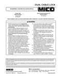
The design of the new Engine Control "T" handle requires a
minimum distance between control heads to provide adequate
handle clearance when two sets of controls are mounted side by
side. See Figure 1.
This minimum distance does not apply to installations using the
optional "knob" style control handles.
2 Using the template provided in the appendix, mark and cut a hole
for the sender. Page 29 shows the proper templates for the
single head and side by side sender mounting options. Refer to
Figure 1 for minimum distance required when mounting two sets
of controls side by side.
3 Drill 7/16" holes in the panel for the mounting bolts.
4 Set sender in place and check to see if all mounting holes match up.
Installation Instructions & Owner's Manual
1
HYNAUTIC CONTROLS
COMPONENT INSTALLATION
NOTICE
If the area under the control
panel is too confined to allow
the tubing to be connected with
moderate ease, do not secure
the sender at this time. Proceed
with the installation of the
remaining senders per Steps 1
through 5. The sender may be
secured after the tubing has
been connected to it.
5 The sender’s ports are tapped 1/4" NPTF. Suitable adapters
must be installed to accept the tubing used. It is more convenient
to install these adapters prior to mounting the senders.
(Instructions for copper tubing installations are onpage 12.)
6 Secure senders per Figure 2 for single head, or Figure 3 for side
by side mounting.
7 The sender’s handle position may be set within limits by loosening
the tightening screw (using a 1/4" allen wrench) in the lower end
of the arm and then rotating the arm as desired and resetting the
screw. After the arm is set, it will have a 115° maximum arc.
8 Secure the remaining senders per Steps 1 through 7.
NOTICE
The minimum distance
does not apply to
installations using
the "knob style"
control handles.
3.5" MINIMUM
BETWEEN PLATES
3.75" MINIMUM
BETWEEN HEADS
Figure 1. Mounting "T" Handle Controls Side by Side.
PANEL
CDF-04
MOUNTING
PLATE
CONTROL
PANEL
WASHER
WASHER
MOUNTING
BOLT
Figure 2. Single Head Sender.
2
MOUNTING
BOLT
Figure 3. Side-By-Side Senders.
Hynautic Hydraulic Engine Controls – 04 Series
HYNAUTIC CONTROLS
COMPONENT INSTALLATION
Throttle Slave Installation
NOTICE
The standard SeaStar Solutions
System, MC-04, uses the ST-06
Integrated Throttle Slave. You may
have chosen to order a nonstandard system which includes
the ST-04 Throttle Slave and
STV-10 Lock-out Valve. Depending
on which system you have, follow
the corresponding installation
instructions in this section.
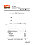
CAUTION
SeaStar Solutions throttle slaves must be mounted so that at the
mid-stroke of both the engine’s throttle arm and the slave’s control
arm, they are: 1) In the same plane; 2) parallel to each other; and 3)
right angles will be formed between the connecting linkage and each
arm. See Figure 4.
If these criteria are met, an ideal installation will result.
A spring bungee-ball joint assembly is furnished with each throttle
slave. It is installed in the slave arm-to- throttle linkage according to
Figure 4. It allows up to 3/16" slave arm over-travel in each direction.
This over-travel lets the slave cylinder travel its full stroke and still
provide full travel to the throttle arm. You must use almost all of the
slave travel, or about 75°, to operate the throttle. The slave must go
full stroke in each direction in order to synchronize the system.
The throttle slave’s arm may be set to any desired position by loosening
the tightening screw (using a 3/16" allen wrench) in the lower end of
the arm and then rotating the arm as desired and resetting the screw.
After the arm is set, it will have a 78° maximum arc.
The Throttle Slave must not be mounted to any surface exceeding
220° F (103° C). If mounting in a "hot spot" is unavoidable, the
slave must be insulated from the heat.
BUNGEE-BALL
JOINT ASSEMBLY
(850081)
BALL JOINT
(670010)
LOCK NUTS
(1/4-20)
90˚
1/4-20
THREADED
ROD
SLAVE
ARM
90˚
THROTTLE ARM
Figure 4. Throttle Slave to Throttle Arm Installation.
Steps 1 through 8 apply to both ST-04 and ST-06 Systems
1 Secure the mounting bracket to the engine. A suitable bracket
must be fabricated.
2 Secure the throttle slave to the mounting bracket using 3/8-16
mounting bolts.
3 Install a lock nut and bungee-ball joint on the end of a 1/4-20
stainless or brass threaded rod.
Installation Instructions & Owner's Manual
3
HYNAUTIC CONTROLS
COMPONENT INSTALLATION
4 Position the throttle slave to its mid-stroke and connect the
bungee end of the 1/4-20 threaded rod to it (not provided).
5 Position the engine’s throttle arm to its mid-stroke. Determine
the length of threaded rod required and cut off the excess.
6 Connect a lock nut and a ball-joint to the engine’s throttle arm
and the free end of the threaded rod.
7 Find the proper hole in the slave arm to provide a linkage length
combination that will allow idle to full throttle on the engine,
using all but a few degrees of slave arm travel in each direction.
By adjusting the ball-joint and bungee, a fine adjustment in both
directions can be achieved. Be sure the slave arm can over-travel
through the bungee to the end of its stroke in each direction.
8 After determining the correct rod length, securely lock the balljoint and bungee assembly to the threaded rod with lock nuts
provided. Disconnect the linkage from the throttle slave’s arm.
ST-06 System ONLY
9 To prevent engine retard due to governor spring or vibration, a
pilot check valve is built into the ST-06 Throttle Slave.h the
bungee to the end of its stroke in each direction.
NOTICE
This built-in valve will lock the slave arm in place allowing it to be
moved only by the sender.
10 Locate a tee and bleeder valve on the throttle slave and install
suitable adapters to accept tubing, per Figure 5.
NOTICE
Tube connectors are installed on the tubing per instructions under
“Tubing Installation” and “Connection” on page 10.
11 Verify all fittings installed have been tightened. Repeat these
throttle slave installation procedures for the second engine.
CAUTION
Dirt and foreign matter in the hydraulic system cause damage and
malfunction. It is extremely important to keep tubing and fittings
clean when installing and connecting components.
ST-04 System ONLY
9 To prevent engine retard due to governor spring or vibration, a
separate STV-10 lock-out valve is used with the ST-04 Throttle
Slave.
NOTICE
If the throttle slave is in a limited space, it may be removed from the
bracket during the lock-out valve installation. The STV-10 Lock Out
Valve must be plumbed as shown in Figure 6. The lock-out valve will
lock the slaves arm and allow it to be moved by only the sender.
The check valve and slave must be mounted in close proximity to
one another. If they're not, abnormal locking action and poor
performance will result.
10 Install the lock-out valve on the throttle slave and secure it using
clean lubricant or Loctite hydraulic sealant on the threads.
Install appropriate adapters to accept tubing. Refer to Figure 6.
4
Hynautic Hydraulic Engine Controls – 04 Series
HYNAUTIC CONTROLS
COMPONENT INSTALLATION
TO CONTROL STATIONS
NYLON TUBING
5/16" O.D. N-2
HYNAUTIC TUBE FITTING ASSEMBLY
NUT (530015)
LOCK RING (530025)
INSERT (530045)
O-RING (002222)
ADAPTER 1/4" PIPE X 5/16 TUBE
(530175)
BLEEDER ASSEMBLY
(690010)
1/4" PIPE NIPPLE
(690551)
1/4" PIPE TEE
(690441)
78˚
CONTROL ARM MAY BE ROTATED
TO ANY ANGLE ON SHAFT
Figure 5. ST-06 Integrated Throttle Slave with Tee and Bleeder Valve Installation.
NOTICE
Tube connectors are installed on the tubing per instructions under
“Tubing Installation” and “Connection.”
11 Using a short piece of tubing provided, connect the open port on
the tee to the S2 port on the lock-out valve. See Figure 6. (See
Figure 15 for Copper Tubing connection.) Plug open fittings at
the V1 and V2 ports.
12 Verify all fittings installed have been tightened. Repeat these
throttle slave installation procedures for the second engine.
ADAPTER 1/4" PIPE
5/16" TUBE
(530175)
BLEEDER
ASSEMBLY
(690010)
1/4" PIPE TEE
(690441)
NUT (530015)
LOCK RING (530025)
INSERT (530045)
O-RING (002222)
ADAPTER 1/4" PIPE
5/16" TUBE
(530175)
HYNAUTIC TUBE
FITTING ASSEMBLY
NYLON TUBING
5/16" O.D. N-2
V2
V1
NIPPLE 1/4"
PIPE
(690551)
S2
NYLON TUBING
5/16" O.D. N-2
78˚
S1
NIPPLE 1/4" PIPE
(690551)
TO CONTROL
STATIONS
HYNAUTIC TUBE
FITTING ASSEMBLY
CONTROL ARM MAY
BE ROTATED TO ANY
POSITION ON SHAFT
ST-04
THROTTLE SLAVE
ADAPTER 1/4"
PIPE 5/16" TUBE
(530175)
1/4" PIPE TEE
(690441)
ASSEMBLY
STV-10 LOCK-OUT VALVE
(950119)
Figure 6. ST-04 Throttle Slave with STV-10 Lock-Out Valve.
Installation Instructions & Owner's Manual
5
HYNAUTIC CONTROLS
COMPONENT INSTALLATION
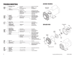
Clutch Slave Installation
The SeaStar Solutions clutch slave must be mounted so that when the
engine’s transmission is in neutral and the Morse clutch slave’s arm is
at its mid-stroke, both arms will be: 1) in the same plane; 2) parallel to
each other; and 3) right angles will be formed between connecting
linkage and each arm, see Figure 7.
SLAVE ARM
LOCK NUT
LOCK NUT
BALL JOINT
(670010)
90˚
1/4-20
THREADED
ROD
BALL JOINT
(670010)
90˚
CLUTCH ARM
Figure 7. Proper Clutch Slave to Throttle Arm Installation.
NOTICE
The clutch slave’s arm may be set to any desired position by
loosening the tightening screw (using a 3/16" allen wrench) in the
lower end of the arm. Rotate arm as desired and reset the screw.
After the arm is set it will have a 78° maximum arc.
1 Secure mounting bracket to the engine. A suitable bracket must
be fabricated.
2 Secure the transmission slave to the mounting bracket using the
3/8-16 mounting bolts.
3 Set the transmission in the neutral position, and the clutch
slave’s arm at its mid-stroke.
4 Loosen the set screw in the detent ring on the clutch slave and
rotate the detent ring to the full detent position. To locate the
detent ring, see Figure 8.
5 Secure detent ring in this position by tightening the set screw.
6 Install a lock nut and ball joint on the end of the 1/4-20 stainless
steel or brass threaded rod (not provided).
7 Position the clutch slave to its mid-stroke and connect the ball
joint end of the 1/4-20 threaded rod to it.
8 Position the engine’s clutch arm to neutral, determine the proper
length of the threaded rod required and cut off the excess.
9 Install a lock nut and ball joint on the other end of the threaded rod.
6
Hynautic Hydraulic Engine Controls – 04 Series
HYNAUTIC CONTROLS
COMPONENT INSTALLATION
DETENT RING
CONTROL ARM LOCK-SCREW
DETENT RING LOCK-SCREW
240357
Figure 8. Detent Ring Location.
10 By locating the slave arm ball-joint in its proper hole and adjusting
both ball joint on the threaded rod, find the correct length of
linkage that will allow both "full- forward" and "fullreverse" on
the transmission for full throw on the clutch slave arm.
11 After determining the correct linkage length, securely lock the
ball-joints to the threaded rod with lock-nuts provided. Disconnect
the linkage from the clutch slave’s arm.
12 Locate and secure in place two tees, two bleeder valves, and
two tubing adapters, per Figure 9.
13 Repeat this clutch slave installation procedure for the second engine.
BLEEDER
ASSEMBLY
(690010)
ADAPTER 1/4"
PIPE 5/16" TUBE
(530175)
HYNAUTIC TUBE FITTING
ASSEMBLY
NUT (530015)
LOCK RING (530025)
INSERT (530045)
O-RING (002222)
NOTICE
The tube fitting and
bleeder valve may be
reversed on the pipe
tee to allow for easier
tube connection.
TO CONTROL
STATIONS
NIPPLE 1/4" PIPE
(690551)
1/4" PIPE TEE
(690551)
ADAPTER 1/4" PIPE
5/16" TUBE
(530175)
TO CONTROL
STATIONS
CONTROL ARM MAY
BE ROTATED TO ANY
POSITION ON SHAFT
NIPPLE 1/4" PIPE
(690551)
BLEEDER
ASSEMBLY
(690010)
NYLON TUBING
5/16" O.D. N-2
Figure 9. SS-04 Shifter Slave - Bleeder Valve and Tubing Adapters Installation.
Installation Instructions & Owner's Manual
7
HYNAUTIC CONTROLS
COMPONENT INSTALLATION
NOTICE
The standard SeaStar Solutions System, MC-04, uses the R-13
Integrated Reservoir. You may have a different system which includes
the R-04 Reservoir and an MCV-04 Charging Valve. Depending on
which system you have, follow the corresponding installation
instructions in this section.
NOTICE
If your installation includes two reservoirs (one for each engine), or is a
single-engine installation, special plumbing will required which is not
covered in this manual. Contact SeaStar Solutions for this information.
R-13 Reservoir Installation
The reservoir should be located in the ship’s engine room in an
accessible location. In locating the reservoir the following conditions
should be met:
1 Reservoir must be in a vertical position with pressure gauge on top.
2 Sight glass must be visible and easy to read.
3 Pressure gauge must be visible and easily read.
4 The operator must have easy access to the air filler valve on the
top of the tank.
5 The operator must have easy access to the fill port on top of the tank.
6 The operator must have easy access to charging valve on bottom
of reservoir.
7 Reservoir must be mounted to the bulkhead, wall, or post, using
either bolts or screws.
NOTICE
The charging valve is located on
the bottom of the reservoir. The
plug located on the charging valve
holds the fluid filter in place. This
plug and filter can be removed to
drain the reservoir’s fluid. See
Figure 10.
FILTER/
DRAIN PLUG
(380574)
FILTER
ELEMENT
(160113)
Figure 10. Charging Valve on R-13 Reservoir.
R-04 Reservoir Installation
8
The reservoir should be located in the ship’s engine room in an
accessible location. In locating the reservoir the following conditions
should be met:
1 Reservoir must be in a vertical position with pressure gauge on top.
2 Sight glass must be visible and easy to read.
3 Pressure gauge be visible and easily read.
Hynautic Hydraulic Engine Controls – 04 Series
HYNAUTIC CONTROLS
COMPONENT INSTALLATION
4 The operator must have easy access to the air filler valve on the
top of the tank.
5 The operator must have easy access to the fill port on top of the tank.
6 Reservoir must be mounted to the bulkhead, wall or post using
either bolts or screws.
NOTICE
There are two ports located on the
bottom of the reservoir. One is
plugged and can be used as a
drain port. The other has a filter
assembly and is used for
connecting to the system. See
Figure 11.
FILTER PLUG
ASSEMBLY
(380070)
DRAIN PLUG
TO SYSTEM
Figure 11. Ports on Bottom of R-04 Reservoir.
MCV-04 Charging Valve
Installation
The charging valve should be located in the general vicinity of the reservoir.
1 Install appropriate adapters for the tubing used. For port locations
see Figure 12.
2 Mount the charging valve using two screws or bolts.
ADAPTER 1/4"
PIPE 5/16" TUBE
(530175)
TO
RESERVOIR
MOUNTING HOLES
Figure 12. MCV-04 Charging Valve.
Installation Instructions & Owner's Manual
9
TUBING INSTALLATION AND
CONNECTION
CAUTION
Cut tube cleanly and tape the
open end while running tubing.
Rules for Routing Tubing
NOTICE
The instructions and illustrations
in this section apply to nylon
tubing ONLY. Information on use
of Copper Tubing may be found
on page 12.
Four tubing installation plans are provided in the Tubing Diagrams
Section later in this manual:
1 Twin Engine, One Station, (Plan I)
2 Twin Engine, Two Station, (Plan II)
3 Twin Engine, Three Station, (Plan III)
4 Twin Engine, Four Station, (Plan IV)
Before beginning to run the tubing, it is recommended that each tube
be assigned a number which is marked on both ends, and
correspondingly, marked at the origin and destination of that tube.
These designations should also be recorded on the chosen plan
diagram for future reference.
1 Keep tubing free of dirt and foreign matter.
2 Keep tubing away from batteries, since battery acid is corrosive
to the tubing.
3 Tie the tubing down at regular intervals using non-metallic ties
and clamps.
4 Do not allow tubing to become kinked. If it does, replace that
particular run of tubing.
5 String tubing so that it will not interfere with hatchways or
machinery removal.
6 Use only nylon tubing supplied with system from SeaStar Solutions.
Assemble tubing connectors on every tube end as described below
and illustrated in Figure 13.
NOTICE
CAUTION
Ensure the seal is not twisted
during installation.
10
The roll of tubing should be laid in a horizontal position and moved as
little as possible to avoid kinking and tangling.
1 Cut tubing using a tube cutter, leaving the cutoff end as square
as possible.
2 Slip the nut over the tubing end—(nut should slide freely).
3 Push the lock over the end of the tubing and move it back at
least one insert length from the end. The lock may slide on freely
or require a light press or screw-on action. (The lock has a left
hand thread)
4 Install the seal over the end of the tubing and against the lock.
Refer to Caution.
5 Then force the insert into the end of the tubing by pushing it
against a clean, flat surface.
6 Push the nut and the lock by hand toward the end of the tube as
far as possible.
7 Insert the tube end assembly into the proper cavity and tighten it
down. Tighten only to a solid feel on the wrench.
Hynautic Hydraulic Engine Controls – 04 Series
HYNAUTIC CONTROLS
TUBING INSTALLATION
CAUTION
Extreme care MUST be taken to
avoid any contamination from
entering the tubing. Failure to do
so may lead to system failure.
TUBING
NUT
530015
LOCK
530025
O-RING
002222
INSERT
530045
1/32"
Figure 13. Assembling Tubing Connectors.
Install Tubing Between
Senders and Slaves
(See page 33 to page 38 for
Plumbing Circuits.)
NOTICE
NOTICE
When securing tubing with clamps,
do not over- tighten clamps or
ties, as overtightening will crimp
the tubing causing poor system
operation.
Installation Instructions & Owner's Manual
1 Locate the tubing roll in a convenient location.
2 Starting at the highest control station, begin running tubing from
the upper tubing port of the right most sender to its connecting
point as shown on the diagram.
Tubing may be run from the sender to connecting point or from
connecting point to sender, whichever is easier.
3 Secure each end of the newly run tube by Inserting the tube end
assembly into the proper adapter (#530175), previously installed
in components. Tighten down only until there is firm resistance
felt on the wrench.
4 Run the tubing from the lower port of the same sender, repeating
the previous steps.
5 Progress leftward across the control panel until all lines have been
run and secured. Then go to the next lower station and run tubing
from it in the same manner as it was from the upper station.
6 If the boat has more than two stations, continue running tubing
from them in the same manner, still following the tubing diagram.
7 At this point all tubing should be run and connected. Now, secure
tubing using ties and clamps. This should be done prior to filling
the system.
11
HYNAUTIC CONTROLS
TUBING INSTALLATION
Copper Tubing
Use these instructions in conjunction with this Manual's Section on
Tubing Installation, page 10.
1 Use 5/16" OD soft copper refrigeration type tubing.
2 Use standard 45° flares for fittings. Be careful to make good flares
and do not allow dirt or chips into the system. DO NOT use pipe dope
on fitings. Refer to cautions in this manual.
3 All tubing runs outside the engine room should be run together.
(Single-bundled)
4 Inside the engine room, lengths of tubing on each side of the same
circuit should be essentially the same length.
5 If desired, short lengths (maximum 24") of Aeroquip 2651-5 Hose with
401-5B Fittings may be used for the transition from hull-mounted to
engine-mounted tubing. This will prevent work-hardening of the copper
from flexing and vibration. Again, make sure no dirt or chips are
introduced into the hose ends or damage and malfuntion of the
system may occur.
The following figures illustrate the proper connections for copper
tubing installation between components of the Engine Contol System.
COPPER TUBING
5/16" O.D.
ADAPTER-FILTER
(690080)
FILTER/
DRAIN PLUG
(380574)
TUBE NUT (690621)
Figure 14. Charging Valve on Bottom of R-13 Integrated Reservoir.
12
Hynautic Hydraulic Engine Controls – 04 Series
HYNAUTIC CONTROLS
TUBING INSTALLATION
TO CONTROL STATIONS
COPPER TUBING 5/16" O.D.
TUBE NUT (690621)
5/16", 45˚ FLARE
UNION (691601)
5/16" FLEXIBLE HOSE WITH
45˚ FEMALE FLARE SWIVELS
NOTE: MUST USE A MIN. OF
12" OF FLEX HOSE
ADAPTER-FILTER (691601)
ADAPTER 1/4" PIPE 5/16"
TUBE (530175)
ADAPTER 1/4" PIPE – 5/16" TUBE (530175)
BLEEDER ASSEMBLY
(690010)
BLEEDER ASSEMBLY (690010)
1/4" PIPE TEE (690551)
COM.
N.O.
SHAFT’S RANGE
OF ROTATION
IS 78˚
N.C.
CONTROL ARM MAY
BE ROTATED TO ANY
POSITION ON SHAFT
NIPPLE 1/4" PIPE (690551)
Figure 15. ST-06 Integrated Throttle Slave.
ADAPTER
(690631)
COPPER TUBING
5/16" O.D.
NIPPLE 1/4"
PIPE
(690551)
5/16" FLEXIBLE HOSE WITH
45˚ FEMALE FLARE SWIVELS
NOTE: MUST USE A MIN.
OF 12" OF FLEX HOSE
TUBE NUT
(690621)
S1
78˚
ADAPTERFILTER
(690080)
V2
NIPPLE
1/4" PIPE
(690551)
ADAPTER
(690631)
V1
TUBE NUT (690621)
S2
ADAPTER 1/4" PIPE
5/16" TUBE
(530175)
(950119)
ST-04
ADAPTER 1/4"
PIPE 5/16" TUBE
(530175)
BLEEDER ASSEMBLY
(690010)
5/16", 45˚ FLARE
UNION (691601)
COPPER TUBING
5/16" O.D.
Figure 16. ST-04 Throttle Slave with STV-10 Lock-Out Valve.
Installation Instructions & Owner's Manual
13
HYNAUTIC CONTROLS
TUBING INSTALLATION
COPPER TUBING
5/16" O.D.
ADAPTERFILTER
(690080)
TO
RESERVOIR
FILTER PLUG
ASSEMBLY
(380070)
ADAPTER
(530175)
DRAIN PLUG
(690010)
TUBE NUT
(690621)
COPPER TUBING
5/16" O.D.
Figure 17. Ports on Bottom of R-04 Reservoir.
ADAPTER-FILTER (690080)
Figure 18. MCV-04 Charging Valve.
5/16" FLEXIBLE HOSE WITH
45˚ FEMALE FLARE SWIVELS
NOTE: MUST USE A MIN. OF
12" OF FLEX HOSE
1/4" PIPE TEE (690441)
TO CONTROL
STATIONS
5/16" 45˚
FLARE UNION
(691601)
TUBE NUT
(690621)
COPPER TUBING
5/16" O.D.
1/4" PIPE TEE
(690441)
ADAPTER-FILTER
(690080)
NIPPLE 1/4"
PIPE (690551)
CONTROL ARM MAY
BE ROTATED TO ANY
POSITION ON SHAFT
5/16" 45˚
FLARE UNION
(691601)
TUBE NUT (690621)
BLEEDER ASSEMBLY
(690010)
ADAPTER 1/4"
PIPE 5/16" TUBE
(530175)
MOUNTING
HOLES
TUBE NUT
(690621)
COPPER
TUBING
5/16" O.D.
TO
CONTROL
STATIONS
ADAPTER
1/4" PIPE
5/16" TUBE
(530175)
NIPPLE 1/4" PIPE (690551)
BLEEDER
ASSEMBLY
(690010)
5/16" FLEXIBLE HOSE WITH
45˚ FEMALE FLARE SWIVELS
NOTE: MUST USE A MIN. OF
12" OF FLEX HOSE
Figure 19. SS-04 Shifter Slave.
14
Hynautic Hydraulic Engine Controls – 04 Series
FILLING AND BLEEDING THE
SYSTEM
Filling the System
NOTICE
1 Verify that all sender arms are free to traverse their complete arc.
2 Verify that all bleeder valves on the throttle and clutch slaves are
closed, and linkages disconnected.
See section on “System Fluid” for fluid specifications on page 17.
3 Remove fill port plug from the reservoir and fill the reservoir
within one inch of the top of the sight tube with HA5455 water
glycol fluid. Replace fill port plug.
4 Pressurize reservoir to 100 +/-10 psi through the air filler valve in
the top of the reservoir.
5 The system will now begin to fill with fluid. As the system fills the
fluid level in the reservoir will become lower. When the fluid level
is between 1 to 2 inches from the bottom of the sight glass
release the pressure and refill the tank, as in Step 4.
6 Repressurize the system and repeat this procedure of filling the
reservoir as required until no fluid drop is noted. At this point, the
system is filled and must now be bled.
7 Check entire system for leaks and correct as required.
Bleeding the System
at Slave
NOTICE
Verify that linkage is disconnected,
and sender’s handles are free
to move. While bleeding, move
the slave arm and verify that the
piston has bottomed.
NOTICE
1 Fill the reservoir as required.
2 Using the bleeder tube provided and a clean, empty container,
insert the bleeder tube in the bleeder valve at one side of a
slave. Open the bleeder valve about one turn and bleed system
until no air bubbles are evident in the flowing fluid. When the fluid
is clear, close the bleeder valve. During the bleed operation
maintain the system pressure above 60 psi, and the fluid level in
the sight gauge above the two-inch mark. Should the fluid level
drop below two inches close the bleeder valve and release the
pressure from the system. Refill the reservoir with the fluid that
has been bled off, repressurize the system and continue
bleeding. Bleed long enough that no air or foam remains in this
branch of the system. Draw at least a full reservoir of fluid
through each side of each circuit.
Since there are two positions at each slave to be bled and four slaves,
the reservoir must be filled at least 8 times during the bleed operation.
The fluid which has been bled off should be used to efill the reservoir.
The bleeding procedure is much
easier for two people to perform
than one. (one keeping reservoir
filled and under pressure, while the
other one bleeds the system.)
3 Tighten bleeder valve after the bleed operation.
4 Bleed the second port of the slave as described in Steps 1, 2,
and 3.
5 Repeat steps 1 through 4 with a second person at the sender
moving the handles back and forth slowly five to ten times
6 Continue performing the preceding five steps for each remaining
slave.
Installation Instructions & Owner's Manual
15
NOTICE
HYNAUTIC CONTROLS
FILLING AND BLEEDING
Bleeding the System at
Senders
NOTICE
After bleeding system at each slave bleeder valve, each sender
must now be bled. A small amount of air will be trapped at the high
point in each sender head.
1 Refill reservoir if required (fill tank at this time to between 1/2 and
2/3 full), and leave about 100 psi on the pressure gauge.
Place a rag over the bleeder hole on the sender, to prevent fluid from
spilling on the console.
2 Very slowly open the bleeder plug using a 3/16" allen wrench.
See Figure 10 for location of bleeder screw.
GASKET
BLEEDER SCREW
Figure 20. Bleeder Screw.
3 Allow the fluid to bleed out until the fluid is clear without air
bubbles.
4 Tighten the bleeder screw after bleeding.
5 Repeat Steps 1 to 4 above, for each sender.
6 The reservoir level should be between 1/2 and 2/3 full. If the
level is below this, the reservoir should be filled to this level.
Verify that pressurize in the reservoir is between 80 and 85 psi.
16
Hynautic Hydraulic Engine Controls – 04 Series
SYSTEM FLUID
The fluid recommended for use in the system is a 50/50 mixture by
volume of distilled water and ethylene glycol. The type of ethylene
glycol used is very important for proper operation of your system
and especially the synchronization (charging) valve. Some additives,
especially silicone additives, are very thick in consistency and will clog
the elements in the synchronization valve. If this occurs your system
will be unable to maintain synchronization between sender and slave.
The ethylene glycol chosen for use should be as pure (no additives)
as possible, proportionately mixed with distilled water then filtered
to assure its purity. NEVER USE STOP LEAK TYPE ANTI-FREEZE.
Filtration is accomplished by passing the fluid through a 5 micron
filter before using in the system.
Field service pre-filtering can be accomplished by using a “Mr. Coffee”
or equivalent paper filter placed in a funnel and then pouring the
ethylene glycol solution through it.
One paper filter will filter approximately 1/2 gallon of ethylene glycol
solution.
The HA5455 fluid provided by SeaStar Solutions is proportionately
mixed and filtered to assure its purity and is ready for use.
MAKING THE SYSTEM
OPERATIONAL
Synchronizing the Controls
The system is now operational except for synchronizing the controls.
1 Go to one control station and move each sender’s arm from stop
to stop, 3 to 5 complete cycles. Each sender should be
synchronized at this time.
NOTICE
This synchronization can be performed at any of the control stations.
2 If the position of the sender’s handle requires an awkward motion
by the user, adjust the handle by loosening the set screw (using a
1/4" allen wrench) and rotating the handle so that the user has
more of a direct push-pull motion. Do not position handle so that it
binds against the sender body at either end of its stroke.
3 Should one of the controls not come into synchronization, go to
that station which is out of synchronization and perform Step 1.
Connecting Engine Controls
NOTICE
Installation Instructions & Owner's Manual
1 Connect throttle linkages to the throttle slave. Repeat for both engines.
2 Connect clutch linkages to the clutch slave. Repeat for both engines.
For any operational problems at this point, consult the troubleshooting section.
17
OPERATION & MAINTENANCE
Throttle Senders
WARNING
NOTICE
Forward Motion — Increases Throttle.
Aft Motion — Decreases Throttle.
When working on engine and operating the engine throttle arm by
hand, disconnect throttle linkage from the control slave. If linkage
is not disconnected the pilot check valve will not allow a throttle
retardation unless a sender arm is actuated to decrease the throttle.
Prior to starting engines, both throttles and clutches should be synchronized.
This is done by moving the sender’s control arm in a complete cycle fore
and aft, stop to stop. This needs to be done at only one station.
Clutch Senders
Forward Position — Forward Direction
Center Position — Neutral
Aft Position — Reverse Direction
Maintenance Schedule
The clutch and throttle sender bodies are made of 6061-T6
aluminum, which has been anodized. To clean them, a warm soapy
solution should be used. Do not attempt to use an abrasive
compound as is done when shining brass.
Every 30 Days:
1 Check hydraulic fluid level (should be between 1/2 and 2/3 full
on the sight glass).
2 Check system pressure (pressure should be between 70–90 psi),
see note below concerning reservoir pressure.
NOTICE
The reservoir pressure will vary between 70-90 psi due to temperature
changes. There is no reason to become alarmed unless the pressure
drops below 70 psi, then the system should be repressurized to 80+
psi. If the pressure loss is over a relatively short period check for air
leakage. Should the pressure loss from full pressure to minimal
operation pressure be over an extended time period just repressurize
the system. This extended pressure loss is normal and may be
compared to the same type pressure loss one experiences with a
good set of automotive tires after an extended time.
Every 6 Months:
1 Check fluid level in the reservoir (level should be approximately
1/2 to 2/3 of sight glass).
2 Check system pressure, it should be between 70-90 psi. Consult
the note above about system pressure change.
3 The system is self-lubricating, but the ball-joints on control
linkages should be oiled.
4 Check mounting bolts on the control slaves (clutch and throttle)
to verify that vibration has not loosened them.
5 Check lock nuts on control linkages; verify that they are tight.
6 Check fitting connections for any leakage.
7 Where tubing runs are exposed and are bordering heavy traffic
areas, check for damage and repair as required.
18
Hynautic Hydraulic Engine Controls – 04 Series
PARTS LIST
Nylon Tubing
TWIN ENGINE
4-S1D
MC -B
COMPONENTDESCRIPTION
MC -B
4 - S1
(Ball
H an d
le) or
MC-T
(
B
a
4 - S1
l
l
MC -B
H an d
(" T " H
4 -S2
le) or
a n dl e
(Ball
MC-T
)
H an d
MC -B
4
S
1
l
D
e
4 -S2
) or M
(" T " H
D (B a
C
a n dl e
-T4-S
ll Ha
MC -B
)
2 (" T
ndle)
4 -S 3
"
H
o
a
r
(Ball
n
M
d
l
C
e
-T4-S
)
H an d
MC -B
2D ( "
le) or
4 -S 3
T " Ha
D (B a
MC-T
ndle)
4 -S 3
ll Ha
ndle)
(" T " H
or M C
a n dl e
-T4-S
MC -B
)
3D ( "
4-T 1
T " Ha
(Ball
ndle)
H an d
MC -B
le) or
4-T 1D
M
(Ball
C-T4MC -B
H an d
S1 ( "
4-T 2
le) or
T " Ha
(Ball
ndle)
M
C
-T4-T
H an d
MC -B
1D ("
le) or
4-T 2D
T " Ha
MC-T
(Ball
ndle)
4-T 2
MC -B
H an d
(" T " H
4-T 3
le) or
a
(Ball
ndle)
MC-T
H an d
MC -B
4-T 2D
le) or
4-T 3D
(
"
T " Ha
MC-T
(Ball
ndle)
4-T 3
H an d
(" T " H
le) or
a
ndle)
MC-T
4-T 3D
(" T " H
a n dl e
)
SINGLE ENGINE
R-13
Reservoir & Charging Valve 111111
11 1111
MCVF-04
Charging Valve Fittings
- - -
1
MCVF-05
Charging Valve Fittings
1
1 1 1
1
1
- - - - - -
CL-B4 or
CL-T4
Control-Left (Ball Handle) or Control-Left ("T" Handle)
1
1 2
2
3
3
2
CR-B4 or
CR-T4
Control-Right (Ball Handle) or 1
Control-Right ("T" Handle)
1 2
2
3
3
2 2
CDF-04
Dual Mounting Plate
- 1
- 2
-
3
-
CF-04
Control Fittings
2 2 4 4
6
6
4
SS-04
Shift Slave
111 111
22 2222
SSF-04
Slave Fittings 111111
22 2222
ST-06
Throttle Slave & Double Pilot Check Valve
1 1 1
2
STF-12
Slave Fittings
111111
- - -
1
1
1
1 1
2 4
1 1
1
4 6
6
4 6
6
2 -
4
6
4 8
8 12 12
4
2 2
-
2 2
2
22 2222
ADDITIONAL REQUIREMENTS - NOT INCLUDED IN SYSTEMS
MCEF-04
Extra Fittings Package
1 1 1 1
MCT-02
100' Nylon Tube
2* 2* 2* 2* 3* 3* 3* 3* 4* 4* - -
MCT-05
500' Nylon Tube
- -
-
HA5455
Hydraulic Fluid*
2* 2* 2* 2* 3* 3* -
1 1
- - -
1 1
1
- -
1 1
1
- 1* 1*
2* 2* 3* 3* 4* 4*
*As Required
Installation Instructions & Owner's Manual
19
HYNAUTIC CONTROLS
PARTS LIST
Copper Tubing
MC -B
COMPONENTDESCRIPTION
TWIN ENGINE
5 - S1
(Ball
H an d
MC -B
le) or
5-S1D
MC-T
(
B
a
5 - S1
l
l
MC -B
H an d
(" T " H
5-S2
le) or
a n dl e
(Ball
MC-T
)
H an d
MC -B
5
S
1
l
D
e
5-S2
) or M
(" T " H
D (B a
C
a n dl e
-T 5-S
ll Ha
MC -B
)
2 (" T
ndle)
5-S 3
"
H
o
a
r
(Ball
n
M
d
l
C
e
-T 5-S
)
H an d
MC -B
2D ( "
le) or
5-S 3
T " Ha
D (B a
MC-T
ndle)
ll Ha
5-S 3
ndle)
(" T " H
or M C
a n dl e
-T 5-S
)
MC -B
3D ( "
5-T 1
T " Ha
(Ball
ndle)
H an d
MC -B
le) or
5-T 1D
M
C-T 5(Ball
MC -B
H an d
S1 ( "
5-T 2
T " Ha
le) or
(Ball
ndle)
M
C-T 5H an d
MC -B
T
1
le) or
D (" T
5-T 2D
" H an
MC-T
(Ball
dle)
5-T 2
MC -B
H an d
(
"
T " Ha
5-T 3
le) or
(Ball
n
M
d
le)
C-T 5H an d
MC -B
T 2D (
le) or
5-T 3D
"
T
"
M
H an d
(Ball
C-T 5le)
H an d
T 3 ("
T " Ha
le) or
ndle)
MC-T
5-T 3D
(" T " H
a n dl e
)
SINGLE ENGINE
R-13 Reservoir & Charging Valve
1
1 1 1 1 1
1
1
1 1
1 1
MCVF-10 Charging Valve Fittings
-
- -
-
-
-
1 1
1 1
1 1
MCVF-11 Charging Valve Fittings
1 1 1
1
1
1
-
- - -
- -
CL-B4 or Control-Left (Ball Handle) or CL-T4 Control-Left ("T" Handle)
1
1 2 2 3 3 2 2 4 4
6 6
CR-B4 or Control-Right (Ball Handle) or CR-T4 Control-Right ("T" Handle)
1 1 2 2 3 3
2 2 4 4
6 6
CDF-04 Dual Mounting Plate
- 1
- 2
- 4
- 6
CF-05 Control Fittings
2 2 4 4 6 6
4
8 8 12 12
SS-04 Shift Slave
1 1 1 1 1 1
2 2 2
SSF-06 Slave Fittings
11111 1
2222 22
ST-06 Throttle Slave & Double
Pilot Check Valve
111111
2222 22
STF-13 Slave Fittings
111111
2222 22
- 2 - 3
4
2
2 2
ADDITIONAL REQUIREMENTS - NOT INCLUDED IN SYSTEMS
HA5455 Hydraulic Fluid*
222233
2233 4 4
Copper Tubing, 5/16" O.D.*
*As Required
20
Hynautic Hydraulic Engine Controls – 04 Series
HYNAUTIC CONTROLS
PARTS LIST
Sender Assembly
CR-B4 Control (Right, Red), CR-T4 Control (Right, Red), CL-B4 Control (Left, Black), CL-T4 Control (Left, Black)
†OPTIONAL
HANDLE
Red Knob, Kit Part # CK-01
Black Knob, Kit Part # CK-02
12
11
10
NOTE: Ball is not available as a separate part.
1
9
†
*
5
8
7
7
*
6
14
26
15
25
†
*
*
*
3
2
28
*INCLUDED IN SEAL KIT ECS-05:
2x Valves
160011
1x O-Ring
223729
1x O-Ring
345926
2x O-Ring
211024
1x O-Ring
211027
1x O-Ring
008821
1x Seal
224011
2x Ring
252121
1 x Gasket 390028
1x Wiper
642921
* 16
4
*
13
17
27
*
23
20
*
18
*
*
19
18
24
*
21
22
Figure 21.
ITEM PART # QTY DESCRIPTION
ITEM PART # QTY DESCRIPTION
1
*2
*3
*4
5
*6
7
8
9
10
11
*12
13
*1434592610-Ring
15 560114 1 Cylinder End (CL-B4 & CL-T4)
560104 1 Cylinder End (CR-B4 & CR-T4)
*1621102410-Ring
176000801Piston Assembly
*182521212Teflon Back-up Ring
*1900882110-Ring
205000341Cylinder Tube
*2121102410-Ring
225602441Cylinder End
*235200141Plate
242407272Bolt
250453202Screw
262601572Washer
*271600112Dill Valve
287400181Washer
610120Tee Handle Assembly (Red)
610130Tee Handle Assembly (Black)
642921Wiper
2237290-Ring
224011Quad Seal
630044Bushing
2110270-Ring
190005Bearing Race
190002Bearing
720130Pinion Assembly
900644Body (CL-B4 & CL-T4)
900634Body (CR-B4 & CR-T4)
240317Screw
390028Gasket
500610Cylinder Assembly (CL-B4 & CL-T4)
500600Cylinder Assembly (CR-B4 & CR-T4)
Installation Instructions & Owner's Manual
21
HYNAUTIC CONTROLS
PARTS LIST
Ball & Tee Handle
Installation
CAUTION
When Installing Ball Handle DO NOT torque screw to more than
10 ft-lbs.
CAUTION
When installing Tee Handle DO NOT torque screw to more than
14 ft-lbs.
NOTICE
Standard hand-tightening with 1/4” short arm hex key wrench will
not over-torque screw.
BALL HANDLE
TEE HANDLE
TORQUE TO
90–110 IN-LBS
(10–12.5 Nm)
TORQUE TO
90–110 IN-LBS
(10–12.5 Nm)
Figure 22.
22
Hynautic Hydraulic Engine Controls – 04 Series
HYNAUTIC CONTROLS
PARTS LIST
ST-06 Throttle Slave
Assembly
*INCLUDED IN SEAL KIT ECS-06:
2 x Dill Valve 160061
2x O-Ring
002222
1x O-Ring
223729
1x O-Ring
345926
1x O-Ring
211027
2 x O-Ring
211028 (1 extra)
1x O-Ring
924022
1x O-Ring
211125
1x Seal
224011
2x Ring
252125
1x Wiper
642921
12
†
†
*
†
*
*
1
3
*
4
9
8
*
7
6
†
5
14
13
15
10
*
*
*
†
11
*
16
23
21
17
26
22
2
22
†INCUDED IN SHIFT SLAVE REPAIR KIT# 68352K:
1 x Lever Arm
610024
1x Screw
240057
1x Bushing
630044
2 x Bearing Race 190005
1x Bearing
190002
1 x Pinon Assy 720150
*
24
18
*
19
25
*
20
18
25
Figure 23.
ITEM PART # QTY DESCRIPTION
ITEM PART # QTY DESCRIPTION
16100241Lever Arm
†22400571Screw
35400181Spacer
*46429211Wiper
*5 223729 1 O-Ring
*62240111Quad Seal
†76300441Bushing
*82110271O-Ring
†91900052Bearing Race
†101900021Bearing
†117201501Pinion Assembly
129010541Body
135011201Cylinder Assembly
*143459261O-Ring
155600341Cylinder End (Eccentric)
*162110281O-Ring
176000701Piston Assembly
*182521252Teflon Back-Up Ring
*192111251O-Ring
205001311Cylinder Tube
215001641Tube
*220022222O-Ring
*239240221O-Ring
245206341Plate
252407172Bolt
*261600612Dill Valves
†
Installation Instructions & Owner's Manual
23
HYNAUTIC CONTROLS
PARTS LIST
SS-04 Transmission Slave
Assembly
†INCUDED IN SHIFT SLAVE REPAIR KIT# 68352K:
1 x Lever Arm
610024
1x Screw
790323
1 x Cam Detent 730014
1 x Set Screw
240357
1x Spring
430296
1x Washer
740018
1 x End Gland
630044
2 x Bearing Race 190005
1x Bearing
190002
1 x Pinon Assy 720150
19
†
9
8
†
†
7
†
* 15
14
16
17
18
16
* 21
22
6
†
†
1
†
3
†
20
5
* 12
2
†
†
4
*INCLUDED IN SEAL KIT ECS-06:
2 x Dill Valve 160061
(Red)
2x O-Ring
002222 (Not Used)
1x O-Ring 223729
1x O-Ring 345926
1x O-Ring 211027
2x O-Ring 211028
1x O-Ring 924022 (Not Used)
1x O-Ring 211125
1x Seal
224011
2 x B/U Ring 252125
1x Wiper
642921
10
* 13
* 23
*11
29
24
*
31
27
* 25
*
26
30
*
25
* 23
28
Figure 24.
ITEM PART # QTY DESCRIPTION
†16100241Lever Arm
†
27903231Screw
†37300141Cam Detent
†42403571Set Screw
†5 430296 1 Spring
62403372Screw
77037202Washer
87300202Detent Assembly
96300512Bushing
†107400181Washer
*116429211Wiper
*12 223729 1 O-Ring
*132240111Quad Seal
†146300441End Gland
*152110271O-Ring
†161900052Bearing Race
24
ITEM PART # QTY DESCRIPTION
†171900021Bearing
†187201501Pinion Assembly
199002541Body
20 500120 1 Slave Cylinder Assembly
*213459261O-Ring
225600341Cylinder End
*232110282O-Ring
24 600070 1 Slave Piston Assembly
*252521252B/U Ring
*262111251O-Ring
275001311Cylinder Tube
285600641Cylinder End
295200141Plate
30 240717 2 Bolt, HHCS, 3/8”NC x 3-1/4” SS
*31 160061 2 Dill Valves (Red)
Hynautic Hydraulic Engine Controls – 04 Series
OPTIONAL NEUTRAL SAFETY
SWITCH KIT SSH-01
Installation
1 Before wiring the Switch, determine the best routing for the wires
as they lead away from the switch.
2 Break out an appropriate knock-out in the Switch Cover and feed
the wires through before placing cover on Switch. When positioning
the wiring be sure that it will not interfere with the mechanical
function of the switch or slave.
2 Using the “common” and “normally closed” Switch Terminal Screws,
wire the switch into the circuit between the Starter Solenoid and
the Starter Key Switch in accordance with the engine manufacturers
recommendations.
3 Using #6-32 screws (p/n 240857), #6 flat washers (p/n 260147),
#6 lock washers (p/n 260107), and #6-32 hex nuts (p/n 270177),
mount Switch to Plate as shown in drawing. (Do not tighten screws
at this time.)
4 Using #8-32 round head screws (p/n 240201) and #8 lock washers
(p/n 260052), mount the Plate to the slave body as shown in
drawing. (Do not tighten screws at this time.)
5 Shift the transmission to “Forward” or “Reverse” so that the Cam
Follower Wheels are out of the Detents and the Arms are in the “UP”
position as shown in the drawing.
6 Make adjustments to the Switch and Plate so that the Switch
makes contact when the slave arm is in the “UP” position.
7 After making necessary adjustments, tighten all four mounting screws.
Be sure the slave arm does not cause too much overtravel on the
Switch causing possible damage to the switch arm.
SWITCH PLATE (520524)
SCREW
(240857)
SWITCH COVER (870220)
FLAT WASHER (260147)
HEX NUT (270177)
LOCK WASHER (260107)
MICRO SWITCH (870240)
SCREW
(240201)
LOCK WASHER (260052)
DETENT
ARM (SHOWN IN “UP”
POSITION
CAM FOLLOWER WHEEL
Figure 25.
Installation Instructions & Owner's Manual
25
HYNAUTIC CONTROLS
SWITCH KIT SSH-1
GEAR
RACK
DILL
VALVE
DILL
VALVE
Figure 26. Clutch Slave.
PRESSURE
GAUGE
(160052)
Figure 27. Throttle Slave.
DILL VALVE
(160031)
GROMMET
4 REQ’D
(140029)
FILL PLUG ASSY
(360020)
O-RING
(211910)
PLUG
(380574)
LABEL
(180079)
SIGHT TUBE
(150088)
SPACER
4 REQ’D
(540184)
CHARGING VALVE
(900430)
NUT
(530015)
LOCK RING
(530025)
O-RING
(211910)
INSERT
(530045)
*INCLUDED IN SEAL KIT RS-01:
2 x O-Ring 002222
2 x O-Ring
211910
1 x O-Ring 015824
2 x Seal
224014
1x O-Ring 220523
1 x Inst. Sheet 181033
2 x O-Ring 211206
Figure 28. R-13 Integrated Reservoir.
26
PILOT
CHECK
VALVE
BODY
(901044)
FILTER ELEMENT
(160113)
POPPET ASSY*
4 REQ’D
(450040)
O-RING* 4 REQ’D
(211016)
SPRING* 4 REQ’D
(430546)
PLUG* 4 REQ’D
(380514)
*INCLUDED IN FITTING KIT MCVF-08:
4 x O-Ring 014624
4 x Poppet Assy
450040
4 x Plug
380514
1 x Reservoir Plug 380030
4 x Spring 430546
1 x Inst. Sheet
180054
Figure 29. Charging Valve on R-13 Integrated Reservoir.
Hynautic Hydraulic Engine Controls – 04 Series
HYNAUTIC CONTROLS
SWITCH KIT SSH-1
SPRING (4)
430546*
MCV-04 CHARGING VALVE
PLUG (4)
380514*
O-RING (4)
014624*
POPPET
ASSEMBLY(4)
450040*
BODY 900664
FILL PLUG
*INCLUDED IN FITTING KIT MCVF-08:
4x O-Ring
014624
4x Plug
380514
4x Spring
430546
4 x Poppet Assy 450040
1 x Reservoir Plug 380030
1 x Inst. Sheet
180054
PRESSURE
GAUGE
AIR FILLER
VALVE
LIQUID LEVEL
SIGHT TUBE
MOUNTING
PADS
DRAIN PLUG
FILTER PLUG
MCV-04
CHANGING VALVE
Figure 30. R-04 Reservoir with MCV-04 Charging Valve.
Installation Instructions & Owner's Manual
27
28
Hynautic Hydraulic Engine Controls – 04 Series
TEMPLATES
LINE INDICATES OUTER EDGE OFCONTROL SENDER
DRILL 7/16" DIA. HOLES
2 PLACES
DRILL 7/16" DIA. HOLES
4 PLACES
REMOVE THIS AREA
FROM THE PANEL
REMOVE THIS AREA
FROM THE PANEL
SINGLE HEAD
SIDE-BY-SIDE MOUNTING
Installation Instructions & Owner's Manual
29
This page intentionally blank to allow
removal/use of template.
30
Hynautic Hydraulic Engine Controls – 04 Series
CDF-04 MOUNTING PLATE
This plate simplifies mounting of 1-CL and 1-CR control as a dual unit.
1 Select mounting location, checking for adequate handle clearance
throughout full arc. Also check for access to the allen screw bleeders
in the control heads and clearance below the mounting surface.
2 When location is determined, use the plate as a templete and mark
position of the 4 mounting bolt holes and outline of material to
be removed.
3 Remove plate from dash. Drill 4-7/16" diameter holes. Remove
material from shaded area as shown.
4 Proceed with sender mounting per installation manual.
1/8" THICK PLATE
Installation Instructions & Owner's Manual
31
This page intentionally blank to allow
removal/use of template.
32
Hynautic Hydraulic Engine Controls – 04 Series
TUBING CIRCUITS
Plan I – Twin Engine,
One Station
Throttle plumbing shown in diagram advances throttle in a clockwise
direction. For a counter-clockwise throttle advance see supplemental
diagram Plan I-S and replumb throttle citcuits accordingly.
FORWARD
Figure 31.
Installation Instructions & Owner's Manual
33
HYNAUTIC CONTROLS
TUBING CIRCUITS
Plan II – Twin Engine,
Two Station
Throttle plumbing shown in diagram advances throttle in a clockwise
direction. For a counter-clockwise throttle advance see supplemental
diagram Plan II-S, and replumb throttle citcuits accordingly.
FORWARD
Figure 32.
34
Hynautic Hydraulic Engine Controls – 04 Series
HYNAUTIC CONTROLS
TUBING CIRCUITS
Plan III – Twin Engine,
Three Station
Throttle plumbing shown in diagram advances throttle in a clockwise
direction. For a counter-clockwise throttle advance see supplemental
diagram Plan II-S, and replumb throttle citcuits accordingly.
FORWARD
Figure 33.
Installation Instructions & Owner's Manual
35
HYNAUTIC CONTROLS
TUBING CIRCUITS
Plan IV – Twin Engine,
Four Station
Throttle plumbing shown in diagram advances throttle in a clockwise
direction. For a counter-clockwise throttle advance see supplemental
diagram Plan IV-S, and replumb throttle citcuits accordingly.
FORWARD
Figure 34.
36
Hynautic Hydraulic Engine Controls – 04 Series
SUPPLEMENTAL THROTTLE
CONTROL CIRCUITS
Plan I-S
Plan II-S
Single Station Counterclockwise Throttle Advance.
Two Station Counterclockwise Throttle Advance.
FORWARD
Figure 35.
Installation Instructions & Owner's Manual
FORWARD
Figure 36.
37
HYNAUTIC CONTROLS
SUPPLEMENTAL THROTTLE
Plan III-S
Plan IV-S
Three Station, Counterclockwise Throttle Advance.
Four Station, Counterclockwise Throttle Advance.
FORWARD
Figure 37.
38
FORWARD
Figure 38.
Hynautic Hydraulic Engine Controls – 04 Series
TROUBLESHOOTING GUIDE
WARNING
Whenever in the following text, a solution calls for removal from
vessel and/or dismantling of steering Hydraulic Shift and Throttle,
such work must only be carried out by a qualified marine hydraulic
mechanic. SeaStar Solutions offers the following as a guide only
and is not responsible for any consequences resulting from
incorrect dismantling repairs.
FAULT
CAUSE
SOLUTION
1 Spongy Controls (Entire
System)
• Air in System
• Check reservoir and verify
that there is fluid and
pressure is 80 psi.
• Inspect for fluid leaks at all
connections.
• Check for air leaks in the
reservoir (use soapy water
solution)
• Bleed entire system.
• Synchronize controls on one
clutch or throttle system.
2 Spongy Controls on one
clutch or throttle system.
• Air in that singular system.
• Check reservoir, verify that
there is fluid and throttle
system. pressure is 80 psi.
• Inspect for fluid leaks at all
connections of the system in
question.
• Bleed system in question.
• Synchronize controls.
3 Sender arm wants to stop at
its mid-stroke.
• Controls out of synchronization.
• Synchronize controls.
4 FuII throttle on the sender
will not achieve maximum
throttle RPM on Engine.
• Throttle linkage length out of
adjustment.
• Engine out of tune.
• Re-adjust length of the
throttle linkage.
• Service Engine.
5 Full idIe on sender will not
achieve idle RPM on engine.
• Throttle linkage length out of
adjustment.
• Engine governor out of
adjustment.
• Engine out of tune.
• Re-adjust length of the
throttle linkage.
• Service Engine.
Installation Instructions & Owner's Manual
39
HYNAUTIC CONTROLS
TROUBLESHOOTING
FAULT
CAUSE
SOLUTION
6 Engine Throttle tends to
creep toward idle.
• Pilot check valve
malfunctioning.
• Remove pressure from
system.
• Re-pressurize the system.
• Re-purge the system of air.
• Slave's internal piston seals
or synchronizing valves leaking
due to wear or debris.
• Remove pressure from system.
• Rebuild or replace throttle slave.
• Re-pressurize the system.
• Re-purge the system of air.
7 Full Throttle on sender gives
idle on engine.
• System tubing connected
backward.
• Remove pressure from the
system.
• Reverse tubing at the throttle
slave.
• Pressurize system.
• Synchronize throttle control.
8 After a long running period
the Throttle tends to go out
of synchronization.
• Slave is located at an engine
hot spot which has caused
excessive heating of the
throttle slave, which in turn
has caused the slave to
develop a vapor lock.
Several Suggested Remedies:
• The use of heat resistant
gasket material (approximately
1/8’ Thick) between the
mounting bracket and engine.
• Spaces between the bracket
and engine, and slave and
bracket.
• Shielding around the throttle
slave.
• Re-mounting of the throttle
slave in a less hot area.
• Contamination in pilot check
valve keeping it from
functioning properly.
• Remove pressure from
system.
• Re-pressurize the system.
• Re-purge system of air.
• If twin engines are equipped
with synchronizer, governor or
synchr onizer's tension springs
are out of adjustment.
• Re-adjust springs proper
tension.
9 Loss of system pressure but
not loss of fluid.
• Air leak in reservoir.
NOTE: System pressure will vary as much as +10 psi due to
temperature changes. When system pressure drops below 70 psi
a leak should be checked for.
40
NOTE: excessive tension in either
throttle extremes will cause
synchronization problems.
• While pressure is on system,
use a soapy water solution to
find an air leak on the tank.
When leak is found remove
pressure and repair,
re-pressurize system to 80 psi.
Hynautic Hydraulic Engine Controls – 04 Series
HYNAUTIC CONTROLS
TROUBLESHOOTING
FAULT
CAUSE
SOLUTION
10 Loss of pressure and fluid
on system.
• System leak.
• With pressure on system
check for fluid leaks at all
connections.
• When found repair leak. If a
tubing connection is leaking
remove and replace 0-ring (if
leak persists see section of
trouble shooting which
concerns leaks at fittings for
further repair procedures).
• Pressurize system, bleed
system, filling as required.
• Synchronize controls.
11 Sender arm moved at one
station resuIts in the wrong
arm movement at the other
station(s).
• Improper reversed tubing
connections.
• Recheck tubing connections
made against tubing diagram
used.
• Remove pressure from the
system.
• Reconnect tubing as required.
• Re-pressurize and bleed
system.
• Synchronize controls.
12 Sender arm moved at one
station resuits in another
arm moving at the same
station.
• Tubing runs improperly
connected. Prime area for
improper connection would
be at the charging valve.
• Compare tubing connections
made with tubing diagram used
(check area of charging valve).
• Remove pressure from
system.
• Reconnect tubing as required.
• Pressurize system, bleed
system.
• Synchronize controls.
13 Crimp or kink in tubing.
• Numerous.
• Cut out kinked or crimped
portion of line.
• Splice line together using
tube connectors and union.
14 Leak at a fitting.
• Bad 0-Ring.
• Remove fitting, replace 0-ring,
replace fitting, pressurize
system, and check for leakage.
If Leakage continues replace
entire tubing connector and
adapter as required.
Installation Instructions & Owner's Manual
41
TECHNICAL INFORMATION
Bolt Torque Specifications
These are the recommended maximum torque values for reusable
dry bolts. Bolts should be torqued to this value +0% -20%. For
lubricated bolts, multiply the dry bolt torque values by .75.
Values are stated in: in/lbs (N.m)
Bolt Size
18-8SSBrass
2.5 (.282)
3.0 (.338)
3.9 (.440)
4.4 (.497)
5.2 (.587)
6.6 (.740)
7.7 (.869)
9.4 (1.06)
2-56
2-64
3-48
3-56
4-40
4-48
5-40
5-44
2.0 (.226)
2.5 (.282)
3.2 (.361)
3.6 (.407)
4.3 (.486)
5.4 (.610)
6.3 (.712)
7.7 (.869)
Bolt Size
6-32
6-40
8-32
8-36
10-24
10-32
1/4”-20
1/4”-28
18-8SS
Brass
9.6 (1.08)
12.0 (1.35)
20.0 (2.25)
22.0 (2.48)
23.0 (2.59)
32.0 (3.61)
75.0 (8.47)
94.0 (10.6)
4.9 (.554)
9.9 (1.12)
16.0 (1.81)
18.0 (2.03)
19.0 (2.14)
26.0 (2.94)
62.0 (7.01)
77.0 (8.70)
Bolt Size
18-8SS
Brass
5/16”-18
5/16”-24
3/8”-16
3/8”-24
132.0 (14.91)
142.0 (16.04)
236.0 (26.66)
259.0 (29.20)
107.0 (12.10)
116.0 (13.11)
192.0 (21.71)
212.0 (23.97)
Values are stated in: ft/lbs (N.m)
Bolt Size
/16”-14
7
7/16”-20
1/2”-13
1/2”-20
9/16”-12
9/16”-18
18-8SSBrass
31.0 (42.00)
33.0 (44.74)
43.0 (58.30)
45.0 (61.01)
57.0 (77.28) 63.0 (85.42) 26.0 (35.25)
27.0 (36.61)
35.0 (47.45)
37.0 (50.17)
47.0 (63.72)
51.0 (69.15)
SeaStar Solutions Technical
Support Contacts:
Bolt Size
18-8SS
5/8”-11
5/8”-18
3/4”-10
3/4”-16
7/8”-9
7/8”-14
93.0 (126.09) 104.0 (141.00) 128.0 (173.55) 124.0 (168.12) 194.0 (236.03) 193.0 (261.67) Brass
76.0 (103.04)
85.0 (115.24)
104.0 (141.00)
102.0 (138.29)
159.0 (215.58)
158.0 (214.22)
Bolt Size
18-8SS
1”-8
1”-14
287.0 (389.12) 259.0 (351.16) Brass
235.0 (318.62)
212.0 (287.43)
Phone: 604-248-3858
e-mail: [email protected]
Hours: Monday to Friday 05:00 – 15:30 PST
Web:
42
www.seastarsolutions.com
Hynautic Hydraulic Engine Controls – 04 Series
Statement of Limited Warranty
We warrant to the original retail purchaser that Marine Canada
Acquisition Inc. DBA SEASTAR SOLUTIONS (herein forward referred
to as SeaStar Solutions) products have been manufactured free from
defects in materials and workmanship. This warranty is effective for
two years from date of purchase, excepting that where SeaStar
Solutions products are used commercially or in any rental or income
producing activity, then this warranty is limited to one year from the
date of purchase.
We will provide replacement product without charge, for any SeaStar
Solutions product meeting this warranty, which is returned (freight
prepaid) within the warranty period to the dealer from whom such
product were purchased, or to us at the appropriate address. In such
a case SeaStar Solutions products found to be defective and covered
by this warranty, will be replaced at SeaStar Solutions’ option, and
returned to the customer.
The above quoted statement is an extract from the complete SeaStar
Solutions products warranty statement. A complete warranty policy
is available in our SeaStar Solutions products catalogue.
Return Goods Procedure
Prior to returning product to SEASTAR SOLUTIONS under warranty,
please obtain a Return Goods Authorization number (claim number).
Be sure to label the goods with:
a) the name and address of the sender, and
b) the return goods authorization number (claim number)
Please address the returned goods as follows:
From U.S.A.
RGA # ?
SeaStar Solutions
c/o UPS–Supply Chain Solutions Inc.
Door A37
1201 C Street NW, Auburn, WA,
98001
Installation Instructions & Owner's Manual
From Canada
RGA # ?
SeaStar Solutions
3831 No.6 Road
Richmond, B.C.
Canada V6V 1P6
43
SEASTAR SOLUTIONS
3831 No. 6 Road
Richmond, B.C.
Canada V6V 1P6
FAX604-270-7172
www.seastarsolutions.com
ISO 10592
© 2009 Marine Canada Acquisition INC.
DBA SEASTAR SOLUTIONS
PRINTED IN CANADA
form no. 182042 12/13 REV. C