1
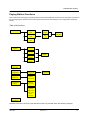
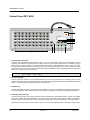
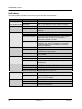
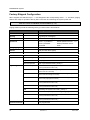
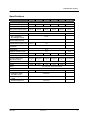
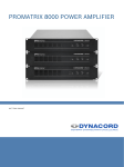
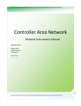
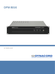
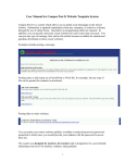
OWNER’S MANUAL
PROMATRIX paging stations DPC 4000
1
2
3
4
5
6
7
8
9
10
ALARM
11
12
13
14
15
16
17
18
19
20
DPC 4550
21
22
23
24
25
26
27
28
29
30
31
32
33
34
35
36
37
38
39
40
41
42
43
44
45
46
47
48
49
50
L ÖSCHEN
EIN
STO PP
ESC
ALL E
GO NG
PROG RAMM
BUSY
TEXT
SPRECHEN
PROMATRIX System
CONTENTS
CONTENTS
18
SYSTEM OVERVIEW
20
PAGING STATION FUNCTIONS
21
CONTROL PANEL DPC 4550
22
CONNECTIONS
24
KEY LABELING
24
OPERATION
25
Selective Call
25
Collective Call
25
Direct Call
25
Gong Signal
25
Text Message
26
General Alarm
26
Selective Alarm
26
Canceling Signals
26
System ON / OFF
27
Program Routing
27
Special Functions
27
INDICATORS
28
PRIORITIES
29
DPC 4350 PAGING STATION EXTENSION
29
FACTORY SETTINGS
30
SPECIFICATIONS
31
WARRANTY
48
18
Revision 1.1
DPC 4000
PROMATRIX System
DPC 4000
Revision 1.1
19
PROMATRIX System
System Overview
The PROMATRIX system includes 5 different paging station models and one paging station extension of the DPC
4000 - series. All paging stations employ gooseneck-microphones, 6 or respectively 8 function keys, and a covered
alarm key. An additional key as well as a key-lock switch can be retrofitted. All paging stations are available with 10,
20, 30, or 50 selection keys. All models come with LC-display (2 lines with 16 characters each).
The individual models are listed in the following table:
DPC 4106
DPC 4510
DPC 4520
DPC 4530
DPC 4550
DPC 4350
6 function keys
8 function keys + 10 selection keys + alarm key
8 function keys + 20 selection keys + alarm key
8 function keys + 30 selection keys + alarm key
8 function keys + 50 selection keys + alarm key
paging station extension with 50 selection keys
The paging stations employ the following common features:
•
all functions are processor-controlled
•
non-volatile configuration data FLASH-memory
•
condenser microphone incl. pre-amplifier and compressor / limiter
•
freely programmable key-assignment
•
easy labeling the keys via label-strips and MS WORD templates
•
monitoring of the analog circuitry via integrated pilot-tone oscillator
•
monitoring of the processor system via watchdog-circuit
•
line-monitoring via pilot-tone and polling
•
covered alarm key (except at the DPC 4106)
•
prepared for retrofitting additional alarm keys or key-lock switches
•
prepared for the connection of an external PTT-type microphone or audio signal source
•
piezo-humming device for acoustic alerts
•
prepared for the installation of an optionally available loudspeaker
•
set-up mode allows altering parameter settings directly at the paging station
•
two-line LC-display
All paging stations are processor-controlled and provide several monitoring functions. The integrated watchdogcircuitry monitors the processor system while the audio section is guarded by the signal of a switchable pilot tone
oscillator. Additionally, the internal supply voltage is constantly measured. Once it drops below a critical threshold, a
warning signal is being transmitted. Line-monitoring for the audio-cabling as well as for all RS-485 control-lines allows
the early recognition and signaling of line-interrupts and short-circuits.
Easy and comfortable configuration of the paging stations is accomplished through the use of the PROMATRIX
Designer software. The graphical, dialog-oriented user-interface allows setting all key-functions, priorities, options,
and several other parameters.
Note:
20
Up to four paging stations can be connected to a single input of the central unit. However, it is
important to keep the fact in mind that in case of line interruption or short-circuit several
microphone terminals can fail at the same time. Despite, inputs allow only launching one message
at a time. All other connected paging stations are presented with a busy-message. If these
restrictions are not acceptable, every microphone terminal - or at least all directing stations and
other important paging stations - should have their own input at the central unit.
Revision 1.1
DPC 4000
PROMATRIX System
Paging Station Functions
Next to elementary messaging, the paging stations offer several additional functions that in summation are shown in
the following diagram. Which functions a microphone terminal can initiate depend on its configuration and priority
setting.
Table of all functions
announcement
selective
call
lines
groups
collective
call
all
clear
selection
direkt
call
start
signal
gong
text
general
alarm
stop
signal
selective
alarm
power
on / off
program
assignment
lines
groups, all
special
functions
start
macro
instruction
paging station
setup
address
password
clear
assignment
Pre-gong
buzzer
compressor
date / time
LCDcontrast
service
functions
Detailed information concerning the different functions is provided within the following chapters.
DPC 4000
Revision 1.1
21
PROMATRIX System
Control Panel DPC 4550
11
12
1
2
3
4
5
6
7
8
9
10
11
12
13
14
15
16
17
18
19
20
AL AR M
10
DPC 4550
21
22
23
24
25
26
27
28
29
30
31
32
33
34
35
36
37
38
39
40
13
7
8
9
41
42
43
44
45
46
47
48
49
1
1
LÖSCHEN
EIN
STOPP
PROGRAMM
ALLE
GONG
TEXT
SPRECHEN
4
5
6
50
ESC
2
3
BUSY
Selection Keys with LED’s
Depending on the individual paging station model, 10, 20, 30, or 50 selection keys with corresponding LED’s are
provided. The selection keys are used to pre-select areas or groups for the reproduction of messages, gong or
alarm signals, vocal messages, or to assign programs (first press = ON, subsequent press = OFF). The LED’s
indicate the momentary selection status (also refer to the paragraph "indications"). It is also possible to assign
special functions or no function at all (no function assigned) to the selection keys. Assigning functions is performed
during the configuration procedure via PC.
Note:
2
When shipped, these keys are factory pre-set as area selection keys, where key 1 - area 1,
key 2 - area 2, ..., key n - area n.
ALL-key with LED
This key allows the selection of all programmed areas at once for the transmission of messages, gong or alarm
signals, vocal messages, or to assign programs. One time pressing selects all areas; the corresponding LED’s and
the ALL-LED are lit. Subsequent pressing cancels the selection.
3
CANCEL-key
This key has different functions, depending on the operation or mode, e.g. canceling the call-pattern or canceling a
program assignment. Which function is carried out at times is explained in detail in the paragraph OPERATION.
4
GONG-key (ESC) with LED
Pressing this key starts a gong signal, which is being transmitted into pre-selected areas or groups. The GONGLED is lit or blinks during the transmission of a gong signal. What kind of chime signal is being transmitted is
defined during the configuration procedure. Pressing the STOP-key cancels the reproduction of the gong signal.
While being in set-up mode, this key is used to return to 'normal' user mode (ESCAPE = leaving the set-up mode).
22
Revision 1.1
DPC 4000
PROMATRIX System
5
TEXT-key (∨
∨ ) with LED
Pressing this key starts a prerecorded message (optional voice reproduction) which is transmitted into the preselected areas or groups. The TEXT-LED is lit or blinks during the transmission of a prerecorded message. The
desired text message sequence is selected during the configuration procedure. Pressing the STOP-key cancels
the text message reproduction.
While being in set-up mode, pressing the TEXT-key decreases the selected parameter value (parameter entry).
6
TALK-button with BUSY-LED
This key activates a message for pre-selected areas or groups. While a message is being transmitted, the BUSYLED is lit. The TALK-button has to be pressed until the end of a message. The BUSY-LED blinks when one or
several areas are busy or when an event with higher priority setting interrupts the outgoing message (see
paragraph indications). In the latter case, it is necessary to repeat the message.
7
ON-key (<) with LED
This key turns the system's power on or off. Turning the power on can take several seconds. The ON-LED blinks
while the system boots. The ON-LED lights steadily when the system is operational. To prevent inadvertent
erroneous operation, it is necessary to press the key for at least 1 second when turning the power off. It is also
possible to 'block' the operation of the ON-key during the configuration procedure.
In set-up mode this key is used to select the previous parameter (parameter selection).
8
STOP-key (∧
∧)
Pressing the STOP-key cancels an outgoing alarm, gong signal, or text message. An alarm signal can also be
terminated by subsequently pressing the ALARM-key. Only events that were triggered from a specific paging
station can be stopped from the exact terminal with the exception of the directing station. This console allows
canceling all signals.
While being in set-up mode, this key increases the selected parameter value (parameter entry).
9
PROGRAM-key (>) with LED
Pressing the PROGRAM-key selects the program assign mode. The selection keys are used in this mode to
assign a program (background music) to the desired areas or groups. The PROGRAM-LED light when being in
program assign mode. In this case the selection-LED’s indicates in which areas / groups the program is being
transmitted.
Keeping this key pressed and simultaneously pressing the STOP-key selects the set-up mode and the
PROGRAM-LED starts blinking. Now you can alter preferences or make other changes as described in chapter
6.2.7 Paging Station Configuration in set-up mode.
When in set-up mode, this key is used to select the following parameter (parameter selection).
10 ALARM-key with indicator
Pressing the ALARM-key starts an alarm signal that is transmitted into all areas. The alarm indicator lights as soon
as the alarm is being launched. Pressing the STOP-key or subsequently pressing the ALARM-key terminates the
alarm signal. What kind of alarm signal is being transmitted is pre-defined during the configuration procedure of
the PROMATRIX system.
11 Optional key-slots
These slots allow retrofitting an additional covered key and a key-lock switch. The front panel is already prepared
for the installation of two 18 mm pushbuttons / switches. You only have to cut suitable holes into the front panel
cover-foil. Internal fittings are also already prepared. The newly installed switches' functions are assigned during
the configuration procedure via PC, e. g.: second alarm-pushbutton for transmitting alarm signals into specific
areas (selective alarm), or assigning the system ON / OFF function to the key-lock switch.
Detailed information and installation instructions are provided in the PROMATRIX user manual.
DPC 4000
Revision 1.1
23
PROMATRIX System
12 Microphone
By pressing the TALK-button and after the BUSY-LED lights, the integrated gooseneck microphone allows making
announcements in pre-selected areas or groups. The optimum distance from the microphone is approximately 8 to
12 inches. The microphone pre-amplifier embodies a limiter to control signal peaks and protect the system against
overdrive.
A second microphone with TALK-button can be connected to the extension socket (EXT). Assigning the function
(area, group) of the external microphone is performed during the configuration via PC.
13 Display
Depending on the system’s actual operational status, the LCD display with 2 lines and 16 characters, each
provides information on time, operation mode, user notes, setting up, fault messages including precise device /
module specification, etc.
Connections
1
LAN-socket
This is the connection interface for the DPC 4000 Series paging stations to the PROMATRIX system. The 8-pole
RJ-45 connector provides power supply, control interface RS-485 and audio connections. The microphone
terminal has to be connected to a corresponding wall outlet using the supplied connection cord (3 m).
2
EXT-socket
This socket is mostly used for connecting a DPC4350 paging station extension. Use the supplied network cable
(0.5 m) to connect the DPC4350 to the microphone terminal's EXT-socket.
Additionally, when no paging station extension is connected, it is possible to utilize the EXT-socket to connect a
second microphone with TALK-button or other external audio signal sources to the paging station. Detailed
information is provided in chapter 6.2.13 Optionally Available Accessories.
Key-Labeling
Labeling the keys on the paging stations is done via label-strips, which can be inserted from the side. The label-strips
for the 6 respectively 8 function keys are slit in from the right while the selection key strips – for 10, 20, 30, or 50
selection keys – are inserted from the left. Therefore, you have to detach the corresponding side panel (2 screws) and
insert the labeled strip into the guiding rail between the front panel and the front panel foil.
The most convenient way of printing the labels is to utilize the word processing software MS-WORD. A suitable MSWORD template is supplied. Please note that with different printers, margin-settings can vary making it necessary to
adjust the template according to the specifications of your printer.
Tested printers are:
HP LaserJet 6P
HP LaserJet 5
HP LaserJet II
The recommended paper thickness is between 120 g/m2 and 200 g/m2.
Also supplied with this handbook are prepared label-strips in German, English and French as well as blank strips,
which only have to be cut out. You can label the empty strips in handwriting or by using adhesive, rub-on letters.
24
Revision 1.1
DPC 4000
PROMATRIX System
Operation
This chapter explains all functions that are available in general operation mode.
Selective Call
The user can launch calls or announcements into freely selectable areas or groups.
Pressing a single or several selection keys defines the areas or groups that a call is launched into. The individual
corresponding LED’s will light. By pressing the key of an already pre-selected line once again deactivates that line
and the corresponding LED goes out.
After you have made your selection, pressing the TALK-button ignites the actual call. Prior to that you can check via
the BUSY-LED whether all lines and the paging station input are actually free. If single lines or the terminal input are
busy with lower priority transmissions, the BUSY-LED will blink slowly. Whilst announcements are possible, they will
interrupt any other event that is momentarily transmitted. If single lines or the terminal input are busy with higher
priority signals, the BUSY-LED will vastly blink and the calling attempt is being ignored (also refer to the description of
indicators).
The BUSY-LED lights during announcements. The TALK-button needs to be pressed during the whole message. After
releasing the TALK-button, the defined selection stays memorized until the user makes any changes. Pressing the
CANCEL-key de-selects the entire selection.
Additionally and in case of a pre-gong signal has previously been programmed, the GONG-LED will light during the
transmission of the pre-gong signal.
Collective Call
The announcement is launched into all areas of an installation.
The procedure is similar to making a selective call. First, pressing the ALL-key selects all areas of the installation.
Pressing the TALK-button activates the collective call. During the outgoing call all area and/or group LED’s as well as
the ALL-LED will light (also refer to "indications"). The TALK-button has to be kept pressed down until the end of an
announcement. BUSY-LED indication and the pre-gong signal behave equivalent to what was said for the selective
call.
Direct Call
Principally it is possible to assign a direct call to any selection key (area key, group key, ALL-key) during the PCconfiguration. This allows making announcements directly by pressing the desired selection key – without the need to
press the TALK-key first. For direct calls the BUSY-LED also signals the status of correspondent areas (free, busy
with lower priority signal, busy with higher priority signal; see "indications"). When shipped, there is no factory pre-set
direct call programmed.
Gong Signal
A gong signal can be transmitted into any selectable area or group of an installation.
First, the desired areas / groups have to be selected, either using the selection keys (selective gong) or with the ALLkey (general gong). Pressing the GONG-key releases the gong signal. While the gong signal is being transmitted, the
GONG-LED lights continuously or blinks (also refer to indications). The gong's priority can be set to 6 or 7. Therefore
it has priority over announcements from any paging station, except for the directing terminal (priority 10).
Pressing the STOP-key cancels the transmission of a gong signal.
DPC 4000
Revision 1.1
25
PROMATRIX System
Text Message
A text message recorded on the optional message module or on an external recording/playback device
can be transmitted into any selectable area or group of the entire installation.
First, the desired areas / groups have to be selected either using selection keys or with the ALL-key.
Pressing the TEXT-key starts the reproduction of a prerecorded message that had been assigned during
the configuration. While the text message is being transmitted, the TEXT-LED lights steadily or blinks
(also refer to indications). The priority for text messages can be set to values between 2 and 8.
Pressing the STOP-key cancels the transmission of a text message.
General Alarm
A general alarm signal is always transmitted to all lines of an installation.
Pressing the covered ALARM-key launches the integrated alarm. The key is lit during the transmission of
an alarm signal. The priority of the alarm can be set between 7 and 9 and therefore it has priority over any
announcement or other event, except for those that were ignited from the directing paging station
(priority 10).
Pressing the STOP-key or subsequently pressing the ALARM-key cancels the alarm.
Selective Alarm
When a paging station is equipped with a second ALARM-key, which provides the option for selective
alarms, it is possible to transmit alarm signals only into particular lines.
Equivalent to the procedure for making a selective call you first have to select the areas / groups to which
the alarm signal will be transmitted. Afterwards, you have to press the covered ALARM-key to start a
selective alarm. The key is lit during the transmission of an alarm signal. You can now already enter the
lines for the following alarm.
Pressing the STOP-key or subsequently pressing the ALARM-key cancels the alarm.
When shipped, there is no factory pre-set selective alarm pre-programmed.
Note:
Launching an alarm is not related to the originating paging station’s priority. Alarms can
be launched from any microphone terminal at any time, even when the system is in
stand-by mode. A running alarm is optically and occasionally also acoustically indicated
at each and every paging station.
Canceling Signals
Pressing the STOP-key cancels alarms, gong signals and text message transmissions. Events can only
be terminated at the paging station they were launched from with the exception of the directing terminal
(paging station with the highest possible priority-setting 10). Through the directing station it is possible to
cancel any signal in progress.
26
Revision 1.1
DPC 4000
PROMATRIX System
System ON / OFF
The ON-key switches a PROMATRIX system ON or OFF. Mostly, it is not intended that all paging stations
provide this option. Thus, this function can be individually programmed for each console via PCconfiguration.
With the system being in stand-by mode, the ON-LED is off. Pressing the ON-key turns the PROMATRIX
system's power on. This can take up to 10 seconds during which the ON-LED blinks. The ON-LED lights
constantly once the system is ready for operation. This also applies for all paging stations of the entire
installation
To switch the system OFF, you have to press the ON-key for approximately 1 second. This feature is
provided to prevent inadvertently turning off the system.
Pressing an ALARM-key or igniting an alarm sequence at external terminals automatically switches the
PROMATRIX system's power on and boots the system.
Program Assignment
In case this feature has been activated, it is possible to assign programs to individual areas and groups of
an entire installation during the PC-configuration procedure.
First, by pressing the PROGRAM-key, the paging station has to be set to the program-assign mode.
Pressing a single or several selection keys assigns the outputted program (background music) to selected
areas and groups. The corresponding LED’s are lit. Program transmission has always the lowest priority
(1). The level of the audio signal is determined during the PC-configuration procedure. The assignment
stays memorized until the selection keys are pressed again. Pressing the CANCEL-key erases the entire
assignment-pattern.
Subsequently pressing the PROGRAM-key or any other function key cancels the program-assign mode. It
is also automatically canceled after approximately 15 seconds.
In single-program configuration the music reproduction in all areas of the installation needs to be
attenuated for the time of an announcement. In double-program configuration it is possible to transmit the
background music program into rooms that are not part of an actual announcement selection. If every line
incorporates its own LF-output and separate power amplifier, it is possible to freely mix announcements
and background programs.
Special Functions
Generally, it is possible to assign a function to each selection key. This allows to utilize a paging station to
control the lighting, door openers, blinds, etc.; even controlling volume settings is possible through the use
of the UP / DOWN keys.
How to program and assign special functions is explained in detail in PROMATRIX user manual. When
factory-shipped, there are no special functions assigned.
DPC 4000
Revision 1.1
27
PROMATRIX System
Indications
The following table provides an overview of the most important LED-indications.
LED
Status
Description
selection-LED
OFF
area or group not selected
(not for DPC 4106) lights green
area or group selected / special function activated /
direct call activated
ALL-LED
collective call not selected
collective call pre-selected / direct collective call
activated
BUSY-LED
OFF
system not busy, clear for call
lights green
during own message
green, slowly blinking
low priority paging station launches a call in selected
areas; interruption on cost of the momentary
microphone terminal is possible
green, vastly blinking
system is busy with a higher priority transmission
(message, gong, alarm), interruption is not possible,
already launched call is interrupted by events with
higher priority setting
OFF
no gong signal started
lights green
gong signal in progress; manually started or preprogrammed pre-gong signal
green blinking
gong signal in progress, ignited from another source or
time-controlled
OFF
system is OFF (stand-by mode)
lights green
system is ON and ready for operation
green blinking
system has been turned on and is booting
(initialization)
OFF
paging station is in message-mode
lights green
paging station is in program-assign mode
green, slowly blinking
paging station is password-protected
green, vastly blinking
paging station is in setup mode
OFF
no text message launched
lights green
manually launched text message is in progress
green blinking
text message in progress, launched from another
source or time-controlled
OFF
alarm signal not launched
lights red
alarm signal has been launched from any source
red blinking
alarm signal has already been stopped, but keeps
running until signal-end
GONG-LED
ON-LED
PROGRAM-LED
TEXT LED
ALARM
28
OFF
(not for DPC 4106) lights green
Revision 1.1
DPC 4000
PROMATRIX System
Priorities
The PROMATRIX system allows setting 10 priority levels (highest priority = 10, lowest priority = 1) that
include announcements as well as alarm and gong signals and vocal message reproduction. A higher
prioritized event principally interrupts any other event with a lower priority setting. For events with equal
priority the earlier launched signal is continued – it has priority over the latter.
Priority level
10
7-9
6-7
2-8
2-6
1
Assigned to
directing station
Description
highest priority; can ignite any type of events and
interrupt all other signals
alarm signal
can only be interrupted from the directing station but
interrupts all other signals that have not been
launched from the directing terminal
gong signal
interrupts all signals that are not coming from the
(manual / time-controlled) directing terminal. Time-controlled gong signals can
be delayed/pre-delayed by a pre-defined period of
time
recorded message
text messages can be freely assigned to these
priorities during the configuration procedure
message from a paging these priorities can be freely assigned to any 'normal'
station without / with pre- paging station. A pre-gong signal has the priority of
gong signal
the launching microphone terminal
program
background music always has the lowest priority level
DPC 4350 paging Station Extension
The DPC 4350 paging station extension provides selection keys only. It is employed whenever more than
50 loudspeaker lines need to be accessed or whenever additional group and special function keys are
required. The DPC 4350 can be easily combined with any other paging station model. The following list
shows the amounts of maximally accessible lines for various combinations:
DPC
DPC
DPC
DPC
DPC
combination
4106 + DPC 4350
4510 + DPC 4350
4520 + DPC 4350
4530 + DPC 4350
4550 + DPC 4350
max. number of lines
50
60
70
80
100
The extension is directly connected to the main paging station’s extension interface (EXT) using the
supplied 8-pole RJ-45 cable. Consequently, a paging station consists of two devices, but reports to a
common address. Therefore the central unit recognizes such a combination as a single console with a
higher number of selection keys. From the view point of the user, the two devices also act as only one
paging station; i. e. the selection keys of main and slave paging stations provide equal access to their
assigned areas, groups and special functions.
DPC 4000
Revision 1.1
29
PROMATRIX System
Factory-Shipped Configuration
When shipped, the selection keys 1 – n are assigned to the corresponding areas 1 – n. Therefore, paging
stations are ready for operation directly after connection and switching the system power ON.
CAUTION:
If several paging stations are operated within an installation, it is extremely important that
each one is set to an individual, exclusive address (1 - 16).
Paging stations provide the following factory pre-set functions and features:
Parameter
Setting / Description
address
OFF
priority
5 (priority for messages)
name
untitled DPC4xxx (type)
password
level 1 no protection
level 2 passwordprotected
pre-gong signal
OFF
buzzer
ON (acoustic alert signal)
compressor
OFF
default password level 1: 111
default password level 2:
2222
extension socket
EXT
OFF
options
2nd alarm key
not programmed
key-locked switch
not programmed
PTT-microphone
call in pre-selected areas, priority 5
selection keys 1 – n
area selection 1 – n (key 1 area 1, key 2 area 2, ..)
key-assignment
(not supported with the DPC 4106)
TALK
call in pre-selected areas, priority 5
(DPC 4106: call in all areas)
TEXT
text message in pre-selected areas; text 1, priority 2
(DPC 4106: text message in all areas)
GONG
4-stroke gong signal in pre-selected areas, priority 8
(DPC 4106: gong signal in all areas)
ALL
selecting collective call
(not supported with the DPC 4106)
CANCEL
cancel selection / call-pattern
(not supported with the DPC 4106)
ON
switching the system ON / OFF, priority 5
STOP
terminates any locally launched signal (gong, text, alarm)
PROGRAM
assigns a program to pre-selected areas
(not supported with the DPC 4106)
ALARM
DIN-alarm in all areas, priority 9
(not supported with the DPC 4106)
special functions
30
not programmed
Revision 1.1
DPC 4000
PROMATRIX System
Specifications
DPC 4106
operation voltage
power consumption (24 V)
DPC 4510
DPC 4530
DPC 4550
DPC 4350
90 mA
90 mA
90 mA
120 mA
135 mA
95 mA
24 V DC (21,6 V – 31,2 V)
80 mA
80 mA
min. operation voltage
max. power consump. (15 V)
DPC 4520
85 mA
15 V DC
120 mA
120 mA
120 mA
LF – input extern
Line (default)
PTT – microphone
(A & B bridges closed)
-52 dBu
LF-output
(electronically balanced)
+6 dBu
sealable alarm-key with cover
optional
yes
connections
RJ-45
supplied connection cords
-
3m
0,5 m
-
5 ... 40° C
170x160x6
5
225x160x6
5
gooseneck
weight
-
2 x 16 digits 2 x 16 digits 2 x 16 digits 2 x 16 digits 2 x 16 digits
environmental temperature
enclosure dimensions
(W x D x H, in mm)
-
Yes
DPC 4350 extension
connection
LC-display
-
0 dBu
270x160x6
5
320x160x6
5
405x160x6
5
-
8 x 200 mm
1,0 kg
finish
1,5 kg
1,7 kg
335x160x65
1,8 kg
2,5 kg
1,9 kg
gray-white RAL 9002, micro-structure
accessories
monitor loudspeaker
-
NRS 90209
pushbutton / switch
selectable, 18 mm
NRS 90230
key-lock switch
18 mm
NRS 90231
transformer balanced
NRS 90232
DPC 4000
Revision 1.1
-
31