1
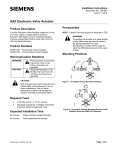
Installation Instructions
Document No. 129-540
July 29, 2013
SSD Series Electronic Valve Actuator
(For use with 1/2-Inch to 1-1/4-inch Pressure Independent Control Valves)
Product Description
Prerequisites
The SSD Actuator requires a 24 Volt power supply and
a 0 to 10 Vdc or floating control signal to control the
1/2-inch to 1-1/4-inch Siemens 599 Series Pressure
Independent Control Valves with a 1/10-inch (2.5 mm)
or 7/32-inch (5 mm) stroke.
Figure 1. Acceptable Mounting Positions.
NOTE: Vertical mounting position recommended.
Contents
90°
90°
SSD61U, SSD81U:
One actuator
•
One terminal plug
•
EA1261R1
•
One terminal connector
SSD61.5U, SSD81.5U:
One actuator
Figure 2. Acceptable Mounting Position with Valve.
Product Numbers
NOTE: Vertical mounting is recommended.
Product
Number
Description
Actuator
Code
SSD61U
0 to 10 Vdc control, NSR
231
SSD81U
Floating control, NSR
230
SSD61.5U
0 to 10Vdc control, SR
233
SSD81.5U
Floating control, SR
232
Warning/Caution Notations
WARNING:
CAUTION:
Personal injury/loss of life
may occur if you do not follow
a procedure as specified.
Equipment damage may
occur if you do not follow a
procedure as specified.
Required Tools
•
3 mm hex wrench
•
Small flat-blade screwdriver
•
Small, Phillips screwdriver
•
Wire stripper
Expected Installation Time
20 minutes
G¾
•
WARNINGS:
• If mounting the actuator to a valve
already in line, either close the shut-off
valves in the piping (upstream first,
then downstream), or switch off the
pump to allow the differential pressure
in the valve to drop.
• Disconnect the controller power before
replacing the actuator. See Removing
an SSD61.5U/SSD81.5U Actuator
from a Valve.
CAUTION:
• Before applying power, make certain a
valve is connected to the actuator.
• If applying power to the actuator when
a valve is not connected, the actuator
will respond to a control signal and the
shaft will extend until it reaches its
maximum end stop. Thereafter, it will
not respond to any signal.
• If this occurs, disconnect the power.
Insert a 3mm hex wrench into the
manual override feature and retract
the actuator to the zero position. Verify
the actuator shaft is retracted
completely. See Figure 14.
• Connect a valve to the actuator,
reapply the power, and the actuator
will return to normal operation.
Item No: 129-540, Rev CA
Page 1 of 6
Installation Instructions
Document No. 129-540
July 29, 2013
Installation
Mounting an SSD61U/SSD81U Actuator on
a Valve
1. Remove the protective plastic cap from the
valve. See Figure 3.
Figure 6. Tighten the Screw.
7. Place the actuator on the valve and firmly
hand-tighten the coupling clockwise.
See Figure 7.
Figure 3. Remove Plastic Cap.
2. Using a 3 mm hex wrench, turn the manualposition indicator on the top of the actuator
to "0".
3. Attach the wires to the terminal plug.
(Reference Wiring, See Figure 8 and Figure 11.)
4. Insert the terminal plug into the terminal
connector. See Figure 4.
Figure 7. Hand-Tighten Clockwise.
NOTE: Be sure the visual position indicator is
at the “0”position.
Installation is complete.
Mounting an SSD61.5U/SSD81.5U
Actuator on a Valve
1.
EA0594R1
2.
If you are attaching the actuator to a new valve,
remove the protective plastic cap from the valve
stem.
Use a 3mm hex wrench to retract the actuator to
the 0 position (Figure 14).
3.
Figure 4. Terminal Plug and Terminal Connector.
5. Place the terminal connector and plug into the
actuator, fitting the nut into the recess in the
bottom of the actuator. See Figure 5.
Using a Phillips head screwdriver, remove the
terminal cover (Figure 16).
4. Remove wiring retention screw.
5. Remove plenum cable adapter.
6. For plenum applications, complete wiring as
follows:
a. Route cable through plenum cable adapter so
b.
TERMINAL
PLUG
NOTE: Insert wiring retention screw in hole of the
flex conduit adapter. (The hole nearest
the wiring terminals is to secure the
terminal cover in place.)
EA1273R1
TERMINAL
CONNECTOR
Figure 5. Insert Terminal Connector.
7.
6. Tighten the screw to hold the connector in
place. See Figure 6.
Page 2 of 6
there is sufficient cable to complete wiring
terminations.
Insert plenum cable adapter into flex conduit
adapter and secure in place with wiring retention
screw.
c. Continue with Step 8.
For 3/8-inch flex conduit applications, complete
wiring as follows:
a. Discard plenum cable adapter.
Siemens Industry, Inc.
Document No. 129-540
Installation Instructions
July 29, 2013
b.
c.
Insert flex conduit into flex conduit adapter and
secure in place with wiring retention screw.
NOTE:
Insert wiring retention screw in hole of
the flex conduit adapter. (The hole
nearest the wiring terminals is to
secure the terminal cover in place.)
Route wiring through flex conduit for wiring
terminations.
G
Y1
Y2
24 Vac Operating Voltage
Output shaft extends, valve opens
Output shaft retracts, valve closes
SSD81.5U
CONTROLLER
8.
ACTUATOR
Y2
Y1
G
G0
24 Vac
G, G0:
24 Vac Operating voltage
0 Y2: Retracts actuator shaft
1 Y1: Extends actuator shaft
0 G: System neutral
G0: System potential
(switched)
NEUT
EARTH GROUND
ISOLATING CLASS 2
24 Vac TRANSFORMER
EA1235R1
Connect wires to wiring terminals per the Wiring
section of this document.
9. Secure the terminal cover in place over the wiring
terminals (Figure 16) using a Phillips head
screwdriver,
10. Place the actuator on the valve and firmly handtighten Figure 7.
CAUTION:
Hand-tighten the actuator to the valve.
The use of tools to tighten the assembly
together will cause damage.
Table 1. SSD81U Terminal Designations.
120 Vac
Figure 9. SSD81.5U Floating Control SR
Hot-Switch.
The installation is complete.
Wiring
•
All wiring must conform to NEC and local codes
and regulations.
•
Use earth ground isolating step-down Class 2
transformers.
•
Do not use autotransformers.
•
Determine the supply transformer rating by
summing the total VA of all actuators used.
•
CAUTION:
Terminals must be properly wired for
correct function and full life of the
actuator.
CONTROLLER
ACTUATOR
Y2
Y1
G
The maximum rating for a Class 2 step-down
transformer is 100 VA.
G0
•
CONTROLLER
ACTUATOR
Y2
Y1
0
1
G
NEUT
24 Vac
24
Vac
NEUT
EARTH GROUND
ISOLATING CLASS 2
24 Vac TRANSFORMER
EA1234R1
It is recommended that one transformer power no
more than 10 actuators.
SSD81U
G, G0:
24 Vac Operating voltage
0 Y2: Retracts actuator shaft
1 Y1: Extends actuator shaft
0 G: System potential
G0: System neutral
(switched)
120 Vac
Figure 10. SSD81.5U Floating Control SR Neutral
Switching Applications.
NOTE:
For proper operation, it is recommended no
more than three actuators be assigned to
any single control signal.
EA0795R1
EARTH GROUND
ISOLATING CLASS 2
TRANSFORMER FOR
24 Vac POWER
120 Vac
Figure 8. SSD81U Wiring Diagram.
Siemens Industry, Inc.
Page 3 of 6
Installation Instructions
Document No. 129-540
July 29, 2013
Calibration Stroke
SSD61U/SSD61.5U
+
Y
-
G0
G
NEUT
24
Vac
EARTH GROUND
ISOLATING CLASS 2
TRANSFORMER FOR
24 Vac POWER
1.
2.
A0-V BOARD
EA0069R3
The SSD61.5U writes its calibration stroke parameters
to non-volatile memory on the first start-up of the
actuator. Successive start-ups bypass the calibration
stroke unless the memory is manually cleared. If
installing the actuator on a different valve (such as on
a replacement valve), manually clear the calibration
stroke from memory as follows:
120 Vac
3.
Figure 11. SSD61U/SSD61.5U Wiring Diagram.
Table 2. SSD61U Terminal Designations.
G,G0
G
G0
Y
24 Vac operating voltage
System potential, 24 Vac
System neutral
0 to 10 Vdc control signal
4.
Remove the terminal cover using a Phillips head
screwdriver.
Locate hole on the circuit board with the shorting
bars. See Figure 13.
With power applied to the unit, insert and gently
twist a flat-blade screwdriver to electrically
connect the shorting bars. The SSD61.5U then
performs a new calibration stroke.
Secure the terminal cover back in place.
WARNING:
On the SSD61U/SSD61.5U the wire
connection G is 24 Vac, system potential
(HOT), not System neutral (ground).
CAUTION:
G0 and G must be properly wired for the
correct function and full life of the actuator.
Start Up
Check the wiring and the position indication. See
Figure 12 for referred positions “0”and “1” on the
position indicator.
• When the position indicator disc rotates to
position "1", the output shaft is extended.
• When the position indicator disc is at the "0"
position the output shaft is retracted.
Note:
The "0" and "1"
position markings
are intended for
reference only and
not for stroke
measurement.
Position 1
Position 0
Figure 12. Visual Position Indication.
Page 4 of 6
Figure 13. Manually Clearing Calibration Stroke from
SSD61.5U Non-volatile Memory.
Manual Override
A 3 mm hex wrench can be used to move the actuator
to any position between 0 and 1.
NOTE: A control signal from the controller takes
priority in determining the position.
To retain the manually set position, unplug the
connecting cable or switch off power and the
control signal.
CAUTION:
SSD61U/SSD61.5U: If an override is
performed while the power supply is
connected, the actuator will not track
accurately when the control signal is
applied. A short power off/power on
sequence is required to recalibrate the
actuator.
Siemens Industry, Inc.
Document No. 129-540
Installation Instructions
July 29, 2013
Turn the wrench clockwise to extend the actuator
shaft (counterclockwise to retract).
The actuator will maintain its position until power
is provided or restored.
3 mm
A
B
NOTE: Valve goes to closed position.
Removing an SSD61.5U/SSD81.5U
Actuator from a Valve
1.
2.
3.
4.
Remove the terminal cover (Figure 16) using a
Phillips head screwdriver.
Identify and disconnect wiring from the terminals.
Remove wiring retention screw.
Do one of the following:
•
•
EA0587R1
5.
•
B
A
6.
Remove plenum cable adapter and plenum cable;
or
Remove flex conduit.
Loosen the actuator coupling on the valve (Figure
7, reverse #2).
Remove the actuator from the valve.
(A) Turn hex wrench counterclockwise to
retract the shaft.
• (B) Turn hex wrench clockwise to extend the
shaft.
Figure 14. Manual Override.
Removing an SSD61U/SSD81U Actuator
from a Valve
1. Loosen the terminal connector with a flat-blade
screwdriver.
2. Remove the terminal connector and the terminal
plug from the actuator.
Figure 16. SSD61.5U/SSD81.5U Actuator Components.
Troubleshooting
•
Check the wiring for the proper connections.
•
If actuator becomes inoperable, replace the unit.
References
Figure 15. Removing Terminal Plug.
Technical Instructions
Document Number
3. Remove the terminal plug from the connector and
save.
SSD Series Electronic Valve Actuator
155-773
4. Loosen the actuator coupling, turn
counterclockwise.
Pressure Independent Control Series
2-Way, Brass Valve Bodies, 1/2-inch
to 2-inch, ANSI 250
155-774
5. Remove the actuator from the valve.
Siemens Industry, Inc.
Page 5 of 6
Installation Instructions
Document No. 129-540
July 29, 2013
Dimensions
2-7/8
(73)
EA1207R1
3-1/4
(82)
1-7/8
(48)
3-1/4
(83)
Figure 17. SSD61U/SSD81U Actuator in Inches (Millimeters).
Dimensions
Service
Envelope
Minimum access space
recommended:
1. 8 inches (200 mm)
above the actuator.
2. 8 inches (200 mm)
beside the terminal
cover.
Figure 18. SSD61.5U/SSD81.5U Actuator Dimensions in Inches (Millimeters).
Information in this publication is based on current specifications. The company reserves the right to make changes in specifications and models as
design improvements are introduced. Product or company names mentioned herein may be the trademarks of their respective owners. © 2013 Siemens
Industry, Inc.
Siemens Industry, Inc.
Building Technologies Division
1000 Deerfield Parkway
Buffalo Grove, IL 60089
USA
+ 1 847-215-1000
Your feedback is important to us. If you have
comments about this document, please send them
to [email protected]
Document No. 129-540
Printed in the USA
Page 6 of 6