1
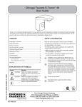
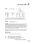
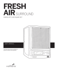
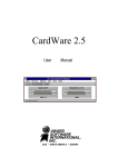
EQ Series User Guide Installation Instructions
For single supply and dual supply EQ Series faucets
Overview
Chicago Faucets EQ Series faucets feature three designs in two finishes with heavy-duty cast brass spouts and high-quality electronic components. The
faucet is up and running in minutes without the need for programming. Superior user detection means EQ turns on when user approaches and shuts off
when user leaves. It also adjusts for optimal performance, saving water.
Safety Information
Read this entire user guide to ensure proper installation. Compliance and conformity to local codes and ordinances is the responsibility of the installer.
The following safety notes must always be complied with during handling of this product:
• Make sure there is enough space and lighting available during installation and service.
• Do not modify or convert this Chicago Faucets product yourself. All warranties will be voided.
EQ Angular
Notice to the Installer
• Read this entire instruction sheet before installing to ensure proper installation.
• Installation must comply with local codes and ordinances.
• Do not use pipe dope.
• Care shall be exercised when installing the device to prevent marring the exposed, decorative surfaces.
The supply piping to these devices shall be securely anchored to the building structure to
prevent installed device from unnecessary movement when operated by the user.
NOTE: The information in this manual is subject to change without notice.
Operating static pressure: 20-125 PSI (138-862 kPa)
Minimum static pressure for mixing: 30 PSI (207 kPa)
COLD water inlet temperature range: 40-80°F (4-27°C)
HOT water inlet temperature range: 100-180°F (38-82°C)
Maximum hot water range outlet from thermostatic
mixing valve: 80-120°F (27-49°C)
Maximum hot water range outlet from mechanical mixing
valve: 40-140°F (4-60°C)
Maximum pressure differential between Hot & Cold water
supplies: 20%;
Maximum inlet water supply temperature differential:
20°F (9°C)
Installation may be performed at different times of construction by different individuals.
For this reason, these instructions should be left on-site with the facility or maintenance
manager.
NOTE: Before installation, turn off water supplies to existing faucet and remove faucet if
replacing. Clean faucet basin and clear away debris. Flush all supply lines before
connecting to faucet. Failure to do so can result in debris clogging the inlets and/or
internal control and mixing valves.
In order to complete the installation, you will need the following tools and supplies:
• Phillips Screwdriver, #1, #2, #3
• Drill, with 3/16˝ Bit
• Adjustable Wrench
• Mallet
• Tape Measure
• Plumbers Putty
• Silicone-based Lubricant
• 1/2˝ Deep Socket or #3 Flat Head Screwdriver
EQ Curved
EQ High Arc
Mounting of Faucet and Optional Cover Plate
1
1
2
2
1/2˝ Socket
1
2
1. Install the gasket on the bottom
of the spout, flat side down. If
installing a cover plate, align the
holes in the spout base with the
pins on the plate, and feed the
power cable and braided hose
through the plate. Secure the
plate to the spout with the #3
Phillips screw.
2. A
ttach the threaded rods to
the bottom of the cover plate.
Apply plumber’s putty to the
underside of the cover plate
where shown.
3. Position the faucet on the
sink. For all installations, handtighten the spout to the deck
with the large black spacer
and long mounting nut. For
installations with a cover plate,
also attach the large cup
washers, flat washers, and
wing nuts to the threaded rods.
4. When the spout is in the
desired position, use a wrench
to tighten all mounting
hardware.
Mounting Control Box
17-21˝
(43-53 cm)
3
1
1
2
1
screw
Remove
access
for box
2
1
2
24˝
(61 cm)
2
1.Remove the control box
cover by using a #2 Phillips
screwdriver to loosen the
cover screw.
2.Pivot the yellow locking tab and
remove the metal key at the
top of the control box. Apply
silicone-based lubricant to
the end of the spout hose and
insert it through the hole.
3. Be sure to seat the hose firmly
before reinstalling the metal key
and securing it with the yellow
locking tab.
4.Determine the position of the
control box under the sink.
Hold the control box against
the wall and mark the locations
of the two mounting holes.
Orientation is not critical.
5. Drill 3/16˝ holes, install wall
anchors and mounting screws.
Be sure to leave at least 1/2˝
(12mm) of the screw head
exposed. Secure the control
box to the wall using a #2
Phillips screwdriver.
Connecting Power and Solenoid
Connecting Water Supply (dual supply unit shown)
3
2
1
H
1.Insert the filter screen gaskets
into the supply stops.
IMPORTANT: the filter screen
gaskets seal the connection
against leaks and must be
installed as shown.
1
C
2. Attach the 3/8˝ female compression supply hoses from the
control box to the supply stops.
Use a wrench to tighten the
nuts to the supply stops.
3.Open the supply stops and
check for leaks. Note: water
may run through spout.
1.Bring wire into box. Use length
of box for measurement. Snap
into holder on side.
IMPORTANT: Remove any
debris or hardware from the sink
before opening the supplies and
testing the faucet.
For additional technical assistance, call 800/TEC-TRUE (800-832-8783) or visit our website at chicagofaucets.com.
2.Attach power connections
as shown in the following
sections.
EQ Series User Guide Installation Instructions
(continued)
Battery (DC) Power
Self Sustaining Power System (SSPS)
1
1
3
4
2
1
2
i. Open the yellow battery housing
and insert 4 ‘AA’ batteries according
to the diagram inside the housing.
NOTE: Make sure the batteries are
oriented properly before testing the
faucet.
3
2
#1 Phillips
ii. Attach the wiring connectors (gray
to gray, black to black). Note that
the connectors are keyed for proper
installation as shown in the detail below.
Snap the completed connections, into
the wiring harness as shown.
i. Insert the SSPS power supply into
the upper compartment of the control
box. Attach the wiring connectors,
first gray to gray, then black to black.
Note that the connectors are keyed
for proper installation as shown in the
detail below. Snap the completed
connections, into the wiring harness
as shown.
ii. Connect the blue connector on the
SSPS to the blue connector on the
turbine and tuck them into the cavity
as shown.
(AC) Power
3
1
2
1
QUICK TROUBLESHOOTING
Follow the steps below to fix common
problems. For detailed troubleshooting, visit
eqfaucets.com. Before troubleshooting,
remove any objects in detection zone
and make sure sensor is clear of debris.
Ensure power is applied and solid red
light appears during first 5 seconds after
power-up.
2
OR
120VAC,
60 Hz
120VAC,
60 Hz
i. Choose a location and mount the
transformer. Run the cable from the
transformer through the opening in
the control box.
ii. Attach the wiring connectors (gray
to gray, black to black). Note
that the connectors are keyed for
proper installation as shown in the
detail below. Snap the completed
connections into the wiring harness
as shown.
iii. Plug the transformer into
the wall.
iv. Wire up the
transformer to the
main line.
The faucet is leaking:
From outlet – tighten or replace outlet
insert using included key.
From supply stops – install or replace
filter screen gaskets (see diagram on
page 1).
No water flow or flow is limited:
Make sure supply hoses are connected
and supply stops are fully open. Clean
or replace filter screen gaskets or
outlet insert.
Completing Installation: Testing and Adjustment
Water flow does not stop:
If water flows continuously but stops
when hand enters detection zone,
reverse solenoid electrical connections.
2
Remove and reapply power or run faucet
to maximum run time. This will cause
automatic recalibration of sensing field.
Recalibration is complete when solid red
light disappears.
screw
Remove
access
for box
1
1.Once wiring is complete, the
red sensor light at the faucet
outlet will glow continuously
for 5 seconds. After the light
switches off, place your hands
in front of the faucet. The faucet
should activate and water
should flow from the spout.
2.Adjusting the Water Temperature
a.T
he yellow mixer handle inside
b. The mixed water temperature
the control box is used to
must be checked at the point of
adjust water temperature
use and the CFC mixing valve
in dual-supply installations.
adjusted to ensure delivery of
Turn the handle clockwise to
water at a safe temperature no
decrease water temperature or
exceeding 110°F (43°C). Water
counter-clockwise to increase
temperatures in excess 110°F
water temperature.
(43°C) are dangerous and may
cause scalding, severe injury or
death!
Faucet does not properly
detect user:
3. R
einstall the control box cover
and secure it with the #2
Phillips screw.
If the steps above do not solve the
problem, you may need to replace
the spout assembly or control box.
For additional information contact
Chicago Faucets’ customer service
at 800/832-3783.
WARNING!
Delivery of water to fixtures intended for hand washing is recommended to be controlled by valves listed to ASSE 1070. This fitting is NOT factory preset and can be adjusted to deliver water at temperatures exceeding 110°F (43°C).
Further, mechanical mixing valves DO NOT provide automatic control of water temperature. Due to effects of various water conditions, periodic verification of outlet water temperature is required.
Care and Maintenance
Periodic inspection and yearly maintenance by a licensed contractor is required for all thermostatic mixing elements. Corrosive water conditions and/or unauthorized adjustments or repair could
render the thermostatic valve ineffective for service intended. Regular checking and cleaning of the valve’s internal components and check stops helps assure maximum life and proper product
function. Frequency of cleaning and inspection depends on local water conditions. All Chicago Faucets fittings are designed and engineered to meet or exceed industry performance standards.
Care should be taken when cleaning this product. Do not use abrasive cleaners, chemicals, or solvents as they can result in surface damage. Use mild soap with warm water for cleaning and
protecting the surface of Chicago Faucets fittings.
For additional technical assistance, call 800/TEC-TRUE (800-832-8783) or visit our website at chicagofaucets.com.
CHICAGO FAUCETS LIMITED WARRANTY
TO WHOM DOES THIS WARRANTY APPLY? — The Company extends the following limited warranty to the original user only.
WHAT DOES THIS WARRANTY COVER AND HOW LONG DOES IT LAST?
This warranty covers the following Commercial Products:
LIFETIME FAUCET WARRANTY — The “Faucet,” defined as any metal cast, forged, stamped or formed portion of the Product, not including electronic or moving parts or other
products separately covered by this Limited Warranty or water restricting components or other components, is warranted against material manufacturing defects for the life of the Product.
FIVE YEAR FAUCET WARRANTY — Certain Products and portions of the Product are warranted against material manufacturing defects for a period of five (5) years from the date of Product purchase. Products warranted against material
manufacturing defects for a period of five (5) years from the date of Product purchase are referred to by the product numbers 42X, 43X, 15XX and E-Tronic® - 4X, 5X, 6X, 7X, 8X and 9X. All zinc die cast portions of Product are warranted against
material manufacturing defects for a period of five (5) years from the date of Product purchase.
THREE YEAR ELECTRONICS WARRANTY — Electronic components, including the solenoid, are warranted for three (3) years from the date of installation.
The Chicago Faucet Company
FIVE YEAR CARTRIDGE WARRANTY — The “Cartridge”, defined as the metal portion of any Product typically referred to by the product numbers containing 1-099, 1-100, 377X,
217X and 274X, excluding any rubber or plastic components, is warranted against material manufacturing defects for a period of five (5) years from the date of Product purchase.
2100 South Clearwater Drive
All Cartridges included in the Company’s Single Control or Shower Products also are warranted against material manufacturing defects for a period of five (5) years from the date of Product purchase.
Des Plaines, IL 60018
ONE YEAR FINISH WARRANTY – COMMERCIAL — For Products used in commercial applications, the finish of the Product is warranted against material manufacturing defects for a period
Phone: 847/803-5000
of one (1) year from the date of Product purchase.
Fax: 847/803-5454
OTHER WARRANTIES — All other Products not covered above are warranted against material manufacturing defects for a period of one (1) year from the date of Product purchase.
Technical: 800/832-8783
Other restrictions and limitations apply. For complete warranty details, call Chicago Faucets Customer Service at 847-803-5000 or visit chicagofaucets.com.
2
www.chicagofaucets.com
© 2014 Chicago Faucet Company 957.109.00.0 12/14