1
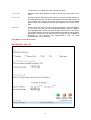
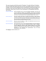
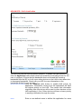
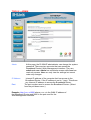
Contents Introduction............................................................................ 4 Package Contents.......................................................…..7 Hardwa re Description..............................…....………… 9 Reset...............................................…………………………....... 9 Getting Started .................................................................. 10 Using the Configuration Wizard...................…..... 11 Using the Configuration Menu............................... 12 HOME > WAN > DYNAMIC IP Address .............................................................................. 13 HOME > WAN > Static IP Address...................................................................................... 14 HOME > WAN > PPPOE ..................................................................................................... 15 HOME > WAN > Other>PPTP............................................................................................. 16 HOME > WAN > Other>L2TP.............................................................................................. 17 HOME > WAN > Other>BigPond Cable .............................................................................. 18 HOME > LAN ....................................................................................................................... 19 HOME > DHCP.................................................................................................................... 20 ADVANCED > VIRTUAL SERVER...................................................................................... 21 ADVANCED > APPLICATIONS .......................................................................................... 23 ADVANCED > FILTERS > IP FILTERS .............................................................................. 25 ADVANCED > FILTERS > MAC FILTERS.......................................................................... 26 ADVANCED > Parental Control > URL BLOCKING............................................................ 27 ADVANCED > Parental Control > DOMAIN BLOCKING .................................................... 28 ADVANCED >FIREWALL.................................................................................................... 29 ADVANCED > DMZ ............................................................................................................. 30 ADVANCED > DDNS........................................................................................................... 31 ADVANCED > QoS.............................................................................................................. 32 TOOLS > ADMIN ................................................................................................................. 39 TOOLS > TIME .................................................................................................................... 40 TOOLS > SYSTEM.............................................................................................................. 41 TOOLS > FIRMWARE......................................................................................................... 42 TOOLS > MISC.................................................................................................................... 43 TOOLS > Cable Test ........................................................................................................... 44 STATUS > DEVICE INFORMATION................................................................................... 45 STATUS > LOG ................................................................................................................... 46 STATUS > Statistics ............................................................................................................ 47 STATUS > Printer Info ......................................................................................................... 48 STATUS > Active Session................................................................................................... 49 2 Help...................................................................................................................................... 50 Technical Specifications............................................ 51 Appendix............................................................... 52 3 Introduction The D-Link DI-604UP is a 4-port Ethernet Broadband Router. It also comes equipped with one USB 1.1 port on the rear panel that supports printer sharing. The D-Link DI-604UP enables users to quickly and easily share a high speed Internet connection. It also incorporates many advanced features, traditionally found in more expensive routers. After completing the steps outlined in the Quick Installation Guide (included in your package) you will have the ability to share a single Internet connection as well as sharing information and resources such as files and printers. The DI-604UP is compatible with most popular operating systems, including Macintosh, Linux and Windows, and can be integrated into an existing network. This Manual is designed to help you connect the D-Link DI-604UP to a high speed Internet connection and 4 Ethernet PC connections. This manual provides a quick introduction to Broadband Router Technology, Firewalls, and Local Area Networking. Please take a moment to read through this manual and get acquainted these various technologies. Features and Benefits Broadband Modem and IP Sharing Connects multiple computers to a Broadband (Cable or DSL) modem to share the Internet connection. Ethernet Switch Allows you to quickly and easily share an Internet connection with multiple computers and devices. Built-In Print Server Includes a USB port to connect to a USB printer and includes a Windows -based print server software applications, so users on the network can share the printer. The print server is also capable of TCP/IP printing. VPN supported Supports multiple and concurrent IPSec and PPTP pass-through sessions, so multiple users behind the DI-604UP can access corporate networks through various VPN clients more securely. Advanced Firewall & Parental Control Features The Web-Based user interface displays a number of advanced network management features including: Content Filtering Easily applied content filtering based on Mac Address, IP Address, URL and/or Domain Name. 4 Filter Scheduling These filters can also be scheduled to be active on certain days or for a duration of hours or minutes. Network Address Translation NAT allows you to share a single IP Address and protects you from outside intruders gaining access to your private network. DHCP Server Supported All of the networked computers can retrieve TCP/IP settings automatically from the DI-604UP. Web-Based Management DI-604UP is configurable through any network computer’s web browser using Netscape or Internet Explorer. Access Control Supported Allows you to assign different access rights for different users. Virtual Server Supported Enables you to expose WWW, FTP and other services on your LAN to be accessible to Internet users. Special Application Supported Special applications requiring multiple connections, like Internet gaming, video conferencing, Internet telephony and so on. The DI-604UP can sense the application type and open a multi-port tunnel for it. DMZ Host Supported Allows a networked computer to be fully exposed to the Internet. This function is used when the Special Application feature is insufficient to allow an application to function correctly. Technology Introduction Introduction to Broadband Router Technology A router is a device that forwards data packets from a source to a destination. Routers forward data packets using IP addresses and not a MAC address. A router will forward data from the Internet to a particular computer on your LAN. The information that makes up the Internet gets moved around using routers. When you click on a link on a web page, you send a request to a server to show you the next page. The information that is sent and received from your computer is moved from your computer to the server using routers. A router also determines the best route that your information should follow to ensure that the information is delivered properly. A router controls the amount of data that is sent through your network by 5 eliminating information that should not be there. This provides security for the computers connected to your router, because computers from the outside cannot access or send information directly to any computer on your network. The router determines which computer the information should be forwarded to and sends it. If the information is not intended for any computer on your network, the data is discarded. This keeps any unwanted or harmful information from accessing or damaging your network. Introduction to Firewalls A firewall is a device that sits between your computer and the Internet that prevents unauthorized access to or from your network. A firewall can be a computer using firewall software or a special piece of hardware built specifically to act as a firewall. In most circumstances, a firewall is used to prevent unauthorized Internet users from accessing private networks or corporate LAN’s and Intranets. A firewall watches all of the information moving to and from your network and analyzes each piece of data. Each piece of data is checked against a set of criteria that the administrator configures. If any data does not meet the criteria, that data is blocked and discarded. If the data meets the criteria, the data is passed through. This method is called packet filtering. A firewall can also run specific security functions based on the type of application or type of port that is being used. For example, a firewall can be configured to work with an FTP or Telnet server. Or a firewall can be configured to work with specific UDP or TCP ports to allow certain applications or games to work properly over the Internet. Introduction to Local Area Networking Local Area Networking (LAN) is the term used when connecting several computers together over a small area such as a building or group of buildings. LAN’s can be connected over large areas. A collection of LAN’s connected over a large area is called a Wide Area Network (WAN). A LAN consists of multiple computers connected to each other. There are many types of media that can connect computers together. The most common media is CAT5 cable (UTP or STP twisted pair wire.) On the other hand, wireless networks do not use wires; instead they communicate over radio waves. Each computer must have a Network Interface Card (NIC), which communicates the data between computers. A NIC is usually a 10Mbps network card, or 10/100Mbps network card, or a wireless network card. Most networks use hardware devices such as hubs or switches that each cable can be connected to in order to continue the connection between computers. A hub simply takes any data arriving through each port and forwards the data to all other ports. A switch is more sophisticated, in that a switch can determine the destination port for a specific piece of data. A switch minimizes network traffic overhead and speeds up the communication over 6 a network. Networks take some time in order to plan and implement correctly. There are many ways to configure your network. You may want to take some time to determine the best network set-up for your needs. Package Contents DI-604UP Ethernet Broadband Router Power Adapter Ethernet Cable Quick Installation Guide Manual on CD Note: Using a power supply with a different voltage rating will damage and void the warranty for this product. If any of the above items are missing, please contact your reseller. 7 Hardware Description Front Panel WAN LED Status LED LAN LEDs Power LED Power USB LED A solid light indicates a valid connection to the power supply. WAN An active LED indicates a link has been established. A blinking LED indicates activity on the WAN port. LAN An active LED indicates a link has been established. A blinking LED indicates activity on the LAN port. Status A blinking LED indicates the DI-604UP is functioning properly. USB An active LED indicates a link has been established. A blinking LED indicates activity on the USB port 8 Hardware Description Rear Panel WAN Port Reset Button LAN Ports USB Port Power Adapter Reset Used to restore the DI-604UP back to factory default settings. LAN PORTS* 1-4 LAN port sockets (CAT5 Ethernet RJ-45 cable) . The LED glows steadily when a port is connected to a hub, switch or network -adapter-equipped computer in your local area network (LAN.) WAN* WAN port socket (CAT5 Ethernet RJ-45 cable). This is where you will connect your Cable or DSL modem. USB Port Connect to the printer using a USB cable. This feature is used to share the printer on the network. Power Connect one end of your included power adapter to the power port and the other end into your power outlet. *All ports (both LAN & WAN) are Auto-MDIX. All ports auto-sense cable types to accommodate Straight-through or Cross-over cable. Reset To reset the system settings to factory defaults, please follow these steps: 1. Leave the device powered on , do not disconnect the power 2. Press the reset button and hold (use a paper-clip) 3. Keep the button pressed about 5-6 seconds 4. Release the button The DI-604UP will then automatically reboot itself. 9 Getting Started Installation Location The DI-604UP can be positioned at any convenient place in your office or house. No special wiring or cooling requirements are needed. However, you should comply with the following guidelines: Place the DI-604UP on a flat horizontal plane. Keep away from any heating devices. Do not place in a dusty or wet environment. The recommended operational specifications of the DI-604UP are: Temperature 32℉ ~ 113℉ Humidity 10% ~ 95% In addition, remember to turn off the power, remove the power cord from the outlet, and keep your hands dry when you install the hardware. Network Settings To use the DI-604UP correctly, you have to properly configure the network settings of your computers. The default IP address of the DI-604UP is 192.168.0.1, and the default subnet mask is 255.255.255.0. These addresses can be changed as needed, but the default values are used in this manual. If the TCP/IP environment of your computer has not yet been configured, you can refer to Configuring Your PCs to Connect to the DI-604UP to configure it. For example: 1. Configure your computer IP as 192.168.0.3, subnet mask as 255.255.255.0 and gateway as 192.168.0.1 Or more conveniently 2. Configure your computers to obtain TCP/IP settings automatically from the DHCP server feature of the DI-604UP Since the IP address of the DI-604UP is 192.168.0.1, the IP address of your computer must be 192.168.0.X (where “X” is a number between 2 and 254.) Each computer on your network must have a different IP address within that range. The default gateway must be 192.168.0.1 (the IP address of the DI-604UP). 10 Using the Configuration Wizard The DI-604UP provides an embedded Web-based management utility making it operating system independent. You can configure your DI-604UP through the Netscape Communicator or Internet Explorer browser in MS Windows, Macintosh, Linux or UNIX based platforms. All that is needed is a web browser such as Internet Explorer or Netscape Navigator version 4 and higher with Java Script enabled. Start-up and Log in Activate your web browser and type in the IP address of the DI-604UP into the Location (for Netscape) or Address (for IE) field and press “Enter.” The default IP address of the DI-604UP is 192.168.0.1 Open your Web browser and type “http://192.168.0.1” into the URL address box. Then press the Enter or Return key. After the connection is established, the logon screen will pop up. To log in as an administrator, enter the username of “admin” and the password (there are no default password, leave it blank). Click the OK button. If the password is correct, the web-management interface will appear. Type “admin” for the username and leave the password field blank. Click OK 11 Clicking Apply will save configured settings to the router. Clicking Cancel will clear changes made to the current page. Clicking Help will provide the user with helpful information about the current window. Clicking Refresh will refresh the statistics of the current window. The Home > Wizard window will appear. Please refer to the Quick Installation Guide for more information regarding the Setup Wizard. These buttons appear on most of the configuration windows in this section. Please click on the appropriate button at the bottom of each window after you have made a configuration change. Note: if you have changed the default IP Address assigned to the DI-604UP, make sure to enter the correct IP Address. Using the Configuration Menu Setup Wizard The Setup Wizard page is the first page that appears when logging into the web-based management interface. The Setup Wizard is a utility used to quickly configure the DI-604UP. It will guide you through four quick and basic steps to help you connect to your ISP. You will be connected to your ISP (Internet Service Provider) and have Internet access within minutes. WAN WAN is short for Wide Area Network. The WAN settings can be referred to as the Public settings. All IP information in the WAN settings are public IP addresses which are accessible on the Internet. The WAN settings consist of three options: Dynamic IP Address, Static IP Address, PPPoE and Others(PPTP,L2TP,BigPond Cable and Multi-PPPoE). Select the appropriate option and fill in the information needed to connect to your ISP. 12 HOME > WAN > DYNAMIC IP Address Choose Dynamic IP Address to obtain IP address information automatically from your ISP. Select this option if your ISP does not give you any IP numbers to use. This option is commonly used for Cable modem services. Host Name The Host Name field is optional but may be required by some ISPs. The host name is the device name of the Broadband Router. MAC Address The default MAC address is set to the WAN's physical interface MAC address on the Broadband Router. You can use the "Clone MAC Address" button to copy the MAC address of the Ethernet Card installed by your ISP and replace the WAN MAC address with this MAC address. It is not recommended that you change the default MAC address unless required by your ISP. 13 HOME > WAN > Static IP Address Choose Static IP Address if all WAN IP information is provided to you by your ISP. You will need to enter in the IP address, subnet mask, gateway address, and DNS address(es) provided to you by your ISP. Each IP address entered in the fields must be in the appropriate IP form, which are four IP octets separated by a dot (x.x.x.x). The Router will not accept the IP address if it is not in this format. IP Address Public IP address provided by your ISP. Subnet Mask Subnet mask provided by your ISP. ISP Gateway Address Public IP address of your ISP that you are connecting to. Primary DNS Address Primary DNS (Domain Name Server) IP provided by your ISP Secondary DNS Address optional 14 HOME > WAN > PPPOE Please be sure to remove any existing PPPoE Client Software installed on your computers. Choose PPPoE (Point to Point Protocol over Ethernet) if you’re ISP uses PPPoE connection. Your ISP will provide you with a username and password. This option is typically used for DSL services. Select Dynamic PPPoE to obtain an IP address automatically for your PPPoE connection. Select Static PPPoE to use a static IP address for your PPPoE connection. Dynamic PPPoE PPPoE connection where you will receive an IP address automatically from your ISP Static PPPoE PPPoE connection where you have an assigned (static) IP Address User Name Your PPPoE username provided by your ISP Password Your PPPoE password provided by your ISP Retype Password Re-enter PPPoE password Service Name Enter the service name provided by your ISP. (optional) IP Address This option is only available for Static PPPoE. Enter in the static IP address for the PPPoE connection. Primary DNS Address Primary DNS IP provided by your ISP Secondary DNS Address optional Maximum Idle Time The amount of time of inactivity before disconnecting your PPPoE session. Enter a Maximum Idle Time (in minutes) to define a maximum period of time for which 15 the Internet connection is maintained during inactivity. If the connection is inactive for longer than the defined Maximum Idle Time, then the connection will be dropped. Either set this to zero or enable Auto-reconnect to disable this feature. MTU MTU stands for Maximum Transmission Unit. For PPPoE connections, you may need to change the MTU settings in order to work correctly with your ISP. Auto-Reconnect If enabled, the Broadband Router will automatically connect to your ISP after your system is restarted or if the connection is dropped. HOME > WAN > Other>PPTP PPTP or Point-to-Point Protocol is a safe method of sending information between VPN’s securely using encryption over PPP. You, as the client, need to enter the correct information that the server has in order to create that secure tunnel. Using Dynamic IP, the router will set your basic IP parameters for you, such as the IP Address, Subnet Mask and Gateway. For Static IP, this information must be set manually by the user. All information in this window should be provided by your ISP. PPTP Choose between Dynamic and Static IP. IP Address Enter the IP address of the router for a static IP entry. Dynamic IP requires no input here. Subnet Mask Enter the Subnet Mask address of the router for a static IP entry. Dynamic IP requires no input here. Gateway Enter the gateway address here. This is the IP address of the ISP server. Server IP Enter the IP address of the PPTP’s server computer. This is how the user will become authenticated to use PPTP. PPTP Account: Enter the name of the PPTP account as provided to you by your ISP. PPTP PasswordEnter the PPTP password as provided to you by your ISP. PPTP Retype Retype the password entered in the PPTP Password field. Password Maximum Idle Time A value of 0 means that the PPP connection will remain connected. If 16 your network account is billed according to the amount of time the Router is actually connected to the Internet, enter an appropriate Idle Time value (in seconds). This will disconnect the Router after the WAN connection has been idle for the amount of time specified. The default value = 5. MTU Enter an MTU value only if required by your ISP. Otherwise, leave it at the default setting. Connect Mode This function, with Connect-on-demand selected, will allow the router to connect any workstation on your LAN to the Internet upon request. If this function is set at Always-on, no request from the workstation will be needed to connect to the Internet. If Manual is selected, it will be necessary for the workstation on the LAN to manually connect to the Internet through this router. HOME > WAN > Other>L2TP Some ISPs may require the user to uplink using the Layer 2 Protocol Tunneling (L2PT) method. L2PT is a VPN protocol that will ensure a direct connection to the server using an authentication process that guarantees the data originated from the claimed sender and was not damaged or altered in transit. Once connected to the VPN tunnel, it seems to the user that the client computer is directly connected to the internal network. To set up your L2PT connection, enter the following data that was provided to you by your ISP. L2PT Choose between Dynamic and Static IP. Using Dynamic IP, the router will set your basic IP parameters, such as the IP Address, Subnet Mask and Gateway. For Static IP, this information must be set manually by the user. IP Address The IP address that will be assigned to your router for this connection, as stated by your ISP. Dynamic IP requires no input here. Subnet Mask The IP address of the corresponding Subnet Mask, as stated to you by your ISP. Dynamic IP requires no input here. Gateway The IP address of the gateway device, as stated to you by your ISP. Dynamic IP requires no input here. Server IP The IP address of your ISP’s server computer, as stated to you by your ISP. L2PT Account The account name of the L2PT account that has been assigned to you by your ISP. L2PT Password The password of the L2PT account that was supplied to you by your ISP. L2PT Retype Password Retype the password that was entered in the L2PT field. Ensure that these two passwords are identical or an error will occur. Maximum Idle Time A value of 0 means the PPP connection will remain connected. If your 17 network account is billed according to the amount of time the Router is actually connected to the Internet, enter an appropriate Idle Time value (in seconds). This will disconnect the Router after the WAN connection has been idle for the amount of time specified. The default value = 5. MTU Enter an MTU value only if required by your ISP. Otherwise, leave it at the default setting. Connect Mode If Connect-on-demand is selected, will allow the router to connect any workstation on your LAN to the Internet upon request. If Always-on, no request from the workstation will be needed to connect to the Internet. If Manual is selected, the workstation on the LAN must manually connect to the Internet through this router. HOME > WAN > Other>BigPond Cable This selection is for users having Big Pond Cable as their ISP. Enter the following information, as provided to you by your ISP. User Name Enter the user name as provided to you by your ISP. Password Enter The PPPoE user name provided to you by your ISP. Retype Password Retype the password entered in the previous field. Auth Server Enter the name of the Authentication Server as provided to you by your ISP. This is the computer that will accept your user name and password to be authenticated on the network. Auto Reconnect Checking the Enabled radio button will allow the router to reconnect to the network automatically if it becomes disconnected. MAC Address The default MAC Address is set to the WAN’s physical interface MAC address on the Broadband Router. It is not recommended that you change the default MAC address unless required by your ISP. Clone MAC Address The default MAC address is set to the WAN’s physical interface MAC address on the Broadband Router. You can use the Clone MAC Address button to copy the MAC address of the Ethernet Card installed by your ISP and replace the WAN MAC address with the MAC address of the router. It is not recommended that you change the default MAC address unless required by 18 your ISP. MTU Enter an MTU value only if required by your ISP. Otherwise, leave it at the default setting. HOME > LAN LAN is short for Local Area Network. This is considered your internal network. These are the IP settings of the LAN interface for the DI-604UP. These settings may be referred to as Private settings. You may change the LAN IP address if needed. The LAN IP address is private to your internal network and cannot be seen on the Internet. IP Address The IP address of the LAN interface. The default IP address is 192.168.0.1. Subnet Mask The subnet mask of the LAN interface. The default subnet mask is 255.255.255.0. Local Domain Name This field is optional. Enter in the your local domain name. 19 HOME > DHCP DHCP stands for Dynamic Host Configuration Protocol. The DI-604UP has a built-in DHCP server. The DHCP Server will automatically assign an IP address to the computers on the LAN/private network. Be sure to set your computers to be DHCP clients by setting their TCP/IP settings to “Obtain an IP Address Automatically.” When you turn your computers on, they will automatically load the proper TCP/IP settings provided by the DI-604UP. The DHCP Server will automatically allocate an unused IP address from the IP address pool to the requesting computer. You must specify the starting and ending address of the IP address pool. Starting IP Address The starting IP address for the DHCP server’s IP assignment. Ending IP Address The ending IP address for the DHCP server’s IP assignment. Lease Time The length of time for the IP lease. 20 ADVANCED > VIRTUAL SERVER The DI-604UP can be configured as a virtual server so that remote users accessing Web or FTP services via the public IP address can be automatically redirected to local servers in the LAN network. The DI-604UP firewall feature filters out unrecognized packets to protect your LAN network so all computers networked with the DI-604UP are invisible to the outside world. If you wish, you can make some of the LAN computers accessible from the Internet by enabling Virtual Server. Depending on the requested service, the DI-604UP redirects the external service request to the appropriate server within the LAN network. The DI-604UP is also capable of port-redirection meaning incoming traffic to a particular port may be redirected to a different port on the server computer. Each virtual service that is created will be listed at the bottom of the screen in the Virtual Servers List. There are already pre-defined virtual services already in the table. You may use them by enabling them and assigning the server IP to use that particular virtual service. 21 Name The name referencing the virtual service. Private IP The server computer in the LAN network that will be providing the virtual services. Private Port The port number of the service used by the Private IP computer. Protocol Type The protocol used for the virtual service. Public Port The port number on the WAN side that will be used to access the virtual service. Schedule The schedule of time when the virtual service will be enabled. The schedule may be set to Always, which will allow the particular service to always be enabled. If it is set to Time, select the time frame for the service to be enabled. If the system time is outside of the scheduled time, the service will we disabled. Example #1: If you have a Web server that you wanted Internet users to access at all times, you would need to enable it. Web (HTTP) server is on LAN computer 192.168.0.25. HTTP uses port 80, TCP. Name: Web Server Private IP: 192.168.0.25 Protocol Type: TCP Private Port: 80 Public Port: 80 Schedule: always Click on this icon to edit the virtual service. Click on this icon to delete the virtual service. 22 Example #2: If you have an FTP server that you wanted Internet users to access by WAN port 2100 and only during the weekends, you would need to enable it as such. FTP server is on LAN computer 192.168.0.30. FTP uses port 21, TCP. Name: FTP Server Private IP: 192.168.0.30 Protocol Type: TCP Private Port: 21 Public Port: 2100 Schedule: From: 01:00AM to 01:00AM, Sat to Sun All Internet users who want to access this FTP Server must connect to it from port 2100. This is an example of port redirection and can be useful in cases where there are many of the same servers on the LAN network. ADVANCED > APPLICATIONS Some applications require multiple connections, such as Internet gaming, video conferencing, Internet telephony and others. These applications have difficulties working through NAT (Network Address Translation). Special Applications makes some of these applications work with the DI-604UP. If you need to run applications that require multiple connections, specify the port normally associated with an application in the "Trigger 23 Port" field, select the protocol type as TCP or UDP, then enter the public ports associated with the trigger port to open them for inbound traffic. The DI-604UP provides some predefined applications in the table on the bottom of the web page. Select the application you want to use and enable it. Note! Only one PC can use each Special Application tunnel. Trigger Name This is the name referencing the special application. Trigger Port This is the port used to trigger the application. It can be either a single port or a range of ports. Trigger Type This is the protocol used to trigger the special application. Public Port This is the port number on the WAN side that will be used to access the application. You may define a single port or a range of ports. You can use a comma to add multiple ports or a hyphen to add port ranges. Public Type This is the protocol used for the special application. 24 ADVANCED > FILTERS > IP FILTERS Filters Filters are used to deny or allow LAN computers from accessing the Internet. The DI-604UP can be setup to deny internal computers by their IP or MAC addresses. The DI-604UP can also block users from accessing restricted web sites. IP Filters Use IP Filters to deny LAN IP addresses from accessing the Internet. You can deny specific port numbers or all ports for the specific IP address. IP The IP address of the LAN computer that will be denied access to the Internet. Port The single port or port range that will be denied access to the Internet. Schedule This is the schedule of time when the IP Filter will be enabled. 25 ADVANCED > FILTERS > MAC FILTERS Use MAC Filters to allow or deny LAN computers by their MAC addresses from accessing the Internet. You can either manually add a MAC address or select the MAC address from the list of clients that are currently connected to the Broadband Router. 26 ADVANCED > Parental Control > URL BLOCKING URL Blocking is used to deny LAN computers from accessing specific web sites by its URL. A URL is a specially formatted text string that defines a location on the Internet. If any part of the URL contains the blocked word, the site will not be accessible and the web page will not display. 27 ADVANCED > Parental Control > DOMAIN BLOCKING Domain Blocking is used to allow or deny LAN computers from accessing specific domains on the Internet. Domain blocking will deny all requests to a specific domain such as http and ftp. It can also allow computers to access specific sites and deny all other sites. 28 ADVANCED >FIREWALL Firewall Rules is an advance feature used to deny or allow traffic from passing through the Broadband Router. It works in the same way as IP Filters with additional settings. You can create more detailed access rules for the DI-604UP. When virtual services are created and enabled, it will also display in Firewall Rules. Firewall Rules contains all network firewall rules pertaining to IP (Internet Protocol). In the Firewall Rules List at the bottom of the screen, the priorities of the rules are from top (the highest priority) to the bottom (the lowest priority.) Note: The DI-604UP MAC Address filtering rules have precedence over the Firewall Rules. 29 ADVANCED > DMZ If you have a client PC that cannot run Internet applications properly from behind the DI-604UP, then you can set the client up to unrestricted Internet access. It allows a computer to be exposed to the Internet. This feature is useful for gaming purposes. Enter the IP address of the internal computer that will be the DMZ host. Adding a client to the DMZ (Demilitarized Zone) may expose your local network to a variety of security risks, so only use this option as a last resort. 30 ADVANCED > DDNS The DI-604UP supports Dynamic Domain Name Service. Dynamic DNS allows a dynamic public IP address to be associated with a static host name in any of the many domains, allowing access to a specific host from various locations on the Internet. With this function enabled, remote access to a host will be allowed by choosing a URL by using the pull-down menu. Because many ISPs assign public IP addresses using DHCP, it can be difficult to locate a specific host on the LAN using the standard DNS. For example, if you are running a public web server or VPN server on your LAN, DDNS ensures that the host can be located from the Internet if the public IP address changes. Note: DDNS requires that an account be setup with one of the supported DDNS servers prior to engaging it on the router. This function will not work without an accepted account with a DDNS server. DDNS Server Address Host name Username Password Click the Enabled button to enable the DDNS feature on the router. Choose the DDNS server address from the pull-down menu. Available servers include DynDns.org, No-IP.com, hn.org and zoneedit.com. Enter the host name of the DDNS server. Enter the username given to you by your DDNS server. Enter the password given to you by your DDNS server. Click Apply to set this information in the Router. 31 ADVANCED > QoS QoS or Quality of Service is used to allot bandwidth and priority from the router. To allot bandwidth per port on the router, click the appropriate QoS radio button and configure the parameters. QoS may be configured per Physical Port, MAC address, IP address or specified application. See the following explanation for more detailed information on each type of QoS setting. 32 ADVANCED > QoS >Physical Port To enable QoS per port, first click the Physical Port radio button which will reveal the preceeding window for the user to configure. Simply click the Enable check box of the corresponding port to enable QoS. You may also set the bandwidth for that port by using that corresponding pull-down menu. The user may choose a bandwidth between 128 Kbps to 32 Mbps. FULL denotes that the port will have the maximum transfer speed allowed at any given time, up to 100Mbps. Click Apply to confirm your settings. 33 ADVANCED > QoS >MAC The user may also set QoS by specific MAC address. To enable QoS per MAC address, first click the MAC radio button which will reveal the preceeding window for the user to configure. Ensure that the Bandwidth configured does not exceed the incoming bandwidth from the ISP or it will cause other devices on the LAN to slow down due to decreased bandwidth. Check with your ISP for more information on the bandwidth allotted to your account. WAN Uplink Bandwidth Use the pull-down menu to set the WAN Uplink Bandwidth. The user may choose a speed from 64kbps to Full (100Mbps). Ensure that the Bandwidth does not exceed the incoming bandwidth from the ISP or it will cause other devices on the LAN to slow down due to decreased bandwidth. Check with your ISP for more information on the bandwidth allotted to your account. QoS Control by MACClick the Enabled radio button to enable QoS priority by MAC address. Information coming from this MAC address will have the highest priority on the LAN. This means that information originating from this device will be sent to other devices on the LAN requesting it, first. Other devices will have 34 a lower priority in sending information through the router. Source MAC Enter the source MAC address that will be set for high priority QoS in the router. DHCP Client The user may use the DHCP client to aid in choosing the MAC address to be implemented for QoS. All devices connected to the router will be listed in the pull-down menu. Simply choose the correct device and click the Clone button, which will produce that devices MAC address in the Source MAC field. Bandwidth Use the pull-down menu to select the best bandwidth for the QoS Setting on this router. The user may set a bandwidth between 1Kbps to 32Mbps. Choosing Best Effort will set the router to allow the first user to access the source MAC address to have the total bandwidth needed for the file being transferred. Choosing Full will denote that the router will allot 100Mbps of bandwidth for the specified QoS implementation. Only one QoS implementation can be set at Full. Click Apply to set the QoS for MAC. ADVANCED > QoS >IP 35 The user may also set QoS by specific IP address. To enable QoS per IP address, first click the IP radio button which will reveal the preceeding window for the user to configure. Ensure that the bandwidth does not exceed the incoming bandwidth from the ISP or it will cause other devices on the LAN to slow down due to decreased bandwidth. Check with your ISP for more information on the bandwidth allotted to your account. Upstream Bandwidth Use the pull-down menu to set the Upstream Bandwidth. The user may choose a speed from 64kbps to Full (100Mbps). Ensure that the bandwidth does not exceed the incoming bandwidth from the ISP or it will cause other devices on the LAN to slow down due to decreased bandwidth. Check with your ISP for more information on the bandwidth allotted to your account. QoS Control by IP Click the enabled radio button to enable QoS priority by MAC address. Information coming from this IP address will have the highest priority on the LAN. This means that information originating from this device will be sent to other devices on the LAN requesting it, first. Other devices will have a lower priority in sending information through the router. Source IP Address Enter the source IP address or range of IP addresses that will be set for high priority QoS in the router. Reserved Bandwidth Use the pull-down menu to select the best bandwidth for the QoS setting on this router. The user may set a Bandwidth between 1Kbps to 32Mbps. Choosing Best Effort will set the router to allow the first user to access the source IP address to have the total bandwidth needed for the file being transferred. Choosing Full will denote that the router will allot 100Mbps of bandwidth for the specified QoS implementation. Only one QoS implementation can be set at Full. Click Apply to set the QoS for IP. 36 ADVANCED > QoS >Application The user may also set QoS by specific protocol. To enable QoS per protocol, first click the Application radio button which will reveal the preceeding screen for the user to configure. Ensure that the bandwidth does not exceed the incoming bandwidth from the ISP or it will cause other devices on the LAN to slow down due to decreased bandwidth. Check with your ISP for more information on the bandwidth allotted to your account. QoS Control by ProtocolClick the Enabled radio button to enable QoS priority by application. Information coming from this application will have the highest priority on the LAN. This means that information originating from this device will be sent to other devices on the LAN requesting it, first. Other devices will have a lower priority in sending information through the router. Name Enter a user-defined name to define this application for users 37 Protocol Port Range Bandwidth on the LAN. Choose the protocol to be enabled for QoS from the pull-down menu. The user may choose TCP, UDP or Both. Enter a virtual port range that will use this application. Remember these are virtual ports and not physical ports on the router. Use the pull-down menu to select the best bandwidth for the QoS setting on this router. The user may set a bandwidth between 1Kbps to 32Mbps. Choosing Best Effort will set the router to allow the first user to access the set application to have the total bandwidth needed for the file being transferred. Choosing Full will denote that the router will allot 100Mbps of bandwidth for the specified QoS implementation. Only one QoS implementation can be set at Full. Click Apply to set the QoS for IP. 38 TOOLS > ADMIN Admin IP Address Port At this page, the DI-604UP administrator can change the system password. There are two accounts that can access the Broadband Router’s Web-Management interface. They are admin and user. Admin has read/write access while user has read-only access. User can only view the settings but cannot make any changes. Internet IP address of the computer that has access to the Broadband Router. If the IP address is set to * (star). This allows any Internet IP address to access the Broadband Router. The port number used to access the Broadband Router. (Select from the pull-down menu.) Example: http://x.x.x.x:8080 where x.x.x.x is the WAN IP address of the Broadband Router and 8080 is the port used for the Web-Management interface. 39 TOOLS > TIME Time The system time is the time used by the DI-604UP for scheduling services. You can manually set the time or connect to a NTP (Network Time Protocol) server. If an NTP server is set, you will only need to set the time zone. If you manually set the time, you may also set Daylight Saving dates and the system time will automatically adjust on those dates. 40 TOOLS > SYSTEM System Settings The current system settings can be saved as a file onto the local hard drive. The saved file or any other saved setting file can be loaded back on the Broadband Router. To reload a system settings file, click on Browse to browse the local hard drive and locate the system file to be used. You may also reset the Broadband Router back to factory settings by clicking on Restore. 41 TOOLS > FIRMWARE Firmware Upgrade You can upgrade the firmware of the Broadband Router at this page. Make sure the firmware you want to use is on the local hard drive of the computer. Click on Browse to browse the local hard drive and locate the firmware to be used for the update. Please check the D-Link support site for firmware updates at http://support.dlink.com. Browse After you have downloaded the new firmware, click Browse in this window to locate the firmware update on your hard drive. Click Apply to complete the firmware upgrade. The following window will open to indicate the DI-604UP is writing flash: Click Continue to proceed. NOTE: Please avoid turning off the DI-604UP when it is in the middle of updating firmware as this action may cause serious damage to the device. 42 TOOLS > MISC Miscellaneous Items These are additional tools and features of the Broadband Router. Ping Test This useful diagnostic utility can be used to check if a computer is on the Internet. It sends ping packets and listens for replies from the specific host. Restart Device If for any reason the Broadband Router is not responding correctly, you may want to restart the Broadband Router. Block WAN Ping When you “Block WAN Ping”, you are causing the public WAN IP address on the Broadband Router to not respond to ping commands. Pinging public WAN IP addresses is a common method used by hackers to test whether your WAN IP address is valid. Discard PING from WAN side By enabling this option, the DI-604UP will not reply to ping (ICMP) request packets from the Internet. VPN Pass-Through The Broadband Router supports VPN (Virtual Private Network) pass-through for both PPTP (Point-to-Point Tunneling Protocol) and IPSec (IP Security). Once VPN pass-through is enabled, there is no need to 43 open up virtual services. Multiple VPN connections can be made through the Broadband Router. This is useful when you have many VPN clients on the LAN network. Multicast Streaming The Internet Group Management Protocol (IGMP) snooping allows the Router to recognize IGMP queries and reports sent between PCs on your LAN and an IGMP host. When the IGMP Proxy is enabled, the Router can open or close a port to a specific PC based on IGMP messages passing through the Router. TOOLS > Cable Test Virtual Cable Tester (VCT) is an advanced feature that integrates a LAN cable tester on every Ethernet port on the router. Through the graphical user interface (GUI), VCT can be used to remotely diagnose and report cable faults such as opens, shorts, swaps, and impedance mismatch. The VCT feature significantly reduces service calls and returns by allowing users to easily troubleshoot their cable connections. Ports The Ethernet port names associated to the physical ports. Link Status The current link status of the Ethernet cable connected to the respective Ethernet port. More Info Refresh Click on More Info for detailed information about the cable link status. Click on Refresh to run the VCT test. Allow the router a few seconds to complete the test. 44 STATUS > DEVICE INFORMATION This page displays the current information for the Broadband Router. It will display the WAN, LAN, and MAC address information. If your WAN connection is set up for Dynamic IP address, there will be a Release button and Renew button. Use Release to disconnect from your ISP and use Renew to connect to your ISP. If your WAN connection is set up for PPPoE, there will be a Connect button and Disconnect button. Use Disconnect to drop the PPPoE connection and use Connect to establish the PPPoE connection. This page allows you to observe the DI-604UP’s working status: WAN ‧ IP Address: WAN/Public IP Address ‧ Subnet Mask: WAN/Public Subnet Mask 45 ‧ Gateway: WAN/Public Gateway IP Address ‧ Domain Name Server: WAN/Public DNS IP Address ‧ Wan Status: WAN Connection Status LAN ‧ IP Address: LAN/Private IP Address of the DI-604UP . Subnet Mask: LAN/Private Subnet Mask of the DI-604UP Firmware version: Displays the current firmware version WAN MAC Address: Displays the WAN port MAC/hardware address LAN MAC Address: Displays the LAN port MAC/hardware address STATUS > LOG Log The Broadband Router keeps a running log of events and activities occurring on the Router. If the device is rebooted, the logs are automatically cleared. You may save the log files under Log Setting. First Page - The first page of the log. Last Page - The last page of the log. Previous - Moves back one log page. Next - Moves forward one log page. Clear - Clears the logs completely. Log Settings - Brings up the page to configure the logs. Log Settings Not only does the Broadband Router display the logs of activities and events, it can be setup to send these logs to another location. The logs can be sent via email to an email account. 46 SMTP Server Send to The address of the SMTP server that will be used to send the logs. The email address the logs will be sent to. Click on Email Log Now to send the email. STATUS > Statistics Traffic Statistics The Broadband Router keeps statistic of traffic that passes through it. You are able to view the amount of packets that passes through the Router on both the WAN port and the LAN port. The traffic counter will reset if the device is rebooted. 47 STATUS > Printer Info Printer Info The Printer Info window displays a list of Printers that are using the DI-604UP as a print server. These printers are defined by their Queue Name and Printer Name. The status of these printers is located to the right under the heading Printer Server Status. 48 STATUS > Active Session Active Session The Active Session window allows users to view the packets passing through the router, whether from the source or to the destination. This window displays the total TCP and UDP packets in the NAPT Session section. This is a total of the Active Session section on the bottom of the screen. The Active Session section will sub-divide the NAPT session section into separate IP addresses and their TCP and UDP packets. For more details regarding a separate IP address on the LAN, click the detail button of the corresponding IP address which will display the following window for the user to view. 49 Help Help The Help tab will give basic information referring to various screens locted in the Router. To view a specific section, click on its hyperlinked name. A new window of information will appear. 50 Technical Specifications Standards ‧ IEEE 802.3 10Base-T Ethernet ‧ IEEE 802.3u 100Base-TX Fast Ethernet ‧ IEEE 802.3 Nway Auto-Negotiation VPN Pass Through / Multi-Sessions ‧ PPTP ‧ L2TP ‧ IPSec Device Management Web-Based – requires at least Microsoft Internet Explorer v5 or later, Netscape Navigator v4 or later, or other Java-enabled browsers. Media Access Control CMSA/CA with ACK LEDS . Power . Status ‧ WAN . Local Network – 10/100 . USB Operating Temperature 32*F to 113*F (0*C to 45*C) Humidity 95% maximum (non-condensing) Power Input External power Supply DC 5V, 2A Dimensions ‧ L = 5.6in (142mm) ‧ W = 4.3in (109mm) . H = 1.2in (31mm) Weight 0.44 lbs (200g) 51 Appendix Installing a Printer on your DI-604UP for Windows XP The DI-604UP can be used as a print server for devices on your LAN. Once you have installed the USB printer through the router, the user must set up the computer on the LAN for the printer as well. The following explanation will guide you through the steps needed to do this. Remember to enter the same Queue Name on the PC as your router displays or the printer will not function properly. Go to Start > Printer s and Faxes. Click on Add a printer. Click Next. 52 Select Local printer attached to the computer. (Deselect Automatically detect and install my Plug and Play printer if it has been selected.) Click Next. Select Create a port: and from the pull-down menu select the correct port for your printer. (Most users will want to select Standard TCP/IP Port, as shown in the illustration.) Click Next. The Add Standard TCP/IP Printer Port Wizard window opens. Click Next. 53 Enter the IP Address of the DI-604UP (default: 192.168.0.1) in the Printer Name or IP Address field. Add a name to the router IP address to differentiate it from other devices in the Port Name field. The Wizard requires additional information to complete the process. In the Additional Port Information Required window, select the Custom radio dial and click the Settings button. In the Configure Standard TCP/IP Port Monitor window, first select the LPR radio dial in the Protocol section. Next, add a Queue Name, such as “lp1.” Click OK. 54 The Wizard will return to the Additional Port Information Required window after the settings have been entered in the Port Settings tab on the Configure Standard TCP/IP Port Monitor window. Please confirm the printer port information. Click Finish. . Select and highlight the correct driver for your printer. (If the correct driver is not displayed, insert the CD or floppy disk that came with your printer and click Have Disk.) Click Next. 55 At this screen, you can change the name of the printer (optional). Click Next. At this screen, you must enter a share name if you want to share the printer with other network users. Click Next. At this screen, you have the option of entering a location and description of your printer. Click Next. 56 Select Yes, to print a test page. A successful printing will confirm that you have chosen the correct driver. Click Next. This screen gives you information about your printer. Click Finish. When the test page has printed, click Go to Start > Printers and Faxes. A successful installation will display the printer icon as You have successfully added a printer. 57 Installing a Printer on your DI-604UP for Windows 2000 The DI-604UP can be used as a print server for devices on your LAN. Once you have installed the USB printer through the router, the user must set up the computer on the LAN for the printer as well. The following explanation will guide you through the steps needed to do this. Remember to enter the same Queue Name on the PC as your router displays or the printer will not function properly. To begin the process, open the Printer window on your PC by clicking Start > Settings > Printers, which will open the following window. Double-click Add Printer, which will open the Welcome to the Add Printer Wizard. Click Next. 58 In the Local or Network Printer window, choose “Local printer attached to this computer.” Click Next. Then the user must choose the type of installation for the wizard. Choose “Create a new port” and use the pull-down menu to select “Standard TCP/IP Port”. Click Next. The next window to appear is the Welcome to the Add Standard TCP/IP Printer Port Wizard. Make sure that the printer is turned on and the network is properly configured. Click Next. 59 Enter the IP address (default: 192.168.0.1) of the DI-604UP to the “Printer Name or IP Address” field. In the Port Name field, be sure to add a name to the router IP address to differentiate it from other devices (ex: IP_192.168.0.1dlink). Click Next. After clicking Next, the Wizard requires additional information to complete the process. In the Additional Port Information Required window, click Custom > Settings. In the following window, the user will add the Queue Name. In the Configure Standard TCP/IP Port Monitor window, first select LPR in the Protocol section. Next, add the Queue Name that was automatically generated for you by your DI-604UP (in this case, lp1). Click OK to continue. 60 The final window will be the Completing the Add Standard TCP/IP Printer Port Wizard window, as shown to the left. Here you can view the properties of the added printer, including the IP address, protocol and queue name. Click Finish to complete the wizard. 61