1
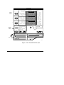
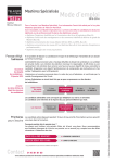
Table of Contents Zone Terminal User’s Manual Introduction 1 ● About This Manual 1 ● Overview of the Zone Terminal 3 ● Features 3 ● Capabilities 4 ● Operating Modes 6 Getting Started 9 ● Displays, Symbols, Keys, and Buttons ● Installing the Plastic Labels 10 ● Connecting the Zone Terminal 11 ● Zone Terminal After Connection 14 ● Alarm Status 15 ● Entering Your Password 16 © February, 1994 Johnson Controls, Inc. Order No. 633.5 9 iii Making ZT Adjustments ● Adjusting Control Settings 21 ● Occupied Extend 23 ZT Time Scheduling 25 ● Overview 25 ● Setting the Current Time 26 ● Setting Today’s Date 30 ● Planning the Time Schedule 32 ● Choosing the Day of the Week 35 ● Time Scheduling for Holidays 37 ● Temporary Time Scheduling 39 ● Setting Begin/End Times 41 Troubleshooting ● iv 21 Internal Diagnostic Errors 45 49 Appendix A: Time Scheduling Worksheets 51 Appendix B: Glossary 55 Index 63 Zone Terminal User’s Manual Introduction About This Manual The manual contains step-by-step instructions for using the Zone Terminal (ZT). It presents information in the order that you need it. The manual does not explain how the Zone Terminal is configured. For this type of information, see the ZT section of the HVAC PRO for Windows User’s Manual. Using the Manual The manual assumes you are familiar with your building’s general HVAC operation. Examples The manual includes examples of the ZT screen that are as realistic as possible, but may not directly apply to your HVAC system. Controls, Inc. 1 User’s Manual Organization Four major sections describe how to use the Zone Terminal. Appendix A includes Time Scheduling Worksheets, and Appendix B is a glossary of terms. Introduction and Overview Explains in general terms the features and operating modes of the Zone Terminal. Getting Started Includes an explanation of the Keys, Displays, and Symbols on the Zone Terminal. Also includes an explanation of the Zone Terminal inserts and how to install them. In addition, this section instructs the user about handling Alarm Status, connecting the Zone Terminal, and entering the Password. Making ZT Adjustments Includes specific instructions for making set point adjustments with the Zone Terminal. Also explains a special feature, Occupied Extend. ZT Time Scheduling Instructs on how to set the current time and date, and setting Begin/End times for Occupied, Warmup, and Shutdown conditions. Also explains regular day of the week, holiday, and temporary scheduling. 2 Zone Terminal User’s Manual Overview of the Zone Terminal The Zone Terminal (ZT) is a hand-held or wall-mounted device that monitors and adjusts your heating and air conditioning system within a specific building zone. The ZT allows easy access to any zone function available to your password level. A telephone-style jack connects the ZT to a Johnson Controls: Features ● Unitary (UNT) Controller or Variable Air Volume (VAV)Controller through a TE-6100 or TE-64/6500 Series Zone Sensor. ● AHU101 Controller either directly, or through a Function Module Kit (FMK100) or Relay Kit (RLY100) The ZT provides: ● portability ● zone system security with three levels of password ● simultaneous monitoring of 3 different settings or values plus 18 status points ● easy operation with only seven buttons ● flashing numbers to show which items are ZT adjustable ● flashing symbols to notify you of alarm conditions Zone Terminal User’s Manual 3 Capabilities With the ZT, you can: ● quickly identify an alarm and its location ● monitor and adjust up to 18 different settings ● extend a daily time schedule with the Occupied Extend feature ● add or modify daily, holiday, and temporary time schedules To familiarize yourself with the ZT, refer to Figure 1 on the next page. 4 Zone Terminal User’s Manual Building 3 Floor 4 AHU12 ZONE TEMP OUTDOOR TEMP ZONE HUMIDITY OUTDOOR HUM TEMP OCC D isp lay B utton 1 2 COOL SET POINT HEAT SET POINT WARMCOOL ADJ ACT CLG SP ACT HTG SP 3 DISCH TEMP CLG % ON HTG % ON ECON % OPEN MIN POS % OPN INSERT 12 ON Display Area 11 OFF FAN COOL STG COOL STG HEAT STG HEAT STG OCCUPIED #1 #2 #1 #2 Display Area 21 A/C LIM OPN CHECK FAN CHECK CLG CHECK HTG CHECK ECON DIRTY FILTR Display Area 31 FAN STATUS ECON ENABLE TEMP OCC WARMUP MODE CLG LOCKOUT HTG LOCKOUT ALARM M ode Selector Panel MONITOR ADJUST TIME SCHEDULE PASSWORD ENTER Doo r MAP1RT Figure 1: Zone Terminal with Door Open Zone Terminal User’s Manual 5 Operating Modes Four Operating Modes--Monitor, Password, Adjust, and Time Schedule--provide security and allow you to monitor, adjust, and set time schedules for an individual zone. Monitor Mode As soon as the ZT is connected, it completes a self-check, and then starts up in the Monitor Mode. The Monitor Mode allows you to view up to three settings, or sensed values, at one time for your HVAC system. To monitor your system, you must use a clear plastic Insert (a custom-made label) to relate the ZT’s output to your particular system. (See the Installing the Plastic Labels--Insert section.) You can simultaneously monitor your HVAC system in three different ways: ● Monitor up to three different settings or sensed values. A maximum of six items are accessible in each of the three displays. ● Read the symbols to the right of the display numbers to learn the on/off status of various inputs, outputs, or modes | = On status; ❍ = Off status). This provides continuous monitoring of 18 different statuses (on/off). ● Monitor alarm status--a flashing red alarm light and any flashing symbol |, ❍, ▲--visually notifies you when your HVAC system has an alarm condition. 6 Zone Terminal User’s Manual Password Mode Adjust Mode The Password Mode allows users with the proper access rights to adjust system set points and time scheduling. There are three levels of password access: ● Monitor and adjust--password allows user access to adjust only system set points ● Monitor, adjust and time scheduling--password allows user access to all ZT features and capabilities, but the system is still password protected ● No password--user is allowed to access all ZT features and capabilities without entering a password In the Adjust Mode, the ZT displays information in each of the three numerical displays. Typically, the displays are set up so that the relationship between the values can be viewed simultaneously. For example: Display 1 = Room Temperature Display 2 = Room Set Point Display 3 = Output Command This operating mode allows you to adjust any flashing set points that are authorized by your Password. Set points adjusted by the ZT remain in effect until you change them. Zone Terminal User’s Manual 7 Time Schedule Mode In the Time Schedule Mode, you can monitor or adjust the days and Begin/End times for Occupied, Warmup, and Shutdown conditions. You can also set up holiday and temporary schedules. Time Schedule Mode is available to those who have appropriate Password Access. 8 Zone Terminal User’s Manual Getting Started Displays, Symbols, The Zone Terminal simultaneously displays three set Keys, and Buttons points or sensed values. In addition, flashing symbols indicate when items are in a state of alarm. The keys, buttons, displays, and symbols are explained below. Table 1: Displays, Symbols, Keys, and Buttons Displays, Symbols, Keys, Buttons Description Display Button Select the value you want to monitor or adjust. 1, 2, 3 Enter Key Use to commit your changes. Adjustments are not processed unless you press Enter. Flashing Numbers Appear in Display 1, 2, or 3 to indicate numbers you can adjust. Numbers that do not flash are monitor only numbers. Flashing ▲, ❍, | Shows an item is in alarm. Mode Selector Button Press this button to select Operating Modes: Monitor, Adjust, Password, Time Scheduling. A green Mode Indicator light moves through the modes. On/Off Status Symbols Observe On/Off conditions of a point in the HVAC controller with | for On or ❍ for Off these symbols. A bar | for On, a circle ❍ for Off. These are always monitor only items. If the symbol flashes, the item is in alarm. Red Alarm Light Flashes anytime a problem exists regardless of which Operating Mode you have entered. Up ↑ or Down ↓ Arrow Keys Use these keys to adjust a flashing number. ● Appears in the value displays, and corresponds to the item you are monitoring or adjusting. Zone Terminal User’s Manual 9 Installing the Plastic Labels To use the ZT, you need one of two different types of plastic labels, which are included with your ZT: Insert The clear plastic Insert is a custom-made label unique to your HVAC system. Use this Insert when monitoring or adjusting specific items of your system: 1. With the ZT on a flat surface, press the white tab with your index finger (Figure 2). 2. Pull the front cover of the ZT away from the back and slide the Insert into position. 3. Press the ZT together and plug in the telephone-style jack from the controller. With the Insert in place and the ZT connected, the ● in the top position of each display lines up with the first word. INSERT3A Figure 2: Installing the Insert 10 Zone Terminal User’s Manual Time Schedule Overlay Use the light gray Time Schedule Overlay when performing any function in the Time Schedule Mode. The Overlay, made to cling to the ZT, sticks around the outside of the display area. Note: Do not open the ZT case to use the Time Schedule Overlay. Connecting the Zone Terminal You can wall-mount the ZT, or use it as a portable tool for convenient access to any zone functions available to your password level. UNT/VAV Connection A telephone-style jack connects the ZT to a Johnson Controls Unitary Controller (UNT) or Variable Air Volume (VAV) Controller through a TE-6100 or TE-64/6500 Series Zone Sensor. See Figure 3. Remove cover. Zone Terminal (back) Connected to a TE-6100 Series Zone Sensor Zone Terminal (back) Connected to a TE-6500 Series Zone Sensor SENSORS Figure 3: Connect ZT through a TE-6100 or TE-64/6500 Series Zone Sensor Zone Terminal User’s Manual 11 AHU Controller Connection A telephone-style jack connects the ZT to a Johnson Controls AHU-101 Controller (Figure 4) either directly or through a Relay Kit (Figure 5) or a Function Module Kit (Figure 6). Connect ZT here. Remove cover Open Door AHUCTRBD Figure 4: Connecting ZT to AHU-101 12 Zone Terminal User’s Manual Connect ZT here. RLYZT Figure 5: ZT to Relay Kit (AS-RLY-100) Note: Zone Bus wiring must be connected to Relay Kit or Function Module Kit. Connect ZT here. FMKNOTE Figure 6: ZT to Function Module Kit (AS-FMK-100) Zone Terminal User’s Manual 13 Figure 7 shows an example of the ZT and its displays after connection. Zone Terminal After Connection D isp lay Item L ist W arning Sig nal Display Ind icator Dot ROOFTOP ZTU Disp lay Button 1 2 COOL SET PT HEAT SET PT WARMCOOL ADJ ACT CLG SP ACT HTG SP 3 DISCH TEMP CLG % ON HTG % ON ECON % OPEN MIN POS % OPN M ode Selector Bu tton M ode Selector Panel INSERT 12 Display Area 21 Display Area 31 Operating Mode Indicator MONITOR ADJUST TIME SCHEDULE PASSWORD ENTER ON Display Area 11 OUTDOOR AIR ZONE TEMP STATIC STEPT MIXED AIR LL SP NIGHT HTG STPT NIGHT CLG STPT O n/Off Status OFF FAN COOL STG #1 COOL STG #2 HEAT STG #1 HEAT STG #2 OCCUPIED A/C LIM OPN CHECK FAN CHECK CLG CHECK HTG CHECK ECON DIRTY FILTR FAN STATUS ECON ENABLE TEMP OCC WARMUP MODE CLG LOCKOUT HTG LOCKOUT ALARM Alarm Light Up/Down Arrow Keys D oor MAP1RT4 Figure 7: Connected ZT, Insert in Place 14 Zone Terminal User’s Manual Alarm Status The ZT indicates an alarm as follows (Figure 7): ● ● ● The warning signal ▲ flashes to the right of the point name if the system operating values are in alarm. The On/Off Status bar | or circle ❍ flashes when an On/Off status is in alarm. The red alarm light to the right of the Mode Selector Panel flashes when any of the above items are in alarm. Alarms cannot be cleared with the ZT. The problem must be corrected by maintenance or repair of the affected item. Zone Terminal User’s Manual 15 Entering Your Password If your system uses the Password feature, you must enter the Password before you can make changes to the set points, or before you gain access to Time Scheduling. To enter your Password: 1. Open the Mode Selector Panel by pulling the door down. 2. Press the Mode Selector Button until the green Mode Indicator Light moves next to the word Password. When the Mode Selector Button is in the Password position, a number appears in Display 1. This number must match the number on the top, center of your Insert. If the numbers do not match, the data that appears in the displays will not match the description on the Insert. Replace the incorrect Insert. DISPLAY AREA 1 ROOFTOP ZTU INSERT 12 ON OFF ZONE TEMP OUTDOOR TEMP ZONE HUMIDITY OUTDOOR HUM TEMP OCC FAN COOL STG #1 COOL STG #2 HEAT STG #1 HEAT STG #2 OCCUPIED COOL SET PT HEAT SET PT WARMCOOL ADJ ACT CLG SP ACT HTG SP A/C LIM OPN CHECK FAN CHECK CLG CHECK HTG CHECK ECON DIRTY FILTR DISCH TEMP CLG % ON HTG % ON ECON % OPEN MIN POS % OPN FAN STATUS ECON ENABLE TEMP OCC WARMUP MODE CLG LOCKOUT HTG LOCKOUT HOLIDAY NUMBER ALARM MONITOR ADJUST EENT NTE ERR TIME SCHEDULE MONITO R TIME SCHEDULE ADJUST PASSWO RD -PASSWORDENTER CONFIG1 Figure 8: Matching the Insert Number 16 Zone Terminal User’s Manual INSERT 12 N ote: Nu m be r in Display 1 m ust m atch typed nu m be r on the In sert. Three numbers appear in Display 3. The number in the left position flashes. DISPLAY AREA 3 RO OFTOP ZTU IN SERT 12 ON OFF COOL SET PT HEAT SET PT WARMCOOL ADJ ACT CLG SP ACT HTG SP FAN COOL STG #1 COOL STG #2 HEAT STG #1 HEAT STG #2 OCCUPIED A/C LIM OPN CHECK FAN CHECK CLG CHECK HTG CHECK ECON DIRTY FILTR DISCH TEMP CLG % ON HTG % ON ECON % OPEN MIN POS % OPN FAN STATUS ECON ENABLE TEMP OCC WARMUP MODE CLG LOCKOUT HTG LOCKOUT HOLIDAY NUMBER ZONE TEMP OUTDOOR TEMP ZONE HUMIDITY OUTDOOR HUM TEMP OCC MONITO R ADJUST TIME S CHEDULE ALA RM MONIT OR PASS WORD ADJUS T E NT ER TIME SCHEDULE -PASSWORDENTER PSWD3 Figure 9: Entering Password 3. Press the Up ↑ or Down ↓ Arrow key until the first number of your Password appears in the flashing position. Press Enter. The middle number in Display 3 begins flashing. 4. Press the Up ↑ or Down ↓ Arrow key until the middle number of your Password appears in the flashing position. Press Enter. The third, or far right number, begins flashing. Zone Terminal User’s Manual 17 5. Press the Up ↑ or Down ↓ Arrow key until the last number of your Password appears in the flashing position. Press Enter. You must press Enter for each of the three numbers in your Password in order for the ZT to recognize it as a valid Password. If you do not press Enter each time, the ZT ignores your Password entry and you cannot gain access to Adjust Mode or Time Scheduling Mode. After you press Enter for the last number of your Password, the green Mode Indicator Light moves next to the word Adjust in the Mode Selector Panel. If it does not go to this position, the Password is incorrect. You can now begin changing values or set points in the Adjust Mode, or press the Mode Selector Button to move the green Mode Indicator Light to the Time Schedule position. Time Scheduling may require a different Password. Note: The ZT is preset to time out after a 1 to 15-minute interval between entries. If you wait too long to enter an adjustment, you must re-enter your Password. This prevents unauthorized use of the ZT if you forget to cancel your Password. 18 Zone Terminal User’s Manual Cancel Password After entering the Password, you can easily cancel without waiting for the Zone Terminal to time out. 1. Press the Mode Selector Button until the green Mode Indicator Light moves next to the word Password. 2. Press Enter three times. In doing this, you have entered zeroes as the Password. Access is immediately canceled because 000 is not a valid Password. Zone Terminal User’s Manual 19 20 Zone Terminal User’s Manual Making ZT Adjustments Adjusting Control This section of the manual is for users who have Password access to the Adjust Mode. Settings If you haven’t already entered your Password, you must do so. See Entering Your Password. You can adjust only a flashing number with the ZT. If the number does not flash, that item is a monitor only item. Adjust Control Settings in Display 1, 2, or 3 as follows: 1. Press the Mode Selector Button until the green Mode Indicator Light moves next to the word Adjust. 2. Press either Display Button 1, 2, or 3 to locate adjustable items, which are indicated by flashing numbers. If you continue pressing the display buttons, the dot ● in each display changes positions and the corresponding number appears. 3. Press the Up ↑ or Down ↓ Arrow key until you reach the number you want to enter. If you hold down the Up ↑ or Down ↓ Arrow keys, you can speed through the numbers more quickly. Press Enter. Zone Terminal User’s Manual 21 After you press Enter, the numbers stop flashing for a few seconds. This pause tells you the ZT has processed your adjustment. 4. Press any of the Display Buttons to make other adjustments, and repeat Steps 2 and 3. Notes: Some adjustable set points have high and low limits beyond which you cannot adjust them. For example, a heating set point may have an upper limit of 86°F (30°C). When you make adjustments, they become permanent in the ZT. To make a temporary change, write down the original value before making the change so you can re-enter it later. 22 Zone Terminal User’s Manual Occupied Extend Occupied Extend is a special feature that lets you temporarily turn the system on for an extended period of time without going into the Time Schedule Mode. If your system uses the Occupied Extend feature, you’ll find it listed on the Insert. No matter what Begin/End time you have scheduled for the current day, you simply decide how long the system should remain on. For example: It is currently 3:30 P.M. and you want the building to stay on until 11 P.M. This is an extension of 7 hours and 30 minutes, which you enter on the ZT. You can enter any amount of time from 00:00 to 23:59 in Occupied Extend. After the Occupied Extend Schedule runs, the ZT returns to its regular settings and the erases the Occupied Extend Schedule. To set Occupied Extend: Remember, if you haven’t already entered your Password, you must do so. Press the Mode Selector Button until the green Mode Indicator Light moves next to the word Adjust. 1. Press the appropriate Display Button until the ● is next to the words Occupied Extend . The hours flash. 2. Press the Up ↑ or Down ↓ Arrow key until you reach the hours you want (0-23). In the above example, we would choose 7. Press Enter. The minutes flash. Zone Terminal User’s Manual 23 3. Press the Up ↑ or Down ↓ Arrow key until you reach the minutes you want (0-59). Based on our example, we would choose 30. Press Enter. The hours begin flashing again. These numbers do not pause after you enter them. You must press Enter after making an adjustment. If you do not press Enter, the ZT returns the number to its previous setting. Note: The ZT is preset to time out after a certain amount of time passes between entries. If you wait too long to enter an adjustment, you must re-enter your Password. This prevents unauthorized use of the ZT if you forget to cancel your Password. 24 Zone Terminal User’s Manual ZT Time Scheduling Overview This section of the manual is for users who have Password access to Time Scheduling. To schedule time, you: 1. Set current time. 2. Set today’s date. 3 Plan the schedule. 4. Choose the day of the week. 5. Set holiday and temporary schedules. 6. Set Begin/End times for Occupied, Warmup, and Shutdown. Zone Terminal User’s Manual 25 Setting the Current Time 1. Place the plastic Time Schedule Overlay on the ZT. The Overlay clings to the face of the ZT. See Insert in the Installing the Plastic Label section. 2. Enter your Password if you have not already done so. See Entering Your Password. 3. Press the Mode Selector Button until the green Mode Indicator Light moves next to the words Time Schedule. See Figure 11 showing the Time Schedule Overlay in place. 26 Zone Terminal User’s Manual The ● in Display 1 is next to the words Current Time. The number in the Hours position flashes. 4. If the number in the Hours position is correct, press Enter. If the number needs changing, press the Up ↑ or Down ↓ Arrow keys to reach the desired number of the current hour (1-23). Press Enter. The numbers in the Minutes position begin flashing. Set the hours. TIME SCHEDULE ON OFF DISPLAY AREA 1 TIM E S CHED ULE CURRENT TIME TODAY'S DATE DAY OF WEEK HOLIDAY NUMBER TE MP OR ARY SCHD HOLIDAY DATE BEGI N O CCUPI ED END O CCU PIED BEGIN WA RMUP E ND WARMU P BEGI N S HUTDO WN END S HUT DOWN ON OF F SUNDAY MONDAY TUESDAY WEDNESDAY THURSDAY FRIDAY 1 2 3 4 5 6 SATURDAY 7 OCCUP CMD WARMUP CMD CURRENT TIME TODAY'S DATE DAY OF WEEK HOLIDAY NUMBER TEMPORARY SCHD SUNDAY MONDAY TUESDAY WEDNESDAY THURSDAY FRIDAY 1 2 3 4 5 6 SATURDAY 7 Use Up /Dow n Arrow keys to reach desired n um ber. T hen press En te r. SHUTDOWN CMD ALARM M ONI TOR A DJU ST T IME SCHE DUL E P ASS WORD ENTER S et the minute s. TIME SCHEDULE ON OFF DISPLAY AREA 1 CURTMS1 CURRENT TIME TODAY'S DATE DAY OF WEEK HOLIDAY NUMBER TEMPORARY SCHD SUNDAY MONDAY TUESDAY WEDNESDAY THURSDAY FRIDAY 1 2 3 4 5 6 SATURDAY 7 Use Up /Dow n Arrow keys to reach desired num ber. T hen press En te r. Figure 10: Setting the Current Time Zone Terminal User’s Manual 27 5. If the number in the Minutes position is correct, press Enter. If the Minutes need changing, press the Up ↑ or Down ↓ Arrow keys to reach the desired number (0059). Press Enter. The Hours number flashes again. You can reset the current time, or go on to your next adjustment. 28 Zone Terminal User’s Manual Day Numbers Display Item List Display Indicator Dot On/Off Status ON TIME SCHEDULE CURRENT TIME TODAY'S DATE DAY OF WEEK HOLIDAY NUMBER TEMPORARY SCHD Display Button 1 HOLIDAY DATE OFF Display A rea 1 1 SUNDAY MONDAY TUESDAY WEDNESDAY THURSDAY FRIDAY 1 2 3 4 5 6 Display A rea 2 1 SATURDAY 7 2 BEGIN OCCUP END OCCUP BEGIN WARMUP END WARMUP BEGIN SHUTDOWN END SHUTDOWN 3 OCCUP CMD WARMUP CMD SHUTDOWN CMD Operat ing M ode Indicator Mode Selector Button Mode Selector Panel Display A rea 3 1 ALARM MONITOR ADJUST TIME SCHEDULE PASSWORD ENTER Up/Down Arrow K eys Door MAP2TS Figure 11: Zone Terminal with Time Scheduling Overlay Zone Terminal User’s Manual 29 Always enter time in 24-hour format. For example: 5:00 P.M. is 17:00. No alarms apply to Time Scheduling. If you see the red alarm light flashing when in the Time Scheduling Mode, an alarm condition exists in the HVAC system. See Alarm Status section. Note: Setting Today’s Date ZT Time Scheduling functions only with controllers for which the ZT was configured. In most cases, the ZT Time Scheduling is accessible when it is permanently mounted and dedicated to a specific controller. Only individuals with Time Scheduling Password Access can set Today’s Date. This section of the manual is for users who have Password access to Time Scheduling. Remember, the Time Schedule Overlay must be on the face of the ZT. Enter your Password if it is required, and you haven’t already done so. 1. Press the Mode Selector Button until the green Mode Indicator Light moves next to the words Time Schedule. 2. Press Display Button 1 until the ● is next to the words Today’s Date. The month flashes. 30 Zone Terminal User’s Manual TIME SCHEDULE DISPLAY AREA 1 ON CURRENT TIME TODAY'S DATE DAY OF WEEK HOLIDAY NUMBER TEMPORARY SCHD OFF SUNDAY MONDAY TUESDAY WEDNESDAY THURSDAY FRIDAY 1 2 3 4 5 6 Use U p/Down Arrow keys to reach desired m on th num ber. Then press Enter. TIME SCHEDULE TIME TODAY'S DATE DAY OF WEEK HOLIDAY NUMBER TEMP SCHEDULE HOLIDAY DATE OCCUP START OCCUP STOP WARMUP START WARMUP STOP SHUTDOWN START SHUTDOWN STOP MONITO R ADJUST TIME S CHEDULE PASSWO RD ON OFF SUNDAY MONDAY TUESDAY WEDNESDAY THURSDAY FRIDAY SATURDAY OCCUP CMD WARMUP CMD 1 2 3 4 5 6 7 TIME SCHEDULE DISPLAY AREA 1 ON CURRENT TIME TODAY'S DATE DAY OF WEEK HOLIDAY NUMBER TEMPORARY SCHD OFF SUNDAY MONDAY TUESDAY WEDNESDAY THURSDAY FRIDAY 1 2 3 4 5 6 SHUTDOWN CMD ALARM Use U p/Down Arrow keys to reach desired day num ber. Then press Enter. ENT ER TIME SCHEDULE DISPLAY AREA 1 ON CURRENT TIME TODAY'S DATE DAY OF WEEK HOLIDAY NUMBER TEMPORARY SCHD MODA1 OFF SUNDAY MONDAY TUESDAY WEDNESDAY THURSDAY FRIDAY 1 2 3 4 5 6 Use U p/Down Arrow keys to reach desired yea r num b er. Then press Enter. Figure 12: Setting Today’s Date 3. If the month is correct, press Enter. If the month needs changing, press the Up ↑ or Down ↓ arrow keys until you reach the correct month (112). Press Enter. The day of the month flashes. Zone Terminal User’s Manual 31 4. If the day is correct, press Enter. To change the day, press the Up ↑ or Down ↓ arrow keys until you reach the correct day of the month (131). Press Enter. After entering the correct month and day, the current year setting flashes in Display 1. 5. If the year is correct, press Enter. To change the year, press the Up ↑ or Down ↓ arrow keys to set the correct year. Press Enter. The month and day of the year reappear in Display 1 with the month flashing. You are now ready to plan and enter the Time Schedule. Note: Planning the Time Schedule The ZT changes the necessary date automatically for Leap Year. However, you must manually adjust the ZT for Daylight Saving Time changes. Time Scheduling with the ZT is convenient and easy, but you’ll want to start with a plan. In Appendix A, you’ll find ZT Scheduling Worksheets to help plan your Occupied, Warmup, and Shutdown schedules. 32 Zone Terminal User’s Manual Time Schedule Priority Rules of Time Scheduling The Zone Terminal sets the Time Schedule based on the following order of priority: 1. N2 Bus 2. Occupied Extend 3. Temporary Schedule 4. Holiday Schedule 5. Weekly Schedule ● The Zone Terminal reads and compares only one Begin and one End time for the current day. ● Once Midnight is reached, the next day’s schedule takes over. ● You must schedule ONE BEGIN and ONE END time for EACH day. This applies to Occupied, Warmup, and Shutdown. To avoid an unwanted time scheduling change: If your scheduled earlier time is the... And you want to the system to stay Set Begin (On) time ON until Midnight End (Off) time at 24:00 End (Off) time OFF until Midnight Begin (On) time at 24:00 You want system on until Midnight Set End (Off) time at 24:00 For example: Begin (On) is set for 6:00 . . . Zone Terminal User’s Manual 33 Midnight is defined as 00:00. The useful scheduling range is 00:00 through 23:59. The time setting 24:00 flags the ZT to continue a schedule over two or more days. Note: In some cases, you may want to cancel Zone Terminal scheduling commands. You can do this by scheduling identical Begin/End times with the Zone Terminal. See Setting Begin/End Times. To continue with Time Scheduling, read Choosing the Day of the Week. Then refer to Setting Begin/End Times. 34 Zone Terminal User’s Manual Choosing the Day Before entering your Time Schedule, you must first choose the day of the week you wish to adjust. A number of the Week from 1 through 7 represents each day of the week as shown on the right of the time schedule overlay. TIME SCHEDULE CURRENT TIME TODAY'S DATE DAY OF WEEK HOLIDAY NUMBER TEMPORARY SCHD HOLIDAY DATE ON Day of Week OF F SUNDAY MONDAY TUESDAY WEDNESDAY THURSDAY FRIDAY 1 2 3 4 5 6 SATURDAY 7 BEGI N OC CUPI ED END OCC UPIE D BEGIN WARMUP END WARMUP OCCUP CMD BEGIN SHUTDOWN END SHUTDOWN SHUTDOWN CMD MONITOR WARMUP CMD TIME SCHEDULE DISPL AY AREA 1 CURRENT TIME TODAY'S DATE DAY OF WEEK HOLIDAY NUMBER TEMPORARY SCHD ON OFF SUNDAY MONDAY TUESDAY WEDNESDAY THURSDAY FRIDAY 1 2 3 4 5 6 Use Up/Down Arrow keys to reach desired number. Then press Enter. ALARM ADJUST TIME SCHEDULE ACCSEE NUMBER ENTER DAOFWK Figure 13: Choosing the Day of the Week Remember, the Time Schedule Overlay must be on the face of the ZT. Enter your Password if it is required, and you haven’t already done so. The far right side of the ZT lists each day of the week. You’ll find a bar | next to the current day of the week. That is, if today is Sunday, the bar | will be next to the number 1 (Figure 13). 1. Press the Mode Selector Button if necessary, until the green Mode Indicator Light moves next to the words Time Schedule. Zone Terminal User’s Manual 35 2. Press Display Button 1 until the ● is next to the words Day of the Week. The number in Display 1 flashes. 3. Press the Up ↑ or Down ↓ arrow keys until you reach the appropriate number of the day of the week (1-7). After you press the Up ↑ or Down ↓ arrow key, Displays 2 and 3 are blank. Press Enter. The flashing pauses for a few seconds. This tells you the ZT recognizes that you have entered a day you wish to adjust or monitor. 4. Press Display Button 3 to enter your planned Time Schedule. Refer to the Setting the Begin/End Times section for more information on Time Scheduling. 5. If you wish to set another day, repeat Steps 2 through 4. Note: You must press Enter after each number. If you do not press Enter, the ZT will return to the previous setting. Remember, you have made changes only to the day of the week you entered in Display 1. Now Refer to the Setting the Begin/End Times section for more information on Time Scheduling. 36 Zone Terminal User’s Manual Time Scheduling for Holidays You can schedule up to 10 holidays in advance. Holidays are numbered from 1-10, and each holiday number can be assigned to a specific date during the year. The time Schedule Overlay must be on the face of the ZT. Enter your Password if it is required. Choosing the Holiday Press Display Button 1 until the ● is next to the words Holiday Number. See Figure 14. 1. TIME SCHEDULE ON OFF Disp lay Area 11 TIME SCHEDULE CURRENT TIME TODAY'S DATE DAY OF WEEK HOLIDAY NUMBER TEM PORARY SC HD HOLIDAY DATE ON OFF SUNDAY MONDAY TUESDAY WEDNESDAY THURSDAY FRIDAY 1 2 3 4 5 6 SATURDAY SUNDAY MONDAY TUESDAY WEDNESDAY THURSDAY FRIDAY CURRENT TIME TODAY'S DATE DAY OF WEEK HOLIDAY NUMBER TEMPORARY SCHD 7 Disp lay Area 21 BEGIN OCCUPIED END OCCUPIED BEGIN WARMUP END WARMUP BEGIN SHUTDOWN END SHUTDOWN 1 2 3 4 5 6 OCCUP CMD WARMUP CMD ON OFF SATURDAY HOLIDAY DATE 7 SHUTDOWN CMD ALARM MONI TOR ADJU ST TIME SCHEDUL E PASS WORD E NT ER Disp lay Area 31 HOLIDAY BEGIN OCCUPIED END OCCUPIED BEGIN WARMUP END WARMUP BEGIN SHUTDOWN END SHUTDOWN ON OFF OCCUP CMD WARMUP CMD SHUTDOWN CMD Figure 14: Choosing the Holiday 2. To choose a different holiday to monitor or adjust, press the Up ↑ or Down ↓ Arrow key until Display 1 shows the holiday you want (1-10). After pressing the Up ↑ or Down ↓ arrow key, Displays 2 and 3 are blank. Press Enter. Zone Terminal User’s Manual 37 The flashing holiday number pauses, which indicates the ZT recognizes you want to monitor or adjust that particular holiday number. After choosing the Holiday Number in Display 1, you can either set the month and day in Display 2, or adjust the Begin/End times in Display 3. Changing the Holiday Date Some holidays like the Fourth of July and New Year’s Day always have the same date. Others, like Labor Day or Memorial Day, need to be reassigned to the correct date each year. You must adjust each holiday one at a time. After you have entered your Password, and after you choose the number of the Holiday in Display 1: 1. Press Display Button 2. The month flashes. 2. Press the Up ↑ or Down ↓ Arrow key until you reach the month you wish to enter (1-12). Press Enter. The day of the month begins flashing. 3. Press the Up ↑ or Down ↓ Arrow key until you reach the day of the month you wish to enter (1-31). Press Enter. The month begins flashing again. There is no pause after entering these numbers. 4. Press Display Button 3 to enter your planned Holiday Time Schedule. 38 Zone Terminal User’s Manual 5. If you wish to set another holiday, repeat Steps 1 through 4. Refer to Setting the Begin/End Times for each Command. Notes: As you adjust the date and the Begin/End times, you are adjusting only the holiday whose number appears in Display 1. The date entered is based on the current year. You can cancel a holiday schedule by setting the Begin and End Time to 0:00. You must press Enter each time you enter a number. If you do not press Enter, the ZT will return to its previous setting. Temporary Time Scheduling The ZT allows you to set one temporary time schedule that can be activated for any day of the year. This schedule runs only on the date you specify. After the schedule runs, the ZT returns to its regular settings and the temporary schedule is erased. 1. Press Display Button 1 until the ● appears next to the words Temporary Schd. 2. Choose the date you want to set by pressing Display Button 2. The number in the month position flashes. 3. Press the Up ↑ or Down ↓ Arrow key until you reach the month you wish to enter (1-12). Press Enter. The day flashes. Zone Terminal User’s Manual 39 4. Press the Up ↑ or Down ↓ Arrow key until you reach the number for the day of the month you wish to enter (1-31). Press Enter. The month begins flashing. There is no pause after these numbers are entered. 5. Press Display Button 3 to enter the times for your planned Temporary Schedule. Refer to the section Setting the Begin/End Times. Note: You can schedule only one Temporary Schedule. As soon as this Temporary Schedule has run its course, the ZT resumes regular scheduling. You may, of course, reset the Temporary Schedule feature over and over again during the year (special holidays, bad weather, shutdowns, etc.) 40 Zone Terminal User’s Manual Setting Begin/End Times You set the Begin/End times for Occupied, Warmup, and Shutdown Commands the same way for: Day of the Week, Holiday, and Temporary Scheduling. Before you start entering Begin and End Times for Time Scheduling, refer to sections in this manual on: ● Planning the Time Schedule ● Choosing the Day of the Week ● Time Scheduling for Holidays ● Temporary Time Scheduling ● Appendix A: Time Scheduling Worksheets Remember, the Time Schedule Overlay must be in place, and you must enter your Password if you haven’t already done so. Schedule only one day at a time. You must set one Begin and one End time for each day. If you are not scheduling a day, enter 00:00 for both the Begin and End Times. Time is always stated in 24-hour format. For example, 5:00 P.M. is stated as 17:00. The useful scheduling range is 00:00 through 23:59. Midnight is defined as 00:00. The time setting of 24:00 flags the ZT to continue a schedule over two days. Refer to the Rules of Time Scheduling section of this document for more information regarding Time Scheduling rules. 1. Press Display Button 3 and select either Begin or End for Occupied, Warmup, or Shutdown. Zone Terminal User’s Manual 41 Disp lay Area 31 TIME SCHEDULE ON CURRENT TIME TODAY'S DATE DAY OF WEEK HOLIDAY NUMBER TEMPORARY SCHD HOLIDAY DATE OFF SUNDAY MONDAY TUESDAY WEDNESDAY THURSDAY FRIDAY 1 2 3 4 5 6 SATURDAY 7 OFF OCCUP CMD Disp lay Area 31 BEGIN OCCUPIED END OCCUPIED BEGIN WARMUP END WARMUP BEGIN SHUTDOWN END SHUTDOWN ON BEGIN OCCUPIED END OCCUPIED ON OFF OCCUP CMD WARMUP CMD SHUTDOWN CMD BEGIN WARMUP END WARMUP WARMUP CMD ALARM MONITOR ADJUST TIME SCHEDULE PASSWORD Disp lay Area 31 ON OFF ENTER BEGIN SHUTDOWN END SHUTDOWN SHUTDOWN CMD SSTIME Figure 15: Occupied, Warmup, and Shutdown Commands--Located in Display 3 When you first press Display Button 3, the ● appears next to the words BEGIN OCCUP (or start). The hours in Display 3 flash. 2. If the hour is correct, press Enter. If the hour needs changing, press the Up ↑ or Down ↓ Arrow key until you reach the new hour setting (0 to-24). Press Enter. The minutes now flash. 42 Zone Terminal User’s Manual 3. If the minutes are correct, press Enter. If the minutes need changing, press the Up ↑ or Down ↓ Arrow key until you reach the new minute setting (00 to 59). Press Enter. The hours flash again. No pause occurs after entering the time. 4. Press Display Button 3 to move to the next Begin or End time you want to change. Repeat Steps 1 through 4 for each day of the week, holiday, or temporary schedule that you want to enter. Note: You must reset the Time of Day entries for Daylight Saving Time. Zone Terminal User’s Manual 43 44 Zone Terminal User’s Manual Troubleshooting Table 2: Troubleshooting Problem Solution Displays remain blank after ZT is connected No power is getting to the ZT – check for appropriate connections Displays show only dashes --------Note: ----- The ZT unit is operational, but not communicating with the controller. Check the Zone Bus wire/controller. The CBLCON switch must be in the NORMAL position. If you do not find wiring errors, download the controller using HVAC PRO, Release 3.0 or later. Displays show only dots ... ... ... The download in the ZT does not match the connected controller, or the download is invalid. Select the correct download (ZT load file) and re-load the ZT. Displays show 99999 An entered number is too large to display. Displays show -9999 An entered number is too small to display. Internal RAM/Processor Error* at power up. External RAM Error* at power up. Displays show Err 01 Displays show Err 02 Displays show Err 03 Displays show Err 04 Displays show Err 05 Displays show Err 06 E2 PROM Error* at power up. ROM (Code) Error* at power up. Battery Bad** at power up. Battery-backed RAM Error* at power up. Continued on next page . . . Zone Terminal User’s Manual 45 Problem (Cont.) Solution Red Alarm light continues to flash. Fix the HVAC problem causing the alarm. No alarm acknowledge or cancel is available. Numbers in the display The insert is not the correct one for this ZT and controller. Verify the insert do not relate to the number by entering Password Mode. items listed on the insert Cannot enter Adjust Mode Have you entered the proper Password? Do you have Password access to this mode? If an N2 Network is present, verify the An otherwise adjustable analog point point is overridden. Release the override. cannot be adjusted If Zone Bus Laptop is connected to the controller, verify the point is overridden. Release the override. Verify the display file for the corresponding configuration in the controller, and make the desired point adjustable. Binary display points are not adjustable No solution. This is normal operation. ZT jumps back to Monitor Mode and Password must be reentered. The ZT keyboard has not received a keystroke for a time equal to the Keyboard Idle Time-out as defined in the ZT PRO (1 to 15 minutes.) Re-enter your password and continue. Either, increase the Idle Time-out in the ZT PRO and re-download. Or, disable the feature in the ZT PRO by entering zero (0) and re-download. Cannot enter time Scheduling Mode. Have you entered the proper Password? Do you have Password access to this mode? Is the ZT plugged into the controller selected for Time Scheduling? Continued on next page . . . 46 Zone Terminal User’s Manual Problem (Cont.) Solution Time and Date cannot be adjusted and N2 is no longer online. Wait ten minutes for controller to release control of the N2 status after the N2 bus was disconnected. If no N2 is connected, or if there is N2 but it has been offline for a least ten minutes, and time and date cannot be adjusted, call the Johnson Controls, Inc. office. The ZT is not running the user's intended schedule. Ensure a higher priority schedule is not running in place of the desired schedule. Schedule priorities are: • N2 Schedule • Occupied Extend • Temporary Schedule • Holiday schedule • Daily Schedule Verify the ZT schedules to ensure they are what you intend. Refer to the Time Scheduling section of this document for information on using schedules across day boundaries and the use of 24:00 flag. One minute lapse in time scheduling has occurred at Midnight Enter 24:00 to cross the day boundary. ZT stays Occupied after Ensure the ZT schedule is as desired. If the schedule for Occupied is disabled Occupied Extend (Begin and End times equal) when the expires Occupied Extend time expires, the ZT reverts to the last schedule. Since the schedule is inactive, Occupied remains in its last state which was ON. Continued on next page . . . Zone Terminal User’s Manual 47 Problem (Cont.) Solution Time Schedule binaries (Occupied, Warm-up, Shutdown) are changing while the user edits the ZT Time Schedule. You are editing the schedule during the active day of the week or holiday, and the present time is in the window of adjustment. Make day of week schedule changes at times other than during the desired Begin/End times. For holidays, change the date so that it is not the current date. Edit the schedule, then set the desired date for the schedule. Alarms show up when the system goes into unoccupied mode or shutdown. Disable alarm reporting by using HVAC PRO for the controller configuration or the ZT PRO for binary data points (BDs). Use a ZTU100-1. * For Errors 1, 2, 3, 4, and 6--Repower the device two or three more times. If the error still exists, disconnect the ZT and run diagnostics by holding the Display Key 1 and Adjust Down(↓) Key when the phone jack is first plugged in. The word DIAG appears on Display 1 at the start, and all display segments light up for Pass. When all segments light, push Display Key 1 two times, and then follow the prompts. ** For Error 5--This is only a warning indicating the battery-backed data, specifically Time Scheduling, is lost. If you press Enter, the ZT loads the default time schedule, and you may continue. Replace the battery at your earliest convenience. Use a Panasonic® lithium or Ray-O-Vac®–battery number BR2325. 48 Zone Terminal User’s Manual To run the ZT's internal diagnostics, hold the Display Key Internal Diagnostic Errors 1 and Adjust Down (↓) Key when you plug in the phone jack. The word DIAG appears on Display 1 at the start, and all display segments light up for Pass. When all segments light, push Display Key 1 two times, and then follow the prompts. Figure 16 illustrates what the ZT is reporting in the event of an internal diagnostic failure. The digit “1” appears in display 2 or 3 to indicate where the error has occurred. D is p la y A r e a 1 1 D is p la y A re a 2 1 Internal RAM External RAM D is p la y A re a 3 1 ROM Test 2 E PROM BatteryBacked RAM Test DIAGFAIL Figure 16: Internal Diagnostics Zone Terminal User’s Manual 49 50 Zone Terminal User’s Manual Appendix A: Time Scheduling Worksheets To help you plan your time scheduling activities, we’ve included worksheets on the next two pages. Photocopy the: ● ZT Weekly Time Scheduling Worksheet to plan your regular daily schedules ● ZT Holiday Time Scheduling Worksheet, which includes a space for planning a Temporary Schedule Zone Terminal User’s Manual 51 ZT WEEKLY TIME SCHEDULING DAY OF WEEK OCCUPIED BEGIN END WARMUP BEGIN END SHUTDOWN BEGIN END 1 SUNDAY 2 MONDAY 3 TUESDAY 4 WEDNESDAY 5 THURSDAY 6 FRIDAY 7 SATURDAY ZTWEEK 52 Zone Terminal User’s Manual ZT HOLIDAY TIME SCHEDULING HOLIDAY HOLIDAY# DATE OCCUPIED BEGIN END WARMUP BEGIN END SHUTDOWN BEGIN END 1 2 3 4 5 6 7 8 9 10 TEMPORARY SCHEDULE DATE 1 ZTHOL Zone Terminal User’s Manual 53 54 Zone Terminal User’s Manual Appendix B: Glossary AHU 100 Controller Air handling control unit into which a Zone Terminal is connected. Adjust Mode One of four operating modes. Adjust Mode allows you to adjust or change settings in your HVAC system. Alarm Status A symbol (triangle ▲, bar | , or circle ❍) that flashes when a problem exists on a specific monitored or controlled item. In addition, a flashing red alarm light appears to the right of the Mode Selector Panel. Begin/End Times In Time Scheduling, a Begin and End Time must be set for all three types of system conditions; that is: Occupied Command, Warmup Command, and Shutdown Command. Time is always stated in 24-hour format. For example, 5:00 P.M. is stated as 17:00. The useful scheduling range is 00:00 through 23:59. Midnight is defined as 00:00. The time setting 24:00 flags the ZT to continue a schedule over two days. CBLCON (AS-CBLCON-n) A phone cable connector board used to interface a controller to the ZT. Zone Terminal User’s Manual 55 CMD Command. Commands In Time Schedule Mode, refers to the zone conditions of: Occupied (Occup Cmd), Warmup (Warmup Cmd), and Shutdown (Shutdown Cmd). Control Settings Listed on the Insert--items or points which can be monitored or adjusted with the ZT. A total of six items can be listed in each display. Display Numbers that appear in three areas on the face of the ZT, and referred to as Display 1, Display 2, and Display 3. Display Button Buttons located on the left side of the ZT and referred to as Display Button 1, Display Button 2, and Display Button 3. Each button corresponds to the display immediately to the right of the button. Pressing the button allows you to choose another item listed within the same display. Enter A button marked Enter located on the front lower left of the Mode Selector Panel. Function Module Kit (AS-FMK-100) The Zone Terminal connects to a Function Module Kit if the Zone Bus wiring is connected between the FMK and its associated controller. HVAC Heating, Ventilating, and Air Conditioning. 56 Zone Terminal User’s Manual Holiday Number An item on Time Scheduling Display 1--used to identify the holiday. Insert A clear plastic label custom-made for your HVAC system and provided with the ZT. Used only in Monitor and Adjust Operating Modes. Insert xx A number used to identify the correct Insert. Insert xx represents a number specific to your ZT. The number in Display 1 (visible only in Password Mode or for the first few seconds when the ZT is connected) must match the pre-printed Insert xx number on the top, center of the Insert. Mode Selector Button Located in the Mode Selector Panel. A button used to choose which type of operation you will perform: Monitor, Adjust, Time Schedule, or Password. Mode Selector Panel Area inside the drop-down door that includes: Monitor Mode ● Mode Selector Button with green Mode Indicator Lights ● Enter key ● Up ↑ or Down ↓ Arrow keys One of four operating modes that allow you to view settings or sensed values in the displays without making adjustments. Zone Terminal User’s Manual 57 Occupied Normal operating mode for occupant comfort. Occupied Extend A special feature, available in the Adjust Mode, that lets you turn the system on for an extended period of time without going into the Time Scheduling Mode or disturbing an existing time schedule. On/Off Status Insert items listed on the right side of Displays 1, 2, or 3 indicated with a bar | for On (active) and a circle ❍ for Off (inactive). These On/Off Status items are Monitor Only items. Operating Mode Monitor, Adjust, Time Schedule and Password Modes located in the Mode Selector Panel. Password A 3-digit security number that must be entered into the ZT before changes can be made to your HVAC system or to the Time Schedule. 58 Zone Terminal User’s Manual Password Level The Zone Terminal uses three levels of Password security. ● Monitor and adjust--password allows user access to adjust only system set points ● Monitor, adjust and time scheduling--password allows user access to all ZT features and capabilities, but the system is still password protected ● No password--user is allowed to access all ZT features and capabilities without entering a password Password Mode One of four Operating Modes located in the Mode Selector Panel. Password Mode is used to enter Password and verify correct Insert number. (See Insert xx.) Relay Kit (AS-RLY-100) The Zone Terminal connects to a Relay Kit if the Zone Bus wiring is connected between the Relay Kit and its associated controller. Sensed Value Values measured by the controller. For example, temperature, humidity, pressure. Set Point Desired point at which the controller is set. For example, a Zone Temperature Set Point could equal 72°F (22°C). Zone Terminal User’s Manual 59 Shutdown All outputs are commanded off or closed. No control of HVAC equipment occurs. ! Symbols WARNING: If Shutdown is used in temperatureextreme environments, the controller does not protect for low temperature equipment damage. Use other external protection devices. A solid dot ● indicates the item chosen within the three display areas. A bar | next to the day of the week indicates which day is displayed on the ZT. A solid flashing triangle ▲ indicates the corresponding item is in alarm. A bar | for On or a circle ❍ for Off. When flashing, indicates the corresponding On/Off status is in alarm. The flashing red light in the lower right-hand side of the ZT indicates any item above is in alarm. A green Mode Indicator Light corresponds to the Operating Mode displayed in the Mode Selector Panel. 60 Zone Terminal User’s Manual 24-Hour Format Time is always stated in 24-hour format. A complete day is 0:00 to 23:59. 00:00 = Midnight 01:00 = 1:00 A.M. 08:00 = 8:00 A.M. 12:00 = Noon 18:00 = 6:00 P.M. 22:00 = 10:00 P.M. 24:00 = Flag for the ZT to continue a schedule over two days Temporary Schedule A one-time temporary time schedule that operates instead of the weekly schedule for that day. Time Schedule Overlay A preprinted plastic label provided with the ZT and placed on the front of the ZT and used for Time Scheduling. Time Schedule Mode One of four Operating Modes located in the Mode Selector Panel. System Begin/End Times for normal working days, holidays, and temporary schedules are set in the Time Schedule Mode. UNT Unitary Controller into which a ZT can be connected through a TE-6100 or TE-64/6500 Series Zone Sensor, or AS-CBLCON-0. Zone Terminal User’s Manual 61 Up ↑ or Down ↓ Arrow Keys Located in the Mode Selector Panel--The Up ↑ or Down ↓ Arrow keys are used to reach a desired number in any of the displays. VAV Variable Air Volume Controller into which a ZT can be connected through a TE-6100 or TE-64/6500 Series Zone Sensor, or AS-CBLCON-0. Warmup An operating mode used to bring the building up to an occupant comfort level. TE-6100 or TE-64/6500 Series Zone Sensor A sensor into which the ZT is connected. Zone Terminal (ZT) A hand-held or wall-mounted device that is used to monitor, adjust, and time schedule your HVAC system within a specific building zone. 62 Zone Terminal User’s Manual Zone Terminal User’s Manual Index A Adjusting Control Settings, 21 Alarm Status, 15 On/Off Status bar | or circle ❍, 15 red alarm light, 15 warning signal ▲, 15 B Begin/End Times, 41 C Capabilities, 4 Connecting a Zone Sensor, 11 Connecting ZT, 11 illustration, 14 to a Function Module Kit, 12 to a Function Module Kit, illustration, 13 to a Relay Kit, 12 to a Relay Kit, illustration, 13 to an AHU Controller, 12 to UNT/VAV, 11 Zone Terminal User’s Manual 63 D Displays, Symbols, Keys, and Buttons Table, 9 F Features, 3 G Glossary, 55 H Holiday Time Scheduling, 37 Changing the Holiday Date, 38 Choosing the Holiday, 37 Choosing the Holiday, illustration, 37 Holiday Time Scheduling Worksheet, 51 L Labels, 10 Insert Matching the Insert Number, 16 Installing Insert, 10 Time Schedule Overlay, 11 Installing the Insert, illustration, 10 64 Zone Terminal User’s Manual M Manual Organization, 2 Getting Started, 2 Introduction and Overview, 2 Making ZT Adjustments, 2 ZT Time Scheduling, 2 O Occupied Extend, 23 Operating Modes Summaries, 6 Adjust Mode, 7 Monitor Mode, 6 Password Mode, 7 Time Schedule Mode, 8 P Password, 16 Cancel Password, 19 enter, 16 Entering Password, illustration, 17 Matching Insert Number, 16 Matching the Insert Number, illustration, 16 Zone Terminal User’s Manual 65 T Temporary Schedule Worksheet, 51 Temporary Time Scheduling, 39 Time Scheduling, 25 Overview, 25 Planning, 32 Priority, 33 Rules, 33 Setting Current Time, illustration, 27 Setting the Current Time, 26 Setting Today’s Date, 30 Setting Today’s Date, illustration, 31 ZT with Overlay, illustration, 29 Troubleshooting, 45 W Weekly Time Scheduling Choosing Day of Week, 35 Choosing the Day of the Week, illustration, 35 Weekly Time Scheduling Worksheet, 51 Worksheets, 51 Z Zone Terminal with Door Open, illustration, 5 66 Zone Terminal User’s Manual Zone Terminal User’s Manual 67