1
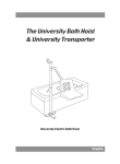
Sunrise Medical Limited High Street Wollaston West Midlands DY8 4PS England Tel: +44 1384 44 66 88 Fax: +44 1384 44 66 99 www.sunrisemedical.co.uk 374-70040 Issue 3 12 12 12 12 User Instruction Manual Oxford Mermaid & Ranger Bath Hoist Models: OXFORD MERMAID OXFORD RANGER OXFORD ELECTRIC MERMAID En gl ish OXFORD ELECTRIC RANGER Oxford Mermaid & Ranger Servicing, Repairs, Inspections And Testing Sunrise Medical Ltd has an established network of reputable distributors and dealers who will be pleased to handle all your purchasing, warranty, repair and maintenance enquires. Included with each lift is a prepaid Customer Satisfaction card. Please take the time to fill it in and return it to Sunrise Medical Ltd. Our products are guaranteed for a period of twelve months from the date of manufacture or twelve months from the date of purchase if commissioned by an authorised dealer. We recommend that all of our products are commissioned by your dealer and are supported by them for future servicing. The dealer or distributor operates the warranty programme, so it is important to keep a record of their name address and telephone number so they can be contacted should any problem arise. If you are in doubt where your lift was purchased, Sunrise Medical can trace the supplier if you quote the serial number of the lift. REMEMBER: Contact your distributor for purchases, Warranty, repairs, servicing and certified maintenance. Your distributor: 21 Oxford Mermaid & Ranger Oxford Mermaid & Ranger Technical Specification ELECTRICALSPECIFICATION Batteries Capacity Charger rated input Charger rated output Fuse - Lift 2 x 12 vdc Rechargeable, sealed, lead acid gel 3.2 Ampere/hours 230Vac 50/60 Hz 27.4/29.0 [email protected] 25A Fast Blow 1/4 x 1 1/4 Electric Shock Protection Charger - Class II Double Insulated Lift - Internal Power Source Degree of Shock Protection Charger - Type B Lift - Type B Mode of operation - 15% Intermittent Duty 20 Oxford Mermaid & Ranger Contents Introduction .................................................................................. page 3 Side and End fitting illustration .................................................... page 4 Assembly and installation instructions ........................................ page 5 Oxford Mermaid Electric illustration .............................................. page 6 Fitting dimensions ........................................................................ page 8 Installation of baseplate ................................................................ page 9 Wooden floor installations .......................................................... page 11 Mermaid setting up procedure ..................................................... page 12 Operating instructions ................................................................. page 13 Safety precautions ....................................................................... page 15 Charging instructions .................................................................. page 16 Maintenance schedule ................................................................. page 17 Daily check list ............................................................................. page 17 Scheduled maintenance, inspection and test ............................... page 17 Technical specification ................................................................ page 19 Servicing, Repairs, Inspections & Testing ................................... page 21 1 2 Oxford Mermaid & Ranger Oxford Mermaid & Ranger Technical Specification Safe Working Load (SWL) Highest position from base of seat Lowest position from base of seat Seat travel Width of seat Width between arms Mermaid Commode Ranger Manual 125 kgs 740mm 140mm 485mm 450mm 360mm 360mm Electric 125 kgs 715mm 140mm 485mm 450mm 360mm 360mm Mermaid Commode Ranger 395mm 395mm 430mm 395mm 395mm 430mm 410mm 430mm 410mm 430mm Depth of seat (front to back) Centres between mast and seat Max. seat turning circle (side fit) Mermaid Commode Ranger 850mm 810mm 840mm 850mm 810mm 840mm Max. seat turning circle Mermaid Commode Ranger 865mm 815mm 890mm 865mm 815mm 890mm 1000mm 1000mm 28.8kgs 39.9kgs ---------- 33.0kgs 44.0kgs 4.0kgs Minimum recommended clearance from mast to allow for leg room WEIGHTS Mermaid Ranger Battery pack TRANSPORTER (RANGER ONLY) Max width Max depth Max height Seat height Seat to footrest (adjustable) 610mm 560mm 610mm 510mm 430-480mm 19 Oxford Mermaid & Ranger Scheduled Maintenance, Inspection and Test (cont.) CHAIR SUPPORT CLAMP: Check the chair support clamp is correctly orientated as per the Setting Up instructions. Make sure the seat does not touch the side or bottom of the bath. Check the seat locks in the correct positions. CHECK the operation of the seat lock. SUPPORT ARM: Check the support arm has the safety screw in position and tightened. Check the seat is securely attached to the support arm and the fixing nuts and bolts are fully tightened. SEAT: Check the seat for splits or damage. Check the Mermaid seat for presence of nine safety plugs fitted to the seat moulding. (Lifts before December 1998) CASTORS: Check all castors are free running. Check fixing to the chair legs. Check brakes for correct operation. HANDCONTROL: Check the up and down switches of the handcontrol. Take the seat to the lowest position and confirm the operation of the bottom stop. Check the seat does not hit the bottom of the bath. Prevent the downward movement of the seat and check the power is switched off automatically. MOTOR UNIT: The motor should require no amintenance other than checking for correct operation and listening for unusual noise. BATTERIES: The batteries are housed in the power pack and should not require maintenance other than regular charging as detailed in the charging instructions. EMERGENCY STOP BUTTON: Check the operation and correct functioning of the emergency stop switch located on the rear of the power pack. EMERGENCY RAISE SWITCH: Check the operation and correct functioning of the rocker switch located on the motor unit. SAFETY LATCHES: Check the correct function of the safety latches on the Ranger Chair and the Ranger support arm. CLEANING: Clean with ordinary soap and water and/or any hard surface disinfectant. Harsh chemical cleaners or abrasives should be avoided as these may damage the surface finish of the lift. LOAD TEST: The load test should be carried out in accordance with the manufacturers test procedures. It is strongly recommended the testing is carried out by an authorised service dealer. CERTIFICATION: An authorised service dealer will issue a test certificate after satisfactory completion of the load test. This certificate will be valid for the period stated on the certificate. 18 Oxford Mermaid & Ranger About Your Lift Each lift is fully assembled, load tested and certified before being partially dismantled for packing. The installation of the lift cannot be factory tested so it is important to carry out the installation according to the guidelines provided in this manual. The packing consists of a strong, purpose built carton and is used for both export and domestic markets to ensure the safe arrival of the lift. A number of documents are supplied in a wallet packed with each lift and should be kept safely for future reference: Test Certificate User Manual Dealer Guarantee Card Customer Satisfaction Card The TEST CERTIFICATE is an important document and will be required for your insurance records. It is valid for six months and after it has expired the lift should be inspected and serviced for the following six month period. Servicing and periodic testing can be carried out by your supplier. Please ensure your lift is included in their maintenance schedule. The Oxford Mermaid & Oxford Ranger are suitable for Category C - Bath within the working parameters of the lifts specified in the TECHNICAL SPECIFICATIONS. The Oxford Mermaid & Oxford Ranger are suitable for patients in the SITTING position. The CE mark: The Oxford Mermaid & Oxford Ranger carry the CE mark and comply with the following EC directives: Medical Device Directive (93/42/EEC) EMC Directive (89/336/EEC) (Electrics only) Low Voltage Directive (73/23/EEC) (Electrics only) 3 Oxford Mermaid & Ranger 4 Oxford Mermaid & Ranger Maintenance Schedule for Oxford Bath Lifts Oxford Bath Lifts are designed to comply with BS EN ISO 10535: 1998: Hoists for the transfer of disabled persons - Requirements and test methods which recommends an annual service and test, but, in order to comply to the statutory provisions of 1998 No 2307 Health and Safety: The Lifting Operations and Lifting Equipment Regulations 1998. Sunrise Medical Ltd recommend a six monthly service and test. Statutory requirements for regular servicing may alter from country to country, please check your national regulations. Daily checks and a regular service, inspection and test will ensure a lift is kept in optimum safe working condition. A list of spare parts is available upon request. The LOAD TEST and certification should be carried out by qualified personnel or an authorised Service Dealer. Daily Check List Sunrise Medical Ltd strongly recommend the following checks are carried out on a daily basis and before using the lift. MAKE sure the handcontrol (electrics only) is plugged in firmly and the lift raises and lowers smoothly. MAKE sure the winding handle on manual lifts operates smoothly and the lift raises and lowers. CONFIRM the Mermaid is not sounding a low battery alarm (electrics only) when the handcontrol is operated. If the alarm sounds, DO NOT use and place the power pack on charge immediately. CHECK the operation of the emergency stop button (electrics only). CHECK the operation of the emergency raise button (electrics only). MAKE sure the seat is free to swing. CHECK the support arm safety screw is in place and tight. MAKE sure the castors on the Ranger chair are free to rotate and the brakes operate. Scheduled Maintenance, Inspection and Test Sunrise Medical Ltd recommend the following tasks are carried out by authorised service dealers only. FLOOR FIXING: Check the base plate fixing is sound and secure. Follow the test routine as detailed in the test manual. Wooden floors require inspection at more frequent intervals. MAST TO BASE: Check the four Nyloc nuts securing the mast to the base plate are fully tightened. Check also for signs of grease leakage between the mast and the base plate. 17 Oxford Mermaid & Ranger Charging Instructions for the Oxford Mermaid Electric Bath Lift The batteries are located in the power pack and are charged through a socket which also serves as the power supply socket for the lift. The socket is labelled POWER/CHARGING POINT. The battery pack on the Oxford Mermaid can be removed from the lift and charged independently or it can be charged while still attached to the lift. An additional battery pack can be supplied, if required, so that one pack can be on charge at all times. 1. Remove the power supply plug from the POWER/CHARGING POINT socket. The plug is removed with a straight pull. DO NOT twist the plug in the socket. The battery pack can now be removed from the lift for charging elsewhere or left in place for charging with the lift. To remove the battery pack simply pull the battery pack up by the handle on top of the pack and disengage the pack from the locating pins on the mast. Reverse the process for reconnection. 2. Connect the battery charger plug to the POWER/CHARGING POINT socket. The plug is indexed and can be fitted only one way. Make sure the red locking ring on the charging plug is in the unlocked position (Moulded pointer on the locking ring pointing to the Unlocked position). Connection is achieved with a straight push and then the locking ring can be twisted to Lock position. 3. Plug the charger mains plug into a suitable mains outlet and switch the mains supply ON. 4. Charging is fully automatic. The status of the charging is indicated by two LED indicators (see table below). Note: Even if the charger is left plugged in for extended periods it will not allow the batteries to overcharge. 5. To return the lift to service, switch OFF the mains supply, twist the locking ring on the charger plug to Unlocked and disengage from the POWER/CHARGING POINT with a straight pull. DO NOT pull on the cable to disengage the plug. The power supply plug can be reconnected with a straight push. DO NOT twist the plug in the socket. The lift is now ready for use. Charger Status Bulk charger mode Battery charged Battery reversal detected High temperature detected Short circuit Open circuit LED Indicators Yellow - static ON Green - static ON Yellow - flashing Yellow + Green flashing simultaneously Yellow + Green flashing alternately Yellow + Green static simultaneously The charging of Oxford electric lift is simple and straightforward, but it is important to follow the charging instructions closely. Please pay particular attention to the following points, it will help you avoid problems with discharged batteries. 16 KEEP the batteries fully charged. Place the lift on charge whenever it is not in use. The charger will not allow the batteries to overcharge. NEVER run the batteries completely flat. If the audible warning sounds, complete the lifting operation in hand and place the lift on charge. NEVER store the lift for long periods without regular charging throughout the storage period. ALWAYS make sure the mains power to the charger is switched off before connecting or disconnecting the charger to or from the lift. NEVER leave the charger plugged in to the lift with the mains power off. NEVER disconnect the charger plug by pulling on the cable. Oxford Mermaid & Ranger Assembly and Installation Instructions Models: Oxford Mermaid Oxford Ranger Oxford Electric Mermaid Oxford Electric Ranger Oxford bath lifts are supplied with a universal base plate. Concrete floors and wooden floors require different fixing kits. The lifts are packed with one type only and must be specified at the time of ordering. Mermaid and Ranger lifts can be fitted in two positions relative to the bath. The most common is the side fit, where the mast is fitted at the side of the bath and the end fit where the mast is fitted on the centre line of the bath at one end (see illustration page 4). The end fit option requires a different arm arrangement and must be specified at the time of ordering. PACKING: The Mermaid and the Ranger lifts are supplied in two cartons. Oxford Mermaid 1st carton: MAIN MAST ASSEMBLY (15 kgs) UNIVERSAL BASE PLATE (5 kgs) CONCRETE OR WOOD FLOOR FIXING KIT SEAT SUPPORT ARM (2.3 kgs) FOLD UP SAFETY ARMS (2) (2 kgs) WALLET CONTAINING DOCUMENTS Oxford Mermaid 2nd carton: SEAT ASSEMBLY (4.5 kgs) Oxford Ranger 1st carton: MAIN MAST ASSEMBLY (15 kgs) UNIVERSAL BASE PLATE (5 kgs) CONCRETE OR WOOD FLOOR FIXING KIT SEAT SUPPORT ARM (3 kgs) WALLET CONTAINING DOCUMENTS 5 Oxford Mermaid & Ranger OXFORD MERMAID ELECTRIC 6 Oxford Mermaid & Ranger Safety Precautions Please read and follow the safety precautions listed below. The operation and use of the Oxford patient lifts is simple and straightforward. Following these few basic safety precautions will make lifting operations easy and trouble free. ALWAYS plan your lifting operation before commencing. ALWAYS carry out the DAILY CHECK LIST before using the lift. ALWAYS familiarise yourself with the operating controls and safety features of a lift before lifting a patient. ALWAYS check the safe working load of the lift is suitable for the weight of the patient. ALWAYS carry out lifting operations according to the instructions in the user manual. NEVER disconnect or bypass a control or safety feature because it seems easier to operate the lift. NEVER force an operating or safety control. All controls are easy to use and do not require excessive force to operate. If a control is not working easily there will be a reason. Forcing will only strain or damge the lift and may compromise safety. DO NOT charge an electric hoist in a bathroom or shower room. DO NOT lift a patient unless you are trained and competent to do so. YOUR lift is for patient lifting. DO NOT use it, or allow it to be used, for any other purpose. 15 Oxford Mermaid & Ranger Operating the Mermaid and Ranger Bath Lifts (cont.) SWINGING THE SEAT: To rotate the seat, fully lift the locking lever. With the lever fully UP, the seat is unlocked and free to rotate 360 degrees. When the locking lever is fully DOWN, the seat will lock in one of four positions. If the lever is pushed down at an inermediate position it will automatically engage when it encounters the next locking position. Do not rely on the positional lock to halt the patients swing as this can cause high loading on the latch and may eventually lead to failure. RANGER MODEL: The Ranger differs from the Mermaid and requires some additional instructions. The Ranger chair is made in two assemblies, a wheeled base and a seat with armrests. The halves of the complete chair are connected with a simple latch located at the rear of the seat. The chair is attached to the bath lift as follows: 1. The chair support arm of the lift has a hook and latch device similar to the one connecting the seat to the wheeled base. The support arm hook must be engaged with the cross bar at the top of the seat. The latch will engage automatically and prevent accidental disengagement. 2. The seat can now be lifted off the wheeled base by operating the seat latch, which holds the seat to the wheeled base, and raising the support arm of the lift with the handcontrol or winding handle. The seat will be elevated with the support arm and the wheeled base will remain behind. 3. To reconnect the seat to the base, lower the seat with the handcontrol or winding handle back onto the wheeled base with the lower safety latch in approximately the right position. The seat will lock automatically as it is lowered. When the seat latch is engaged, disengage the latch on the chair support arm and continue to lower. The support arm will drop away from the seat and can be swung away to one side. Check full engagement of the seat latch. The patient can now be transported to another location. IMPORTANT NOTE: When the seat is fully secured to the transporter, it is important to ensure the upper safety latch is completely disengaged. Damage to the rear castors will occur if the bath lift continues to be lowered with this latch engaged or partially engaged. The safety locking system has been designed to be very visible and very obvious in operation - double check the latches have engaged or disengaged correctly. NOTE: Sunrise Medical recommend a few dry runs to familiarise users with the operation of the transporter chair and bath lift. EMERGENCY RAISE: This facility will raise the seat should the lift fail to rise with the handcontrol. It is for emergency use only and should not be used for routine raising. The switch is locted on the power unit cover. 14 Oxford Mermaid & Ranger Oxford Ranger 2nd carton: RANGER SEAT ASSEMBLY (6 kgs) SAFETY ARMS (2) (2 kgs) TRANSPORTER CHASSIS (9.4 kgs) Oxford Electric Mermaid 1st carton: MAIN MAST ASSEMBLY (15 kgs) UNIVERSAL BASE PLATE (5 kgs) HANDCONTROL POWER PACK CHARGER CONCRETE OR WOOD FLOOR FIXING KIT SEAT SUPPORT ARM (2.3 kgs) FOLD UP SAFETY ARMS (2) (2 kgs) WALLET CONTAINING DOCUMENTS Oxford Electric Mermaid 2nd carton: SEAT ASSEMBLY (4.5 kgs) Oxford Electric Ranger 1st carton: MAIN MAST ASSEMBLY (15 kgs) UNIVERSAL BASE PLATE (5 kgs) HANDCONTROL POWER PACK CHARGER CONCRETE OR WOOD FLOOR FIXING KIT SEAT SUPPORT ARM (3 kgs) WALLET CONTAINING DOCUMENTS Oxford Electric Ranger 2nd carton: RANGER SEAT ASSEMBLY (6 kgs) SAFETY ARMS (2) (2 kgs) TRANSPORTER CHASSIS (9.4 kgs) Check the contents of the cartons carefully, if any parts are missing or damaged contact your supplier immediately. 7 Oxford Mermaid & Ranger 8 Oxford Mermaid & Ranger HEIGHTADJUSTMENT OF THE SEAT (cont.) Take care not to allow the seat to rotate out of alignment, slide the clamp up to its maximum position and lightly retighten.Using the handcontrol, wind the seat to its lowest position (until the bottom stop is encountered). Slacken the clamp again and carefully slide it down the mast until the bottom of the seat is 3 - 5 cms from the bottom of the bath. Lightly tighten the clamp and recheck the alignment of the seat in the bath. FULLY tighten the clamp Allen screw. The Allen screw is high tensile and must be fully tightened to effect a positive lock. If the seat hits the bath before the end stop is encountered, additional steps must be taken to avoid damage to the bath. The Memaid and Ranger have been designed to be comparible with a wide range of bath design but the installer may encounter baths which do not conform to normal design. If the seat bottoms out before the end stop on the lift is encountered, this indicates the bath is elevated higher than normal. Firstly, check the seat is wound up to the highest position clears the top edge of the bath. Remember a loaded lift will be lower than an unloaded one, so make sure there is sufficient clearance. If the seat satisfactorily clears the top edge of the bath then a stop collar can be used to set the lowest position. If the seat does not clear the top edge of the bath then the lift must be fitted with a spacer at the bottom of the mast. Contact Sunrise Medical Ltd for the supply of either of these items. Operating the Mermaid and Ranger Bath Lifts MERMAID MODEL: The Mermaid range of bath lifts are designed to be simple and safe to use. Carefully follow these simple instructions to ensure trouble free operation. RAISING & LOWERING: The patient seat is raised or lowered on the manual versions of the bath lifts by use of the winding handle on the top of the lifting column, anticlockwise for lift and clockwise for lower. The limit of travel is governed by positive stops built into the mechanism. It will be very obvious to anyone operating the lift when these stops are encountered. NOTE: Do not attempt to force the winding handle past the stops as this will damage the mechanism and will lead to expensive repairs. ELECTRIC MERMAID The patient seat is raised or lowered on the electric versions of the bath lifts by the handcontrol which is plugged into the control unit at the top of the main column. Pressing the buttons marked with directional arrows will raise or lower the seat. The limit of travel is governed by positive electronic stops built into the circuitry. NOTE: Repeated activation of the handcontrol buttons once the end stops are encountered will damage the control circuitry and shorten working life. 13 Oxford Mermaid & Ranger Testing of Installation With the base plate firmly installed, place the mast back onto the base plate studs and fully tighten down the four nuts. IMPORTANT: It is strongly recommended the installation of the base plate is load tested before the Mermaid is put into use. Following the recommendation in BS 5827 the installed lift should be load tested to 125% of the safe working load. In the case of the Mermaid and Ranger the test load is 157 kgs. This load is applied to the centre of the seat. DO NOT ignore this test. If in doubt contact your supplier. IMPORTANT NOTE: Please take into consideration the turning radius required for clearance of the patients knees from radiators, walls or other obstructions. A minimum radius of 1 metre from the centre of the mast is recommended. SETTING UP: The Mermaid and Ranger models have a setting up procedure which must be followed to ensure the lift operates safely and causes no damage to the bath or fitments. SEAT LOCKING SYSTEM: The seat locking system engages at four, 90 degree positions and is operated by a locking lever situated on the main mast. With the lever fully UP, the seat is unlocked and free to rotate 360 degrees. When the locking lever is fully DOWN, the seat will lock in one of the four positions. If the lever is pushed down at an intermediate position it will automatically engage when it encounters the next locking position. DO NOT use this automatic engagement to stop the swing of a loaded seat. If latch is used repeatedly to stop a moving loaded seat, the latch will be damaged and replacement required. SETTING THE FOUR POSITIONS RELATIVE TO THE BATH: Check the position of the seat in relation to the bath. If the seat is not central in the bath cavity its position can be adjusted as follows. Slacken the seat support clamp by loosening the Allen headed screw on the side of the clamp. This will allow the clamp, seat and seat arm to rotate. Engage the seat locking and swing the seat until it is in line with the centre line of the the bath. Lightly tighten the Allen headed screw. Release the seat lock and rotate the seat through 90 degrees. This will place the seat in the normal position at the side of the bath. If this is the only adjustment required FULLY tighten the Allen headed screw. If height adjustment is required leave the Allen screw lightly tightened and go on to next section. HEIGHT ADJUSTMENT OF THE SEAT: The seat height must be carefully set to avoid damage to the bottom of the bath in normal use. With the seat aligned with the centre line of the bath, slacken the seat clamp again. 12 Oxford Mermaid & Ranger Assembly of Mermaid & Ranger 1. Remove all the parts from the carton and place on the floor, taking care to protect the finish from damage. SAFETY NOTE: Some of the parts are heavy and will need to be lifted with care. You may need assistance with the heavier assemblies. 2. Before commencing assembly establish the seat position required. The drawing on page 4 will help clarify whether a left, right or end fit arm is required. 3. Having established the position of the seat, assemble the Mermaid seat and safety arms to the chair support arm. These components are fixed together with two stainless steel nuts and bolts. Assembly and Installation Instructions MAST POSITIONING Baths vary greatly in shape and size. It is very important to establish the exact position of the mast in relation to the particular bath. IMPORTANT NOTE: The lift seat may damage the sides or back of the bath if it is incorrectly fitted. 1. Place the base plate on the floor in the approximate final position. Locate the mast onto the four base plate fixing studs. Lightly tighten down the nuts onto the studs. 2. Connect the seat and arm to the Mermaid column. Secure the seat arm with the safety screw. The whole unit will require supporting during this operation. 3. Position the seat in the bath cavity and move the whole assembly until the seat is in the optimum position. This is with the seat on the centre line of the bath with clearance both sides and as far back as the design of the bath will allow. Make sure there is clearance under the seat and make allowance for some downward movement when the seat is loaded. This will avoid damage to the surface of the bath. 4. With the lift in the optimum location, mark the position of the base plate fixing holes. Check the area for hidden services. Remove the base plate from the column, this will make it easier to handle while fixing. Installation of the Base Plate CONCRETE FLOORS: Establish with your architect the structural integrity of the concrete floor, bearing in mind the stresses imposed by the Mermaid. In brief, a sound floor of at least 120 - 150mm thickness of good concrete is ideal. An element of screed is acceptable, as long as the expanding section of the fixing bolts are in sound conctrete. Drill three 16mm diameter x 125mm deep holes in the positions marked out from the base plate. Locate the base plate over the holes and insert the expanding bolts. NOTE: The expanding bolts which are supplied with the lift are designed to be fitted fully assembled, DO NOT take them apart. Tighten the bolts fully with the Allen key supplied. 9 Oxford Mermaid & Ranger Assembly and Installation Instructions CONCRETE FLOORS (cont) IMPORTANT NOTE: Not all concrete floors are constructed in a manner which allows for this type of fixing. Floors which are constructed from precast beams with block infill do present a problem which cannot be overcome easily. If your floor is of this construction, or you suspect it may be, consult an architect for guidance. WOODEN FLOORS: Establish with your architect the structural integrity of the wooden floor, bearing in mind the loading and stresses imposed by the lift. There are many forms of wooden floor construction. The following information should be regarded only as guidelines for your builder or carpenter, whose knowledge and skill will be an important factor in the secure and safe installation of the lift. Not all wooden floors are constructed in such a way to allow for lift mounting without extensive strengthening. If in any doubt consult an architect. For the most common floorboard construction, an underfloor bracing kit is supplied as a standard pack. It may not suit all applications. See the illustration on the following page. If the location of one or more of the base plate fixing holes coincide with a joist, then a heavy wood screw or coach bolt can be used in conjunction with the bracing kit. Additional holes in the base plate allow for extra location points on wood floors. Floorboards in the immediate area ot the base plate should be secured to the joists with heavy wood screws. It is important that fixing should be carried out on sound and suitable floors only. Chipboard and similar lightweight floors will need to be reinforced locally. The advice of an architect should be sought to establish the amount of reinforcing necessary. Joists can be reinforced by fixing strengthening sections alongside and between existing joists. Floors can be strengthened by additional local fixing to the existing joists and/or by using a heavy marine plywood inset. If in doubt, seek professional advice. 10 Oxford Mermaid & Ranger Wooden Floor Installation Kit Two steel bars are provided for the safe installation of the bath lift to wooden floors. The bars should be used as follows: All three holes in the base plate should be used, with one bar spanning either A or B and the other bar bolted through the third hole. Three countersunk steel screws are supplied for this purpose. Ideally each bar should span as many floorboards as possible (usually three). Whether a bar will span either A or B will be decided according to the direction and position of the joists in the area chosen for siting the Bath Lift. Access is normally achieved by removing a section of floorboard adjacent to the fixing area large enough to allow the insertion and positioning of the bars. All floorboards taking any part of the load should be securely fastened down to the joists with 4 (100mm) countersunk wood screws. The final installation should be tested according to the manufacturers recommendations. 11