1
S3C44B0X RISC MICROPROCESSOR
ARM INSTRUCTION SET
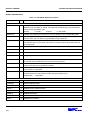
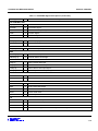
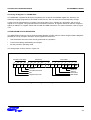
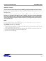
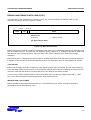
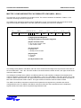
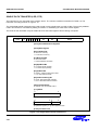
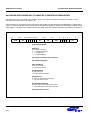
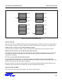
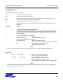
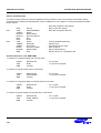
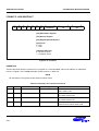
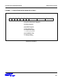
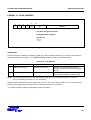
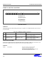
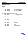
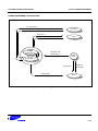
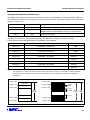
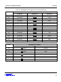
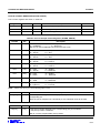
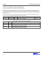
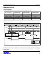
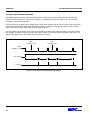
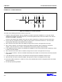
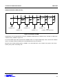
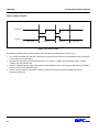
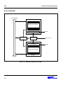
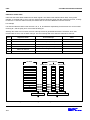
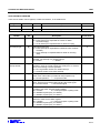
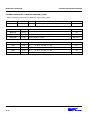
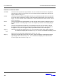
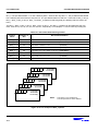
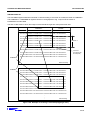
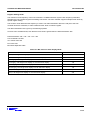
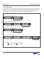
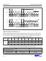
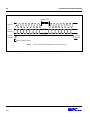
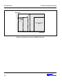
FORMAT 12: LOAD ADDRESS
15
14
13
12
11
1
0
1
0
SP
10
8
0
7
Word 8
Rd
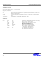
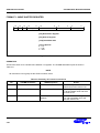
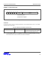
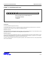
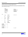
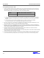
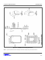
[7:0] 8-bit Unsigned Constant
[10:8] Destination Register
[11] Source
0 = PC
1 = SP
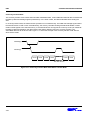
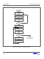
Figure 3-41. Format 12
OPERATION
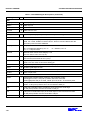
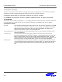
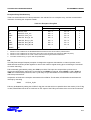
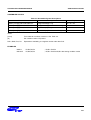
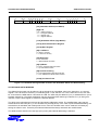
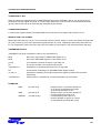
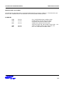
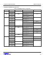
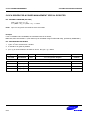
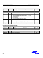
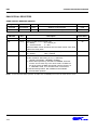
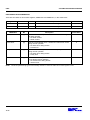
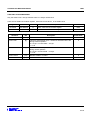
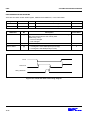
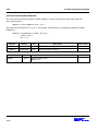
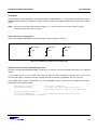
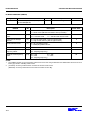
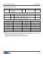
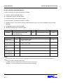
These instructions calculate an address by adding an 10-bit constant to either the PC or the SP, and load the
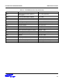
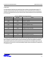
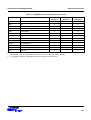
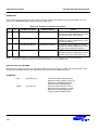
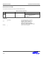
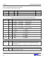
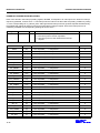
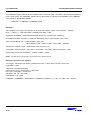
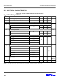
resulting address into a register. The THUMB assembler syntax is shown in the following table.
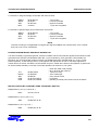
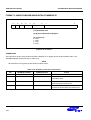
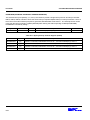
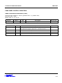
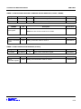
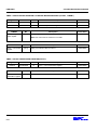
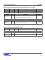
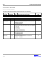
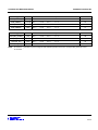
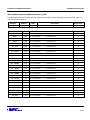
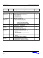
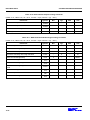
Table 3-19. Load Address
L
THUMB assembler
ARM equivalent
Action
0
ADD Rd, PC, #Imm
ADD Rd, R15, #Imm
Add #Imm to the current value of the
program counter (PC) and load the result
into Rd.
1
ADD Rd, SP, #Imm
ADD Rd, R13, #Imm
Add #Imm to the current value of the stack
pointer (SP) and load the result into Rd.
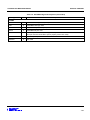
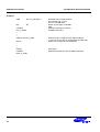
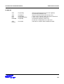
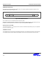
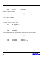
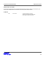
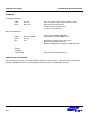
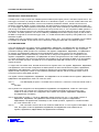
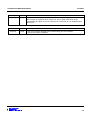
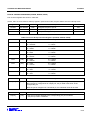
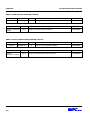
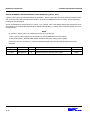
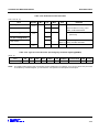
NOTE: The value specified by #Imm is a full 10-bit value, but this must be word-aligned (ie with bits 1:0 set to 0)
since the assembler places #Imm >> 2 in field Word 8.
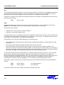
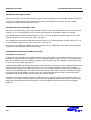
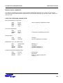
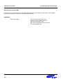
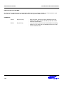
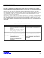
Where the PC is used as the source register (SP = 0), bit 1 of the PC is always read as 0. The value of the PC
will be 4 bytes greater than the address of the instruction before bit 1 is forced to 0.
The CPSR condition codes are unaffected by these instructions.
3-91