1
LAB2: Programming with the LED and LCD
Due May 7, 2009 – Rev B
The Embest User Guide is available under “Links” on the class website or on
CD1.
1. Eight-segment LED display
Get familiar with the eight-segment LED and its control.
1) Architecture
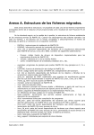
The 7-segment LED (8 segments including the decimal point) consists of 8 light emitting diodes (LED).
A 7-segment LED can display all the numbers and some of the English alphabetic characters.
2) Work Principles
Multi-segment LEDs can have either a common anode or a common cathode. “Common anode” means
that all the anodes of the LEDs are tied together while the cathodes are used for selective illumination.
“Common cathode,” then, means all the cathodes of the LEDs are tied together. The common electrode
is then usually connected directly to ground or Vcc. Using the common anode type, when the control
signal for one segment is low, the related LED will be lit. When a character needs to be displayed, a
combination of LED segments must be on. Using the common cathode type, the LED will be on when
the control signal is high. The following is the commonly used character segment coding for the
S3CEV40:
a
Vcc
f
c
e
d
dp
Q7
Q6
Q5
Q4
Q3
Q2
Q1
Q0
74HC573
b
Fig 1-1: LED segments. Resistors are not shown between the LED and 74HC573.
The 74HC573 is simply an 8-bit latch (1 byte memory) that stores the value of the least significant byte
written to it. Those bit values are connected directly to the cathodes of the LED segments.
The LED is described in section 3.4.2 of the Embest User Guide. Note that it uses “CS6” (chip select 6)
to address the latch. The chip select lines are described in section 3.5.1.
3) Using Pointers in C
If you are not familiar with pointers, you should refer to the various tutorials on the web or consult a
textbook on C programming. C programming is a prerequisite of this class. The instructors are happy to
help you, but it is not the intent of this lab to teach pointers. This section is only for review.
A pointer is an address to a memory location. Anything that resides in memory has an address pointing
to it. Variables reside in memory, as do arrays, and functions. Therefore, variables, arrays and functions
can all have pointers declared that point to them. For embedded systems, memory-mapped I/O and
other hardware components can also have pointers declared that point to them since they have
addresses associated with them.
When you declare a variable, for example, with the statement:
int var;
/* declare an integer variable */
you are setting aside memory for the variable “var” with the number of bytes reserved for an “int”.
To find out the address of these reserved bytes, we use the pointer operator “&”, which returns the
address (the “pointer”) to the variable:
&var;
/* returns the address of var */
It is also possible to declare a “pointer variable” with the statement:
int *varPointer;
/* declare a pointer variable */
The “*” character indicates you are declaring a pointer variable for an address that points to an int.
varPointer is a variable that you can use to hold an address that points to an int. For example, you
can use it to hold the address (the pointer) to var with the statement:
varPointer = &var;
/* varPointer now points to var */
To read the value of var, you can use the “value of” operator, “*”, to get the value that a pointer points
to:
*varPointer;
/* returns the value of var */
It is important to realize that when you declare a pointer variable you are not actually reserving memory
to hold a value. You must always initialize the pointer to point to some valid region of memory before
you try to access the value of the pointer. For example, the following code will cause an error (though
the effects of the error may not be immediately apparent):
int *varPointer;
/* declare a pointer variable */
*varPointer = 10; /* set the value of varPointer to 10 */
The code above is erroneous because varPointer is not initialized to point to a valid memory
location. It may be pointing to something, but you don’t know what. Therefore, you are writing the
value 10 to some unknown location.
If you declare an array variable, for example, with the statement:
int varArray[10];
you can retrieve the address of the beginning of the array in one of two ways:
varPointer = varArray;
/* get addr of varArray */
varPointer = &varArray[0];
/* get addr of varArray[0] */
In both cases, varPointer points to the first element of the array. Likewise, if you declare a function,
for example, with the following code fragment:
int func5()
{
return (5);
}
you can retrieve the address of the function with just its name:
varPointer = (int *) func5; /* get addr of func5() */
In the case above, varPointer is declared as a pointer to an int, not a pointer to a function that
returns an int. Therefore, it is proper to type cast the pointer-to-a-function-that-returns-an-int to a
pointer-to-an-int before storing it in a pointer-to-an-int variable.
4) Operation Steps
1.) Look up the memory map for the S3CEV40 in section 3.5.2 of the Embest User Guide. Find the
address of the “8-SEG” LED. Note the peculiar addressing. Consider what this might mean. Test your
hypotheses by connecting to the remote board (not the SIM_ARM7), entering values into the command
window, and watching the result on the 8-segment LED. To enter values into the command window,
use the “memwrite –e 0xAAAAAAAA 0xDD” command, where 0xAAAAAAAA is the 32-bit address
you want to write and 0xDD is the data you want to put there. (The “-e” option uses big endian mode
to write data, permitting byte values to be written conveniently. If you use 32-bit data values in the
command, 0xDDDDDDDD, you can drop the “-e” option.) Include in your report a paragraph or
two explaining the listing of the “8-SEG” in the memory map and what you did with the
S3CEV40 to test your explanation. What makes it peculiar? Why is it designed this way? Are
there other parts of the User Guide that validate your explanation? How did you test your
hypotheses? Why are we using big endian mode?
For extra credit, try using the memory editor window instead of the command window. Describe
the behavior you see. Explain the behavior observed on the LED when you try to modify the
LED via the memory editor.
2.) Prince, the pop musician, as the result of a dispute with his record label, elected to formally change
his name to an unpronounceable symbol. Using the memory editor of the S3CEV40, create a unique
symbol for your group and take a picture of it on the S3CEV40. Include the picture in your lab
report and include the bit pattern that defines it. (If your camera has a close-up mode, usually
indicated by the flower symbol, please use it.) Experiment with other bit patterns until you are
confident you can create any possible character.
3.) With the knowledge you have gleaned from the User Guide, write a C program of your own that
sequentially lights each individual segment of the 8-segment LED, one segment at a time with a brief
pause between each segment. This sequence should repeat indefinitely. You must carefully comment
all your programs so the meaning and purpose of each section or subsection is clear. Include this
source file as an appendix in your lab report. When in doubt, over-comment or risk losing
points.
For comments, I expect to see a header at the top with your group names, file name, and a description
of what the file does, with any dependencies. I also expect to see a brief header before every function
explaining what the function does, how it does it (if appropriate), the meaning of its arguments, and any
output. Finally, I expect to see meaningful function and variable names and meaningful comments
liberally sprinkled throughout the code. Comments such as i++; /* inc. the variable */ are
not meaningful.
A subtlety in embedded systems is that hardware can force certain read/write behavior. For example,
hardware can dictate that certain memory locations are byte-accesses or half-word-accesses only, as
opposed to up to the control of the programmer (by variable declaration). In your C code, “explore” the
behavior of the LED register. Determine if this register has size limitations on read/write accesses. In
your lab report, include a description of a few paragraphs of what you determined and how you
determined it.
When Creating a C program from scratch for an embedded system, keep in mind there are certain
preliminaries required to “bootstrap” the program. (For example, the linker needs to be able to find the
“main()” procedure.) To do this, the board manufacturers have provided some initialization code and
linker instructions. The initialization code is an assembly file named 44binit.s and the linker
instructions are contained in the file ram_ice.ld.
Create a new workspace, then create a new file. Enter your code into this file, then remember to include
your new file into your project. Set your project settings as instructed previously (including setting the
GNU assembly tools under “Build Tools”). Include the 44binit.s source file in your project, as
well. You can include it in the source file or create a new folder called “common.” Additionally, under
the “Project/Settings” menu item, select the “Linker” tab. Under the “General” drop-down menu option,
add ram_ice.ld as the “Linker script file” as shown below.
Fig 1-2: Configuring the linker script.
Next, select the “Image Entry Options” drop-down menu option and select 44binit.o as the “Select
entry file” option, as shown below.
Fig 1-3: Configuring the linker entry file.
4.) Write another C program of your own that creates the sixteen hexadecimal characters on the LED
display, in sequence, with a brief pause between each character. This sequence should repeat
indefinitely. You must carefully comment all your programs so the meaning and purpose of each
section or subsection is clear. Include this source file as an appendix in your report. When in
doubt, over-comment or risk losing points.
Reminder:
1. Check the project setting. Go to Project->Settings, open the Linker tab, then select the “Add
library Searching Path”, change the directory as shown in Fig 1-4. Take care that the
c:\EmbestIDE is the folder where you installed the software, if you install in some other
directory, change it to your directory.
2. Go to Project->Settings, open the Debug tab, at the bottom you will see Command script.
Change the Command script path to the file “common\ev40boot.cs”. Configure as in Fig 1-5.
Fig 1-4. Linker setting
Fig 1-5. Configuring the command script.
2 External Interrupt Experiment
Get familiar with the interrupt register of S3C44B0X, the related registers and the principle of ARM
interrupt service routines (ISR).
1). Interrupt Controller Operation
1.1) Interrupt Modes
The interrupt mechanism is an important hardware facility of nearly all modern CPUs. An interrupt is
an event-based change in the flow of control, as opposed to a software-based change in the flow of
control (such as a branch instruction). We generally think of interrupts as a hardware signal (logic line)
that causes the CPU to stop what it is doing and start doing something special. Somewhat like a tap on
the back. The ARM processor has 26 interrupts which can each be individually set in one of two
interrupt modes: fast interrupts (FIQ) and normal interrupts (IRQ). We will not worry about the details
here. They are described in the user manual for the S3C44B0X CPU. For our purposes, we will always
use IRQ mode.
1.2) Interrupt Configuration
The interrupts can be individually configured by a series of registers. Generally speaking, each
interrupt is individually configured by a corresponding bit in each of the 32-bit registers. Interrupt 0
corresponds to bit 0, interrupt 1 corresponds to bit 1, etc. Usually, the 6 most significant bits are not
used.
1.3) Interrupt Registers
1.3.1 INTCON (interrupt control)
INTCON appears at address 0x01E00000 and disables interrupts. Bit0 disables all FIQ, bit1 disables all
IRQ, and bit2 disables the interrupt vector table for IRQ. 1 = disable, 0 = enable.
1.3.2 INTPND (interrupts pending)
INTPND appears at address 0x01E00004 and is a read-only register that indicates all the interrupts that
are pending.
1.3.3 INTMOD (interrupt mode)
INTMOD appears at address 0x01E00008 and controls the mode (IRQ or FIQ) of each interrupt, bit by
bit. A value of 0 sets the corresponding interrupt to IRQ, while 1 sets the interrupt to FIQ.
1.3.4 INTMSK (interrupt mask)
INTMSK appears at address 0x01E0000C and masks individual interrupts. A mask temporarily hides
the interrupt. If the corresponding bit value is 1, the interrupt is masked. Bit26 is a global mask of all
interrupts. If an interrupt is masked when it occurs, nothing will happen. However, the interrupt event is
remembered so when the mask is cleared, the interrupt will happen.
1.3.5 IRQ_ISPC (interrupt service pending control)
IRQ_ISPC appears at address 0x01E00024 and allows the clearing of pending IRQ interrupts on a
bit-by-bit basis. It is necessary for all interrupt service routines to clear the interrupt as part of the
servicing of the interrupt. Writing a 1 to the corresponding bit clears the interrupt.
1.3.6 FIQ_ISPC (interrupt service pending control)
FIQ_ISPC appears at address 0x01E0003C and allows the clearing of pending FIQ interrupts on a
bit-by-bit basis. It is necessary for all interrupt service routines to clear the interrupt as part of the
servicing of the interrupt. Writing a 1 to the corresponding bit clears the interrupt.
1.4) Interrupt Service Routines
When the CPU stops what it is doing as the result of an interrupt, the “something special” that it starts
doing is determined by the “interrupt service routine.” The interrupt service routine is the subroutine
that needs to run when the interrupt occurs. When using vectored interrupts, the interrupt vector table is
the structure that associates different interrupt service routines with different interrupts. The vector
table starts at address 0x0C7FFF00 and consists of about 32 4-byte addresses that point to subroutines
that are the interrupt service routines.
2) Exercises
Your assignment is to write two C functions: intr_init() and ISR_Eint4567() plus the
main() function that uses them using the stubs provided below. The main function will initialize the
interrupts (calling intr_init()) and then wait in an infinite loop. Button SB2 will trigger external
interrupt source EINT6 which will cause an interrupt service routine to display the characters 0 to F on
the 8-segment LED with a pause between each display value. Each button press (interrupt) should
cause the LED to display each value once. Pressing the button again should cause the display of the
values on the LED again.
External interrupts 4,5,6, and 7 all share the same hardware interrupt line. Therefore, there is an extra
register, EXTINTPND, that indicates which of these four interrupts is pending. EXTINTPND is a
read/write register that appears at address 0x01D20054 and bit0 corresponds to external interrupt 4
(EINT4), bit1 to EINT5, bit2 to EINT6, and bit3 to EINT7. The interrupt service routine for these
interrupts must clear the bit in EXTINTPND then clear the bit in INTPND as part of servicing the
interrupt.
EINT4/EINT5/EINT6/EINT7 correspond to bit21 in the registers and the 29th vector in the vector table
(0x74 bytes from the base).
Interrupt service routines are special. They must be specially designated to the compiler as interrupt
service routines. Letting the compiler know which routines are ISRs is not standardized and is compiler
dependent. For the GNU tools, you must set an “attribute.” For example, if your ISR has the function
prototype:
void my_isr(void);
you would add the attribute:
void my_isr(void) __attribute__ ((interrupt ("IRQ")));
in the function prototype at the top of your source code.
The keyword “volatile” in C is used to prevent the compiler from optimizing away your variable
reads and writes. This tells the compiler that the value might change on its own. Turn in your
commented C code.
3. Interrupt Initialization
/*******************************************************************
* name: intr_init()
* func:
*******************************************************************/
void intr_init(void)
{
volatile int *PconG = (volatile int *)0x01D20040;
volatile int *PupG = (volatile int *)0x01D20048;
volatile int *extInt = (volatile int *)0x01D20050;
/* add your variable declarations here */
/* Clear the pending interrupt bits here, before enabling */
/* configure the interrupt and enable the interrupt here */
/* set the EINT interrupt service routine in the vector table here */
/* Some special configuration for PORT G is required below.
Do not change this part */
*PconG = 0xffff; // set port G as external interrupt EINT7~0
*PupG = 0x00;
// enable the pull up resistors
*extInt = *extInt|0x22220020; // EINT4/5/6/7 falling edge mode
/* Clear the pending interrupt bits again here */
}
4. Interrupt Service Routine
/*******************************************************************
* name: ISR_Eint4567
* func:
*******************************************************************/
void ISR_Eint4567(void)
{
/* put your variable declarations here */
/* Make sure it is EINT6 here */
/* Display the values 0 – F here with brief pause between */
/* Clear the pending interrupt bits here */
}
3 LCD Display
In this section, you are requested to design a program to display some strings on the LCD screen using
vendor-supplied drivers of the type that often come with hardware. The source code was provided with
some strings missing, but you have the instructions to write some code to fill it.
1). Show your name and initials on the LCD
First of all, download the files lcd.c and lcd.h. Use the Embest IDE to create a new workspace,
with the name LCD_String. Configure it appropriately as described above in section 1 and in Lab 1.
Add lcd.c to your project and open it. Scroll down and you will find the function lcd_Test().
Enter your code in this function. Follow the instructions, creating your own code to display some
characters and sentences on the LCD screen.
The function Lcd_Init() is used to initialize the LCD controller. Lcd_Clr() and
Lcd_Active_Clr() are used to clear the LCD screen buffers (both virtual and active). So before
you use the LCD screen, you should call them first. And you need to understand in the function
Lcd_Init(), the different scan approaches with different registers. For more information please
refer to http://www.soe.uoguelph.ca/webfiles/rmuresan/EmbeddedSystemsAndLabsForARM-V1.1.pdf
at Chapter 5 Human Interface Labs.
The S3C44B0X LCD controller can generate 16 gray levels using frame rate control (FRC). The
FRC characteristics may cause unexpected patterns in gray levels. These unwanted erroneous patterns
may appear briefly on the LCD or at lower frame rates.
The next step is using the provided instruction to look up your name in the ASCII Reference in fig.3-1,
and follow the instructions below to program your own code to display your name on the screen, take a
picture of the result, hand in your code and the picture. Your grade will be based on your files.
Before you start, you should understand that the LCD screen does not display characters directly. It is a
graphic display device and is pixel oriented. It takes many pixels to form a character, while any
particular character can be displayed via many different pixel organizations (or fonts). Since there are
16 gray levels, each pixel takes one nibble or half of a byte. In this experiment, the 6x8 ASCII code
bit-mapped table is provided in file AscII6x8.c, and function g_auc_Ascii6x8[] is used to search the
table for the character you want. Because each byte (such as ‘0x00’) has 8 bit values, we need to
process bit-by-bit to display the character. Part of the ASCII table is shown as follows:
0x00,0x3E,0x51,0x49,0x45,0x3E,0x00,0x00, /*0*/
0x00,0x00,0x42,0x7F,0x40,0x00,0x00,0x00, /*1*/
0x00,0x42,0x61,0x51,0x49,0x46,0x00,0x00, /*2*/
0x00,0x21,0x41,0x45,0x4B,0x31,0x00,0x00, /*3*/
0x00,0x18,0x14,0x12,0x7F,0x10,0x00,0x00, /*4*/
0x00,0x27,0x45,0x45,0x45,0x39,0x00,0x00, /*5*/
0x00,0x3C,0x4A,0x49,0x49,0x30,0x00,0x00, /*6*/
0x00,0x01,0x01,0x79,0x05,0x03,0x00,0x00, /*7*/
0x00,0x36,0x49,0x49,0x49,0x36,0x00,0x00, /*8*/
0x00,0x06,0x49,0x49,0x29,0x1E,0x00,0x00, /*9*/
Fig 3-1. ASCII reference
Note that the 6x8 ASCII codes use 8 bytes to represent (8x8). This is because extra blank pixels are
embedded in the 8x8 array to allow for constant spacing of the characters.
Exercise 1: Use the standard character display routines provided in lcd.c to display the names
of all group members. Take a picture of the result on the LCD screen and include the code in
your report. Discuss the need for the Lcd_Dma_Trans() function call at the end of
Lcd_Test().
A display function has been created with the following function prototype:
void LCD_3231(void);
This function is provided in the file LCD3231.o.
Exercise 2: Link this file into your code and call the function. Take a picture of the LCD screen
and include in your report.
Exercise 3: Using the standard function Lcd_DspAscII8x16() as a guide, create a new function:
void Lcd_AscII8x16zoom(INT16U x0, INT16U y0, INT8U ForeColor, INT8U * s, INT8U scale);
that provides a scale factor from 1 to 4 to display larger characters. Display the initials of each member
of your group with this new routine at different scales. (If you are in a group by yourself, display your
own initials with at least two different scale factors.) Include a picture of the LCD screen and your
code in your report.
For the final exercise, you will create a custom proportional font that is variable-with instead of the
fixed-width font of the standard routines. You will also write directly to the LCD screen buffer,
obviating the need for the Lcd_Dma_Trans() function.
We use the LCD_Show() function to display the character. The LCD_Show() function writes
directly to the LCD screen without using the DMA method. DMA method is one way that copies the
virtual LCD screen (memory buffer) to the actual LCD screen without using many CPU cycles. The
virtual screen is the memory section which has the same size as the actual LCD screen.
#define LCD_Show(x, y, c)
\
(*(INT32U *)(LCD_ACTIVE_BUFFER + (y) * SCR_XSIZE / 2 + ((x)) / 8 * 4)) = \
(*(INT32U *)(LCD_ACTIVE_BUFFER + (y) * SCR_XSIZE / 2 + ((x)) / 8 * 4)) & \
(~(0xf0000000 >> ((((x))%8)*4))) |((c) << (7 - ((x))%8) * 4)
The next step is to Look at the LCD_Test() function. Follow the instructions to program the
code which can display your custom initials on the screen. The structure of the code is as follows:
***********************************************************************
void LCD_Test(void)
{
/* initialize LCD controller here */
////////////////////////////////////////////////////////////////////
///////////////////////////////////////////////////////////
INT8U ucTemp;
INT32U i,j,m,z;
/* 1.Define an INT8U array, which contains your name in hexadecimal numbers,
using z to count the size of the array */
for(m=0;m<z;m++)
{for( i=0; i < 8; i++ )
{
/* 2. ucTemp contain the result of calling function g_auc_Ascii6x8[].
Reminder: the ASCII table have 8 values for each ASCII code. So you should
multiply 8 then add the offset to visit value for each ASCII code. */
for( j = 0; j < 8; j++ )
{
if( (ucTemp & (0x80 >> j)) != 0 )
{
/* 3.use LCD_Show() to Show the pixels, start from left-top to right-bottom.
Remember to change place when you put your next character. */
}
}
}
}
}
**********************************************************************
Exercise 4: Using your code that displays directly to the LCD screen buffer, display the initials of
two different members of your group in a variable-width font, take a picture of the LCD screen,
and include in your lab report. Include your code in the lab report. These initials must be
noticeably different than the standard font and have noticeably different widths. Make sure you
describe your font representation in your report.
2) Extra Credit: 3X3 tables with numbers
The next experiment is an extra experiment; use the LCD to display 3*3 boxes with numbers from 1-9.
Like table 3-1. In this part, you will use pre-programmed functions in lcd.c to explore the graphics
capabilities of the LCD. If you can finish it, you can get up to an extra 20 points for your report.
1
4
7
2
5
8
3
6
9
Table 3-1. 3*3 boxes.
You will use the function Lcd_Draw_Box(INT16 usLeft, INT16 usTop, INT16 usRight,
INT16 usBottom, INT8U ucColor) which used to draw rectangle with appointed color.
usLeft,usTop,usRight,usBottom -- rectangle's acme coordinate;
ucColor -- appointed color value;
For example Lcd_Draw_Box(10,40,310,230,14);
To write the number on the screen, you are provided the function Lcd_DspAscII8x16() to display
on LCD. For example, Lcd_DspAscII8x16(60,160,BLACK,"7"); requests to display the
BLACK number 7 at (60,160).
You will get extra credit on your grade if you can finish this part. Please follow the instructions to
design your code in the function Lcd_Test(). Fill the code in the instruction place, to realize the
requirement of each instruction.
The Structure of the code as follow:
***********************************************************************
void Lcd_Test(void)
{
/* initial LCD controller here */
/* You can Change the code below in the rectangle! */
////////////////////////////////////////////////////////////////////
////////////////////////////////////////////////////////////
INT16 i, j;
for(i=1;i<=3; i++)
{
for(j=1;j<=3; j++)
{
/* 1. Use the Lcd_Draw_Box function to draw 3*3 boxes, the size of each
box is 50*50 */
}
}
///
/* 2. write codes to show numbers from 0 to 9 to fill the table.Use function
Lcd_DspAscII8x16 to show values, take care of the order of numbers. */
////////////////////////////////////////////////////////////////////
////////////////////////////////////////////////////////////
Lcd_Dma_Trans(); // Use the DMA method.
}
Take a picture of the LCD screen and include in your lab report. Include your code in the lab
report.