1
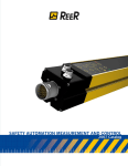
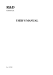
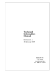
E-Caling(xiamen) Eelectronic Co.,LTD
EC-101 Intelligent Controller
User Manual V1.1
E-Caling(xiamen) Eelectronic Co.,LTD
1
E-Mail:[email protected] or [email protected]
E-Caling(xiamen) Eelectronic Co.,LTD
Content
Unit 1
Introduction·······························································································3
1.1 Brief introduction
1.2 Model introduction
1.3 Outline dimension and Install Hole size
1.4 Main specification
1.5 Terminal connection
Unit 2
Operation instruction ··············································································9
2.1 Panel introduction
2.2 States of the Instrument
2.3 Operation instruction
2.4 Parameters setting:
2.5 Parameters table:
2.5.1 For example introduction:
2.5.2 Alarm setting:
2.5.3 Cold-junction compensation:
Unit 3
Function Introduction·············································································14
3.1 Alarm
3.2 Transform output
3.3 Pillar-light simulated display
3.3 Example
Unit 4
Communication protocol·······································································16
4.1 Communication rules
4.2 Answer command format
4.3 Data format
4.4 Communication instruction
4.5 Parameter code table
2
E-Mail:[email protected] or [email protected]
E-Caling(xiamen) Eelectronic Co.,LTD
Unit 1
Introduction
1.1 Brief Instruction
EC-101 intelligent controller is an intelligent and high-precision measuring and control instrument to display
liquid level, temperature and pressure in digital. Equipped With level sensor, pressure sensor, temperature
sensor and transducer it can make all ranges of measuring and control system for level, temperature and
pressure.
The input of EC-101 intelligent controller may be T.C, RTD, 0-10mA or 4-20mA standard current and 0-5V
or 1-5V standard voltage, and it can be changed freely.
There are four alarm outputs and each can be defined as upper limit alarm or lower limit alarm. The output
can be standard current transform output of 0-10mA or 4-20mA and the sensor power supply output of
12VDC/50mA, 5VDC/50mA and 24VDC/50mA.
Features
◆Adopting the most advanced ATMEL single chip Microcomputer reduce the peripheral components and
improve its reliability;
◆integrate universal input, several output methods in one controller;
◆Adopt multi advanced techniques, such as WATCHDOG circuit, software trap & instruction redundancy,
power-off protection, digital filter and so on, field fault-tolerant ability is highly paid attention to; all these
techniques make the controller has strong anti-interference capability;
◆Adopting modularized output interface, the function configuration is convenient and flexible;
◆Double four-bit LED digital display, it can display measured value and the 1st alarm value;
◆With pillar-light of 20 segments display measured value;
1.2 Model introduction
EC-101
Outline
(mm)
introduction
dimension
Main output
Output 1(AL1)
Output 2(AL2)
A:96×96 B:48×96
C:96×48
D:160×80 E:80×160 F:72×72
G:48×48
N:None
J1:Relay output(3A normal open + normal close)
J2:Relay output (0.8A normal open)
J3 : two channels of Relay output (0.8A normal
open×2)
T:Solid state relay triggering output (12V/40mA)
N:None
J:Relay output(3A normal open)
T:Solid state relay triggering output (12V/40mA)
N:None
J:Relay output(3A normal open)
T:Solid state relay triggering output (12V/40mA)
V1:DC 12V/50mA sensor power supply
V2:DC 24V/50mA sensor power supply
V3:DC 5V/50mA sensor power supply
V5: Voltage transform output 0-5V
I:Current transform output (0-10mA 4-20mA)
3
E-Mail:[email protected] or [email protected]
E-Caling(xiamen) Eelectronic Co.,LTD
EC-101
introduction
N:None
V1:DC 12V/50mA sensor power supply
V2:DC 24V/50mA sensor power supply
V3:DC 5V/50mA sensor power supply
Voltage transform output 0-5V
I:Current transform output (0-10mA 4-20mA)
Output 3(AL3)
R: RS232 communication
S: RS485 communication
0:Thermocouple, RTD, 0-5V, 1-5V
1:Thermocouple, RTD, 0-10mA, 4-20mA
Input mode
Remark:Note in the table“□”means,For example:
EC-101A JJJV1,its means below
EC-101 A J J J V 1
A: means 96×96mm
J: means Relay main output
J: means Relay secondary output 1
J :means Relay secondary output 2
V: means Voltage secondary output 3
1: means Thermocouple 1 input
1.3 Outline dimension and Install Hole size :
Outline dimension code A
Outline dimension code B
Outline dimension code C
Panel size:
Panel size:
96(W)×96(H)×(D)105mm
96(W)×48(H)×(D)105mm
48(W)×96(H)×(D)105mm
Install Hole size :
92(W)×92(H),D>105mm
Install Hole size :
92(W)×45(H),D>105mm
Install Hole size :
45(W)×92(H),D>105mm
Install Hole size
Panel size
Panel size:
4
E-Mail:[email protected] or [email protected]
E-Caling(xiamen) Eelectronic Co.,LTD
Outline dimension code D
Outline dimension code E
Outline dimension code F
Panel size:
Panel size:
160(W)×80(H)×(D)105mm
80(W)×160(H)×(D)105mm
72(W)×72(H)×(D)105mm
Install Hole size :
152(W)×76(H),D>105mm
Install Hole size :
76(W)×152(H),D>105mm
Install Hole size :
68(W)×68(H),D>105mm
Install Hole size
Panel size
Panel size:
Outline dimension code G
Panel size:
Install Hole size
Panel size
48(W)×48(H)×(D)105mm
Install Hole size :
45(W)×45(H),D>105mm
1.4 Main specification
◆ Accuracy: ±0.2% F.S ±1digit
◆ Power supply: 85V-264V or DC24V
◆ Power consumption: < 4w
◆ Ambient temperature: -15-60℃
◆Ambient humidity: <85% RH
◆Input signal:(remark:Sensor error or over range: Sb)
5
E-Mail:[email protected] or [email protected]
E-Caling(xiamen) Eelectronic Co.,LTD
S.N.
Input model
1
Thermocouple
2
3
RTD
Standard
current
Standard
voltage
4
Measuring
range
Code
Input model
Measuring
range
0
1
2
3
8
Input
model
K
S
B
T
Pt100
0--1300℃
0--1700℃
0--1800℃
-200--400℃
-200--600℃
4
5
6
7
9
E
J
Wre325
N
Cu50
-200--1000℃
0--800℃
0--2300℃
0--1300℃
-50--150℃
14
DC 0-5V
-999-9999
15
DC 1-5V
-999-9999
16
4-20mA
-999-9999
17
0 - 10mA
-999-9999
Code
◆ Output Signal
S.N.
1
Output mode
Relay
on/off
output
Current
transform
output
Sensor power
supply
2
3
Output 1
AC220V/3A
Output 2
AC220V/1A
Output
/
3
0-19mA
4-20mA
/
DC24V/50mA
DC12V/50mA
DC5V/50mA
◆ Cold-junction compensation error: ±1 o C
◆ Resolution: 0.1℃
◆ Display mode: 2 x 4 bit LED digital display, pillar-light of 20 segments
◆The sampling period:0.5s
◆ Control mode: the four alarm can be set as upper limit alarm or lower limit alarm freely.
1.5 Terminal Connection (please refer to the connection diagram on meter shell):
1) 96 X 96, 48 X 96(V), 80 X 96(V):
Note:
a) The output of EC-101 includes four parts: main control output (OUT), ALiliary output1 (AL1), ALiliary output2
(AL2), ALiliary output3 (AL3). The terminal function has multi definitions and it is determined by the function
of the output interface mounted. The connection is based on black point symbol;
b) The input of terminals “11” & “12” is 0-5V or 1-5V when delivery if not indicated when ordered. If the exact
input is 0-10mA or 4-20mA, may parallel connect a 500ohm or 250ohm precision resistance to input
terminals;
c) c) If J3 is selected for main output, that is there are two channel’s alarm, terminal ’13’ & ‘14’ corresponds to
the 4th alarm, the indicator corresponds to AL3;
6
+
E-Mail:[email protected] or [email protected]
E-Caling(xiamen) Eelectronic Co.,LTD
2) 96 X 48(H), 160 X 80(H):
Note:
a) The output of EC-101 includes four parts: main control output (OUT), ALiliary output1 (AL1), ALiliary
output2 (AL2), ALiliary output3 (AL3). The terminal function has multi definitions and it is determined
by the function of the output interface mounted. The connection is based on black point symbol;
b) The input of terminals “11” & “12” is 0-5V or 1-5V when delivery if not indicated when ordered. If the
exact input is 0-10mA or 4-20mA, may parallel connect a 500ohm or 250ohm precision resistance to
input terminals;
c) If J3 is selected for main output, that is there are two channel’s alarm, terminal ’13’ & ‘14’ corresponds
to the 4th alarm, the indicator corresponds to AL3;
3)72 x 72 (H):
Note:
a) The output of the instruments includes three parts: main control output (OUT), ALiliary output1 (AL1),
ALiliary output2 (AL2). The terminal function has multi definitions and it is determined by the function
of the output interface mounted. The connection is based on black point symbol;
b) The input of terminals “10” & “11” is 0-5V or 1-5V when delivery if not indicated when ordered. If the
exact input is 0-10mA or 4-20mA, may parallel connect a 500ohm or 250ohm precision resistance to
input terminals;
4)48 x 48:
Note:
a) The output of the instruments includes two parts: main control output (OUT), ALiliary output1 (AL1).
The terminal function has multi definitions and it is determined by the function of the output interface
mounted. The connection is based on black point symbol;
b) The input of terminals “10” & “8” is 0-5V or 1-5V when delivery if not indicated when ordered. If the
exact input is 0-10mA or 4-20mA, may parallel connect a 500ohm or 250ohm precision resistance to
input terminals;
7
E-Mail:[email protected] or [email protected]
E-Caling(xiamen) Eelectronic Co.,LTD
c) There is no linear input option for the instruments when delivery, if the input signal is standard current
or voltage, please move the jumper to the other two holes in the main output module (please refer to
the diagram);
Diagram of G type main board:
8
E-Mail:[email protected] or [email protected]
E-Caling(xiamen) Eelectronic Co.,LTD
Unit 2 Operation instruction
2.1 Panel introduction
Take type A (96 × 96mm) as example:
⑴
(SET)button:
◆ Keep pressing more than 3 seconds to switch between normal display state and setting state;
◆ In setting state, press once to save the new set value of parameters and select the next parameter to
be set;
⑵
(A/M)button:A:means auto,M:means manual,and moves the cursor toward left
In setting state,used for moving the point toward the left.
⑶
UP button:
In setting state,used for increasing Numbers.
⑷
Down button:
In setting state,used for reducing Numbers.
⑸Upper display window(PV):
◆ In normal display state, it displays measured value。
◆ In setting state, it displays the symbol of parameter to be set
⑹Lower display window (SV):
◆In normal display state, it displays the 1st alarm value;
◆In setting state, it displays the set value of the selected parameter;
⑺ OUT:the first alarm indicator
9
E-Mail:[email protected] or [email protected]
E-Caling(xiamen) Eelectronic Co.,LTD
OUT indicator is on when it meets the condition of the first alarm and the first alarm output terminals 15 & 16
close at the same time; contrarily, out indicator is off and the first alarm output terminals open.
⑻
AL1:the second alarm indicator
indicator is on when it meets the condition of the second alarm and the second alarm output
terminals 3 & 4 close at the same time; contrarily, AUX1 indicator is off and the second alarm output
terminals open.
⑼ AL2:the third alarm indicator
indicator is on when it meets the condition of the third alarm and the third alarm output terminals 5 & 6
close at the same time; contrarily, AUX2 indicator is off and the third alarm output terminals open;
⑽ AL3:the fourth alarm indicator
indicator is on when it meets the condition of the fourth alarm and the fourth alarm output terminals 7 &
8 or 13 & 14 close at the same time; contrarily, AUX3 indicator is off and the fourth alarm output
terminals open.
1) ⑾
20 segments pillar-light
It is used to display the measured value in simulation and its corresponding measured value is
determined by LoL and HiL.
2.2 States of the Instrument
Normal state: When the instruments work in the normal state, upper window displays measured value and
lower window displays the first alarm value;
Setting state: When the instruments work in parameters setting state, upper window displays the
parameters to be set and lower window displays the set value of the parameters.
2.3 Operation instruction
Power on self test
1、Connect the instrument correctly according to the terminal connection diagram on shell: power (terminal
1 & 2), input, output and alarm;
2、Check the connection carefully and make sure it is correct, then turn power on;
3、The instrument enters self test state at once when power on. Upper window (PV) displays measured
value; lower window (SV) displays the first alarm value. If there is error, upper window (PV) displays
‘SYS’ and lower window (SV) displays ‘Err’.
2.4 Parameters setting:
Brief introduction of Parameter Setting
In the normal display state, keep pressing
for 3 seconds, the system will enter parameter setting
state.
In setting state, press
normal state.
once to amend the next parameter; keep pressing
for 3 seconds to enter
10
E-Mail:[email protected] or [email protected]
E-Caling(xiamen) Eelectronic Co.,LTD
2.5
Parameters table:
Symbol
Parameter definition
Setting range
Notes
Loc
ON: enable parameter change;
Parameter modification enable
ON/OFF
OFF: disable parameter change
HL1
The first alarm mode
ON/OFF
ON: upper limit alarm
OFF: lower limit alarm
HL2
The second alarm mode
ON/OFF
ON: upper limit alarm
OFF: lower limit alarm
HL3
The third alarm mode
ON/OFF
ON: upper limit alarm
OFF: lower limit alarm
HL4
The fourth alarm mode
ON/OFF
ON: upper limit alarm
OFF: lower limit alarm
cP
Cold junction compensation
Poin
Decimal point determined
ON/OFF
Cold-junction automatic/ no compensation
--.-/---
When -100<display value<1000, the decimal point is
at digit of tens’, or else at digit of ones.
--.--/-.---oSEt
Zeroing coefficient
LoL
Lower limit of analog display
-99.9-99.9
Display value=measured value + oSEt
Linear input 0mA,4mA,0V and 1V,
Lower limit of linear input
Display value corresponding to transform output of
-999-9999
HiL
Display value corresponding to
0mA or 4mA
lower limit of transform output
lower limit of analog display value
Upper limit of analog display
Linear input 10mA,20mA,5V and 10V,
Upper limit of linear input range
Display value corresponding to Transform output of
-999-9999
Hy
Display value corresponding to upper
10mA or 20mA
limit of transform output
upper limit of analog display value
Hystersis of alarm
0-25.5
non-sensitive area of alarm
Sn
0:K, 1:S, 2:B, 3:T, 4:E, 5:J, 6:Wre, 7:N, 8:Pt100,
Input type
0-17
9:Cu50, 10:Cu100, 14:0-5V, 16: 4-20mA,
17:0-10mA
FiL
Input filter coefficient
0-100
oP
No filter function when it is 0
0-10
0-10mA current output
Transform output mode
4-20
4-20mA current output
Remark:In the table set range for alarm value:-999-9999
11
E-Mail:[email protected] or [email protected]
E-Caling(xiamen) Eelectronic Co.,LTD
2.5.1 For example introduction:
Set parameter HiL to be 800,and the original set value is 600
①Keep pressing SET for 3
seconds, the system enters
④ Press A/M to move
the cursor to hundreds
②Unlock by pressing
UP or DOWN
⑤ Press UP to set the
hundreds digit to be 8
③Press SET several
times until the upper
⑥ After finishing the setting, keep pressing
SET for 3 seconds to exit from parameter
2.5.2 Alarm setting:
The instruments have four channels alarm; the alarm may be set to be upper limit and lower
limit alarm via setting alarm mode parameter (HL1, HL2, HL3 and HL4). Example: the alarm
output is upper limit alarm, user just need to set HL1, HL2, HL3 and HL4 to be ‘ON’;
Example: adopts the 1st alarm and set it to be upper limit alarm; when the temperature beyond
2000℃ the 1st alarm output terminals close;
① Keep pressing SET for 3 seconds, the
system enters parameter setting state;
② Unlock by pressing
UP or DOWN;
③ Press SET several times, until upper
window displays HL1; press UP button to
set it to be ‘ON’;
12
E-Mail:[email protected] or [email protected]
E-Caling(xiamen) Eelectronic Co.,LTD
④ Press SET to select
⑤ Press A/M to move the
⑤Press UP and DOWN to
parameter OUT1, the ones
point .
set OUT1 to be 2000.
⑥After finishing
the Setting, keep
2.5.3 Cold-junction compensation:
When the input is thermocouple, and cold-junction compensation is needed, parameter cP should be
‘ON’.
Linear input
If the input is standard current or voltage, such as the output of the transmitter of level, pressure and temperature, the
lower limit of linear input LoL and the upper limit of linear input HiL should be set according to the nominal value. For
example, the instrument is connected with level transmitter, the output of the transmitter is 4-20mA and the
corresponding pressure is 0m-10m, the parameter should be set as follow:
Poin= - - -. –
Or
Poin= - -. –
Sn=16
Sn=16
LoL=0.0
LoL=0.00
HiL=10.0
HiL=10.00
Input Type
For set range of input type parameter Sn, please refer to parameter table;
Example: if the input is 4-20mA, then Sn should be 16;
Input Type
For set range of input type parameter Sn, please refer to parameter table;
Example: if the input is 4-20mA, then Sn should be 16;
2.5.4 Transform output
The transform output of the instruments can be set to be 0-10mA or 4-20mA freely.
The transform range is determined by parameter LoL and HiL, Example:
The measured value is for temperature, set:
LoL=0
HiL=100
oP=4-20
When measured value is more than or equal to 100℃, the transform output is 20mA;
13
E-Mail:[email protected] or [email protected]
E-Caling(xiamen) Eelectronic Co.,LTD
When measured value is 50℃, the transform output is 12mA.
Note: As to linear current input (0-10mA, 4-20mA) and linear voltage input (0-5V, 1-5V), only one kind can
be chosen when ordering. Without specification, the linear voltage input (0-5V, 1-5V) is adopted; if the field
input is current, please parallel connect a precision resistor between the input terminals: if the field input is
0-10mA, please parallel connect a resistor of 500ohm, and set Sn to be 14; if the field input is 4-20mA,
please parallel connect a resistor of 250ohm, and set Sn to be 15.
Unit 3
Function introduction
3.1 Alarm
a) When measured value is less than lower limit, the indicator is on and alarm contact close;
b) When measured value is bigger than upper limit, the indicator is on and alarm contact close;
c) Alarm hytersis (Hy)
Upper limit alarm
Lower limit alarm
OUT+Hy
OUT+Hy
OUT
OUT
OUT-Hy
OUT-Hy
OFF
ON
OFF
OFF
Figure 1
ON
OFF
Figure 2
In order to avoid the frequent action of alarm output when the measured value is fluctuating at the critical
point of alarm, the parameter of alarm hytersis Hy is used.
When measured value increases to OUT1+Hy, upper limit alarm exports; when measured value
decreases to OUT1, the alarm does not stop; only when measured value is less than OUT1-Hy, the alarm
stops; refer to Figure 1.
When measured value decreases to OUT1-Hy, lower limit alarm exports; when measured value increases
to OUT1+Hy, lower limit alarm stops; refer to Figure 2.
3.2 Transform Output
The measured value can be converted to 0-10mA or 4-20mA standard current. The current output form is
determined by parameter oP and the transform range of measured value is determined by the parameters
LoL and HiL.
1)
When the input is linear, the transform output is the conversion output of the input signal. For example,
assume the input is 0-10mA (Sn=17) and transform output is 4-20mA (oP=4-20), when the input is
14
E-Mail:[email protected] or [email protected]
E-Caling(xiamen) Eelectronic Co.,LTD
0mA, the output is 4mA; when the input is 10mA, the output is 20mA.
When the input is thermocouple or RTD, the transform output range is determined by LoL and HiL.
2)
For example, if LoL=200, HiL=800 and oP=4-20, when the measured value is 200 o C , the output is
4mA; when the measured value is 800 o C , the output is 20mA.
3.3 Pillar-light simulated display
There are 20 segments pillar-light to display measured value, the display range is determined by LoL and
HiL:
When measured value is less than or equal to LoL set value, the pillar-light are all off;
When LoL set value<measured value<HiL set value, the segments of alighted pillar-light is proportional to
the measured value;
When measured value is bigger than or equal to HiL set value, t the pillar-light are all on.
3.4 Example
3.4.1 The instrument is used to control liquid level, and when the level is higher than 9m, upper limit alarm
exports; when the level is lower than 2m, lower limit alarm export. The liquid level transmitter is of
2-wire 4-20mA output and the corresponding value is 0-10m; the parameters are set as follows:
HL1=oN,
LoL=0.0
HL2=oFF,
HiL=10.0
Poin=---.-,
Hy=0.2
OUT1=9.0,
Sn=16
OUT2=2.0
3.4.2 Connection Example
85-265VAC
Alarm 2
_
DC24V
2-wire
Transmitter
+
4-20mA
1
9
2
10
3
11
4
12
5
13
6
14
7
15
16
8
_
+
Alarm 1
Sn=16
LoL=**** (lower limit of transmitter measuring range)
LiL=**** (upper limit of transmitter measuring range)
15
E-Mail:[email protected] or [email protected]
E-Caling(xiamen) Eelectronic Co.,LTD
85-265VAC
Alarm 2
_
Remote
DC5V
Pressure
+
Transducer
1
9
2
10
3
11
4
12
5
13
6
14
7
15
16
8
_
+
Alarm 1
Sn=14
LoL=**** (lower limit of transducer measuring range)
LiL=**** (upper limit of transducer measuring range)
Unit 4
Communication protocol
4.1 Communication rules
LU-904M adopts asynchronous serial communication, can be equipped with RS-232C, RS422A or RS485
communication interface, and may communicate with baud rate of 1200-9600. Format of serial data frame
is 1 start bit (bit 0), 8 data bit (bit 1-8), 1 addressing bit (bit 9) and 1 stop bit, total 11 bits; the data is hex.
4.2 Answer command format
In each communication instruction, the instrument returns following message at the end:
or
4FH
4BH (OK)
means communication success
3FH
3FH (??)
means communication fail
4.3 Data format
1)
Data format: complement of two bytes.
2) Parameters with specified range.
a) MV: range of current transform output, range: 0 – 200; MV=0 means current transform output is 0mA, and
MV=200 means current transform output is 20mA;
b) Status flag: range: 0 - FFH. 8 bits of it respectively represent 8 parameters of on/off; below pleas see the
details.
7
HL4
6
5
4
3
cP
HL3
2
1
0
HL2
HL1
Loc
16
E-Mail:[email protected] or [email protected]
E-Caling(xiamen) Eelectronic Co.,LTD
‘1’ means ON,
‘0’ means OFF.
c) oP: transform output mode; oP=2 means 0-10mA transform output; oP=3 means 4-20mA transform output;
d) bAud: baud rate, range: 0-3, which means 1200, 2400, 4800 and 9600 respectively;
Hy, Sn, FiL, oP, Addr, bAud and status flag are all parameters of single byte, so they should be filled with ‘0’ in
high byte when written.
4.4 Communication instruction
4.4.1 Addressing instruction
When the host computer wants to communicate with some instrument, it should send an addressing
instruction first. The addressing instruction is single byte instruction, bit 1-8 is address and bit 9 is ‘1’
(Non-addressing instruction is ‘0’ ). The address of the instrument is determined by parameter Addr. The
instrument make a cooperation of the address in the addressing instruction and the address of its own, if
they are same, the instrument will start to communicate with the host computer. To the instrument in
communication, if it receives an addressing instruction in which the address is not the address of its own, it
will close the function of communication.
For example, if the Addr of the instrument is 3, when it is addressed, the format is as follows:
0
1
1
0
0
0
0
0
0
1
0
1
2
3
4
5
6
7
8
9
4.4.2 Survey read (E)
Instruction format: 45H
Return value: PV, SV, MV, 4FH 4BH (OK)
The low byte is at front and the high byte is behind, here SV is no meaning;
4.4.3 Read (R)
Instruction format: 52H + parameter code
Return value: parameter value + 4FH 4BH
4.4.4 Write (W)
Instruction format: 57H + parameter code + parameter value
Return value: 4FH 4BH
4.4.5 End instruction (O)
Instruction format: 4FH or addressing instruction which is not for local machine (bit 9 is ‘1’);
None return value.
17
E-Mail:[email protected] or [email protected]
E-Caling(xiamen) Eelectronic Co.,LTD
4.5 Parameter code table
Code
Parameter
Code
Parameter
Code
Parameter
Code
Parameter
0
MV
6
OUT2
12
HiL
18
----
1
----
7
OUT3
13
Hy
19
----
2
Status Flag
8
OUT4
14
----
20
oP
3
----
9
oSEt
15
Sn
21
Addr
5
OUT1
11
LoL
16
FiL
22
bAud
The distributed control system is characterized of centralized administration and distributed control, which is
composed of Anthone intelligent instrument and superior computer. Control and data collection are done by
inferior instrument. The superior computer performs real-time supervisory control of whole process, records
and prints the history data. The fault of the superior computer does not affect the inferior instrument and
there is no fault diffusion between inferior instruments for the distributed control. Therefore, it reduces the
probability of system crash caused by local faults. Now the price of PC is very cheap and there is almost no
limit of memory capacity, so it has good cost performance.
Anthone DCS adopts RS485 communication rules when there are multi-set of instruments communicating
and the max. Communication distance is 1km. One communication line is allowed to connect with 128 sets
of Anthone serial intelligent instruments at most, and the system structure is very simple and convenient.
For more information, please contact with the suppliers.
18
E-Mail:[email protected] or [email protected]