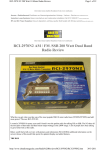
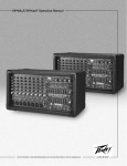
1
IREEF1
(Communications, Inc.
IR7
1FRINMaM
VNiTh1(4!I ITITI1k!L41
Communcations,
with Built-in Frequency Counter
867 Bowsprit Road
Chula Vista, CA 91914
EmaiI:sa1es@rangerusacom
http: //wwwsangerusacom
.....................................7.
............... . . . ........ ........................................... .. .... ..............
:1
L
PRINTED IN TAIWAN
PIN:A38251 616A
t?85E150
.........
d o
L
......................
'
Ranger
LIO
.......
C
I
J
User's Manual
Chapter 1 Specifications
Table of Contents
..... .
PAGE
Chapter 1 Specifications
2
Chapter 2 Installation
3
Installing the Radio.................................................................
3
Ignition Noise Interference..........................................................
4
GENERAL
Model
Mode",
RC69FF04
Frequency Range :
1. 28,245 - 28.685 MHz
2.28.695 - 29,135 MHz
3, 29.145 - 29.585 MHz
4.28.315 - 28.755 MHz
5. 28.765 - 29205 MHz
6. 29.215 - 29.655 MHz
Antenna................................................................................
4
External Speaker........................................................................
...........................................
4
4
Public Address..................................
Chapter 3 Operation ...............................................................
5
Controls and Indicators..................................................................................................................
5
..........................................................................
FrontPanel..
5
Rear Panel. .........................................................................................................8
................................................................................
........
9
Operation....................................................................... .............................................
...........
Microphone
9
Procedure to Receive............................................................................. 10
Procedure to Transmit................................................................................ I 0
Memo...................................................................................... 11
LIMITED WARRANTY........... .... ............................... ..Inside Back Cover
Modes
CW/FM!AM!SS8
Frequency Control
Phase-Lock-Loop Synthesizer
Frequency Stability
0001%
Temperature Range -300C to +50°C
Input Voltage
DCI3.8V
Antenna Impedance 50 ohms
7 7/8 (\f 1 x I I 1/8! (D) x 3 114 (H)
Size
)
Weight
Bib 3oz.
TRANSMITTER
AM/FMICW: 200W, RMS
SSB: 400W. PEP
Spurious Emissions 50 dB
RfPower Output
Audio Distortion
10%
Frequency Response 300 to 2500Hz
Microphone
NOTE
Amateur Radio License is required to operate this device. For licensing
information within the United States of America, visit http//wwwfccgov,
for residence of Canada, visit http:llwww.racca
Dynamic
RECEIVER
Sensitivity
Squelch Sensitivity
Selectivity
614V/AM: 0.5 pVfor 10dB S+N/N
FM: 025pV for 12dB S±N/N
SSB: 015pV forlOdB S+N/N
0.5 pV
55 dB
Image Rejection
-50 dB
Hum & Noise----------
40dB
Audio Power Output 2.5W at 10% THD
(SPECFlCATtDNS SUBJECT TO CHANGE WITHOUT NOTICE)
----------- ------
Chapter 2 Installation
Installation
- -------------------- (Continued)
Installing the Radio
4, Mount the microphone bracket near the radio in an easily accessible
spot using the two screws provided.
Choose a convenient location for operation that does not interfere with
driver or passenger. This radio is supplied with a universal mounting
bracket. When mounting the bracket and radio to your car, make sure it is
mechanically strong. Also, provide a good electrical grounding
connection to the chassis of the vehicle. Proceed as follows to install the
radio.
1. Locate a convenient area in your vehicle for the installation of the
radio. Hold the mounting bracket with the radio in the location where the
radio is to be installed. Make sure nothing will interfere with either the
radio or the mounting bolts. Mark and then drill holes for the mounting
bracket.
2. Most radio antennas come equipped with a PL-259 plug. Connect
this plug to the ANT. Jack in the rear of the radio.
3. Extending from the rear of the radio is a fused red and black wire for
the DC connections to the vehicles electrical system. For best
performance, it is strongly recommended that the red lead be taken
directly to the positive terminal on the vehicles battery and the black lead
be connected to the nearest chassis ground. (Note: This radio is
designed for vehicles with negative ground systems.)
Connections should be made using appropriate "crimp on" lugs of a
size large enough to make good contact with the bolt used to fasten to
the battery and the chassis ground, It is a good safety idea to install a
second fuse, in series with the red wire at the battery connection. This
second fuse would provide protection in case the red wire was to 'fray"
or get pinched and short to the body of the vehicle, some where between
the battery and the radio.
High power radios such as this one require large DC current flow when
in the TX mode. Poor power connections can cause supply voltage drops
that can substantially decrease the performance of your radio. A good DC
connection is probably one of the most important things for getting the
best transmitter performance and in some cases, least receiver noise.
--
_
Ignition Noise Interference
With weak signals, you may experience interference of the signal by
background noise. This radio has NB and ANL controls which will help
reduce background noise from sources such as your ignition system.
However, background electrical noise may come from several sources
and all noise may not be eliminated. With extremely weak signals, you
can operate this radio with the engine turned off, which should improve
reception. If the ignition noise level is too high to allow proper operation
under most conditions, you should have your installation of the radio
checked by a qualified technician.
Antenna
This radio has a jack in the rear for a standard PL-259 antenna plug. If
you are looking for the most range for your transmission, use a vertically
polarized, quarter-wave length antenna. If antenna height is a problem,
you may use a shorter, loaded-type whip antenna although you can
expect some lost of transmission range.
To improve performance, your antenna shoud be matched to your radio.
Your antenna can be adjusted so that it matches your radio.
External Speaker
The external speaker jack (EXT. SPK) on the rear panel is used for remote
receiver monitoring. The external speaker should have 8 ohms impedance
and be able to handle at least 4watts. When the external speaker is
plugged in, the internal speaker is disconnected.
Public Address
To use the Public Address (PA) function, first connect an external speaker
to the PA. SP. Jack on the rear of the radio. See the above specifications
for a proper external speaker. Keep the speaker away from the
microphone to avoid acoustic feedback.
Operation (ContinueI
Chapter 3 Operation
Controls and Indicators
4, MIC GAIN CONTROL: Adjust the microphone gain in the transmit
mode. This control is used to set the audio level of the microphone
-6.
(
1i
ci:
1
9
for maximum performance and clarity.
",.........
5* RF POWER CONTROL: This control enables adjustment of RF power
output continuously up to the rated output power.
t
................. ......
(
)
.
.
Ir
,
. .
jn,
'I
L I
c,i
..4....................
•
6 TALKBACK/OFF CONTROL: Adjust this knob for desired volume of
Talkback. This is used to monitor your own voice. Or example, you
could use this feature to compare different microphones.
1 in
1
r
f
.
c
,
7. Fr. POOL: The Frequency Pool allows the user to select the desired
segments of frequencies
0
8. MODE SWITCH: This switch allows you to select one of following
operating modes: CW/FMiAMi'LSB/US8
_J4
) ))
Front Panel
1. SQUELCH CONTROL: This control is used to control or eliminate
receiver background noise in the absence of an incoming signal. For
maximum receiver sensitivity, it is necessary that the control be
adjusted only to the point where the receiver background noise is
eliminated. Turn fully counterclockwise and then slowly clockwise
until the receiver noise just disappears. Any signal to be received
must now be slightly stronger than the average received noise.
Further clockwise rotation will increase the threshold level that a
signal must overcome in order to be heard, Only strong signals will
be heard at a maximum clockwise squelch setting.
2. ON/OFF VOLUME CONTROL: Turn clockwise to apply power to the
radio and to set the desired listening level.
a RF GAIN CONTROL: This control is used to reduce the gain of the RF
amplifier under strong signal conditions
9. COARSE/FINE CONTROL: Allows variation of the receiver operating
frequency above and below the assigned frequency. Although this
control is intended primarily to tune in SSB signal, it may be used to
optimize AM/FM signals as described in the operating procedure
Oaragraphs. (Coarse and Fine operates both TX/RX).
10 FREQUENCY SELECTOR: This control is used to select a desired
transmit and receive frequency.
11. FRONT PANEL METER: The front panel meter allows the user to
monitor signal strength and RF power out level.
12 TXIRX LED: The red LED indicates the radio is in the transmit mode.
The blue indicates the radio is in the receive mode.
13 FREQUENCY COUNTER: This frequency counter indicates the
transmit frequency digitally.
14. ECHO SWITCH: This control is used for echo effect.
Operation ( Contin1DJii ...... .
......
-
15 Hi/LOW TONE SWITCH: This switch changes tone quality in receive
only. In LO position, bass is increased and in HI position, treble is
increased,
Operation (Continued)
Rear Panel
16 SRF/SWR SWITCH: In the S-RF position, the meter swings
proportionally to the strength of the received signal. When
transmitting, the meter indicates relative RF output power, When in
the SWR position, the Standing Wave Ratio (SWR) of your antenna.
There are no adjustment because the SWR circuit in this radio
calibrates itself automatically.
17 NB/ANL SWITCH: In the NB/ANL position, the RF Noise Blanker and
the automatic Noise Limiter in the audio circuits are also activated
The Noise Blanker is very effective in eliminating repetitive impulse
noise such as ignition interference.
18. ROGER BEEP SWITCH: When this switch is placed in the ROGER
BEEP position, the radio automatically transmits an audio tone at the
end of your transmission. This indicates the end of your transmission
so that people who are having trouble hearing you will know that you
are done speaking. As a courtesy to others, use the Roger Beep only
when necessary.
19. +10KHz SWITCH: In the +10KHz position, the transmit and receive
frequency is shifted 10KHz up.
20. CHANNEL DISPLAY: The channel display indicates the current
selected channel.
-7-
2. POWER: This accepts 13.8 VDC power cable with built-in fuse. The
power cord provided with the radio has a black and red wire. The
black goes to negative and the red goes to positive
3, CW KEY: The CW key is used for Morse Code operation. To operate
this mode, connect a CW key to this jack, and place the MODE switch
in the OW position.
4, EXTERNAL SPEAKER: This jack accepts a 4 8 ohm, 5watt external
speaker. When the external speaker is connected to this jack, the
built-in speaker will be disabled.
uperation (Continued)
LI.
.
Operation (Continued)
"IN
- - — ----------
Operation
B. Procedure to Receive
A. Microphone
The receiver and transmitter are controlled by the push-to-talk switch on
the microphone. Press the switch and the transmitter is activated, release
switch to receive When transmitting hold the microphone two inches
from the mouth and speak clearly in a normal "voice" The transceiver
comes complete with low-impedance dynamic microphone
For best results, the user should select a low-impedance dynamic type
microphone or a transistorized microphone.
The microphone should provide the functions shown in schematic below.
Dhi Ah,mht-
I Be sure that power source, microphone and antenna are connected to
the proper connectors before going to the next step
2. Turn unit on by turning VOL knob clockwise
a Set the VOL for a comfortable listening level.
4. Set MODE switch to the desired operation mode.
5, Listen to the background noise from the speaker. Turn the SO knob
slowly clockwise until the noise just disappears. The SQ is now
properly adjusted. The receiver will remain quit until a signal is
actually received. Do not advance the control too far, or some of
weaker signals will not be heard.
M;,% (shk Iid
sniea
Audio Lead
Transmit Control
Receive Control
1LuaI0
I
2
3
4
6. Set the CHANNEL switch to the desired channel.
7. Set the RF gain control fully clockwise for maximum RF gain.
C. Procedure to Transmit
1. Select the desired channel of transmission.
2. Set the MIC GAIN to the level that will best suit your individual use.
3. If the channel is clear, press the push-to-talk switch on the
microphone and speak in a normal voice.
Transceiver Microphone Schematic Diagram
-9-
Ranger Communications Limited Warranty
Ranger Comniunic.aton, Inc. (Ranger) warrants to the ogna1 purchaser only this
product against defects in material or workmanship. as noted below,
hli'eeiive December I 2()01 the following Ranger Communications, mrs products
ore covered by n two (2) year limited warranty:
L Am thur Radio Products. RU 2950DX RC.l 2910 DX RU 29SCWX RCI
2'ThSl)X, RC12990DX, RCI-2995DX, RCI63001`111P. RCI6300FTB. RCI
69()OlHP RCI 69OO!TB R(l 6 )0F25 RU 6 001 150 RU ÔQO()F25 RCI
63001 150 RA 5054DX R(1 5054D\ 100 RU (3 C I
C1 631 1 ( 2 RC I
63FFC4, RCJ-69FFCI, RCII69FFC2, RCi69FFC4, RC1-2970N2.
2. Citizens Band Products: TRiOO Series, TR-296 (all models), TR396F, TIR.696F,
TR-696F SSB, TR-900 Series (all models).
The above products are warranted for the specified time period from the original date
of purchase as shown on the original purchasers bill of sale, receipted invoice, or
other proof of purchase. After this period, the original purchaser must pay for any
labor at the prevailing rate either at an authorized Ranger warranty repair facibty or at
the fttctory.
In the event of defect during the warranty period, Ranger shall, at its option, repair or
replace the defective product. Such action shall constitute the purchaser's exclusive
remedy under this warranty.
A Return Authorization Nwnher must be obtained from the Ranger Customer Service
Department before any returns fbr warranty repair will be accepted. Contact Ranger
Communications for Return Authorization at:
Ranger Communicaions, Inc.
867 Bowsprit Road
Chula Vista, CA 9191.4
Email: salcs(brangerusacom
This warranty does not cover cosmetic damage or damage due to acts ofOod, accident,
misuse, abuse, negligence, improper installation, lJNAUl1iORIZh'i) MODIFICATION,
or any action in violation of the product's instruction manual. This warranty is valid
only in the U. S A.
1. 'Limited" means that we will repair problems that are caused by factory defects,
only for the above mentioned products and time limit, at no charge. Work performed
by qualified technicians which did not cause any damage to the radio wilt not void the
warranty, Problems or damage caused by unqualified or misinfomied technicians,
operator abuse or other miscellaneous actions may he able to be repaired, but there will
be a charge. This warranty is muted to the radio only.
2. Generally, if the warranty sticker is removed or cut:, the radio is considered to he
"Void of Warranty". Ilowever, our policy is to he as lenient as we can, and to take this
into consideranon.. We will usually repair the radio - under warranty if no abuse or
misuse is found, Radios that have parts removed cut or clipped; or the l'CH has been
damaged., will not be repaired under warranty.
-14-