1
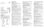
"Smarter Timing Solutions"
AFL3430
Antenna Fiber Optic Link
User Manual
AFL3430
Fiber Optic Link User Manual
Preface
Thank you for purchasing the AFL3430 Fiber Optic Link. Your new AFL3430 is fabricated using
the highest quality materials and manufacturing processes available today, and will give you years of
troublefree service.
About EndRun Technologies
EndRun Technologies is dedicated to the development and refinement of the technologies required to
fulfill the demanding needs of the time and frequency community.
Our innovative engineering staff, with decades of experience in the research and development of
receiver technology for the Global Positioning System (GPS), has created the most precise, stable,
and reliable GPS-derived time and frequency equipment in the world. These instruments have been
selected as the timing reference for such rigorous applications as computer synchronization, research
institutions, aerospace, network quality-of-service monitoring, satellite earth stations, and calibration
laboratories.
EndRun Technologies is committed to fulfilling your precision timing needs by providing the most
advanced, reliable and cost-effective time and frequency equipment available in the market today.
Part No. USM3430-0000-000 Revision 9
December 2013
Copyright © EndRun Technologies 2006-2013
AFL3430 User Manual
About This Manual
This manual will guide you through simple installation and set up procedures.
Introduction – The AFL3430, where to use it and its main features.
Basic Installation – How to connect, configure and troubleshoot your AFL3430.
Specifications – A detailed listing of all the pertinent specifications.
If you detect any inaccuracies or omissions, please inform us. EndRun Technologies cannot be held
responsible for any technical or typographical errors and reserves the right to make changes to the
product and manuals without prior notice.
Warranty
This product, manufactured by EndRun Technologies, is warranted against defects in material and
workmanship for a period of one year from date of shipment, under normal use and service. During
the warranty period, EndRun Technologies will repair or replace products which prove to be defective.
For warranty service or repair, this product must be returned to EndRun Technologies. Buyer shall
prepay shipping charges to send product to EndRun Technologies and EndRun Technologies shall
pay shipping charges to return product to Buyer. However, if returned product proves to be operating
normally (not defective) then Buyer shall pay for all shipping charges. If Buyer is located outside the
U.S.A. then Buyer shall pay all duties and taxes, if any.
Products not manufactured by EndRun Technologies but included as an integral part of a system (e.g.
peripherals, options) are warranted for ninety days, or longer as provided by the original equipment
manufacturer, from date of shipment.
Limitation of Warranty
The foregoing express warranty shall not apply to defects resulting from improper or inadequate
maintenance by Buyer or User, Buyer-supplied software or interfacing, unauthorized modification or
misuse, operation outside of the environmental specifications for the product, or improper site preparation or maintenance.
TO THE EXTENT PERMITTED BY LAW, THIS WARRANTY AND REMEMDIES SET FORTH
ABOVE ARE EXCLUSIVE AND IN LIEU OF ALL OTHER WARRANTIES, REMEDIES AND
CONDITIONS WHETHER ORAL OR WRITTEN, STATUTORY, EXPRESS, OR IMPLIED. AS
PERMITTED BY APPLICABLE LAW, ENDRUN SPECIFICALLY DISCLAIMS THE IMPLIED
WARRANTIES OF MERCHANTABILITY OR FITNESS FOR A PARTICULAR PURPOSE.
AFL3430 User Manual
Warranty Repair
If you believe your equipment is in need of repair, call EndRun Technologies and ask for a customer
service agent. It is important to contact us first as many problems may be resolved with a phone call.
Please have the serial number of the unit and the nature of the problem available before you call. If
it is determined that your equipment will require service, we will issue an RMA number. You will be
asked for contact information, including your name, address, phone number and e-mail address.
Ship the unit prepaid in the original container or a container of sufficient strength and protection to
EndRun Technologies. EndRun will not be responsible for damage incurred during shipping to us.
Be sure the RMA number is clearly identified on the shipping container. Our policy is to fix or repair
the unit within 5 business days. If it is necessary to order parts or if other circumstances arise that
require more than 5 days, an EndRun service technician will contact you.
Loaner units are not included as part of the standard warranty.
Repair After Warranty Expiration
If the warranty period has expired, we offer repair services for equipment you have purchased from
EndRun. Call and ask for a customer service agent. It is important to contact us first as many problems may be resolved with a phone call. Please have the serial number of the unit and the nature
of the problem available before you call. If it is determined that the equipment has failed and you
want EndRun to perform the repairs, we will issue you an RMA number. Ship the unit prepaid in
the original container or a container of sufficient strength and protection to EndRun Technologies.
EndRun will not be responsible for damage incurred during shipping to us. Customer is responsible
for shipping costs to and from EndRun Technologies. Be sure the RMA number is clearly identified
on the shipping container. After the equipment has been received we will evaluate the problem and
contact you with the cost to repair (parts and labor) and an estimate of the time necessary to complete
the work.
Limitation of Liability
The remedies provided herein are Buyer’s sole and exclusive remedies. EndRun Technologies shall
not be liable for any direct, indirect, special, incidental or consequential damages, whether based on
contract, tort or any other legal theory.
EndRun Contact Information
Address:
Phone:
Fax:
Sales:
Support:
EndRun Technologies
2270 Northpoint Parkway
Santa Rosa, California 95407
U.S.A.
(707) 573-8633
(707) 573-8619
1-877-749-3878 or (707)573-8633
[email protected]
1-877-749-3878 or (707)573-8633
[email protected]
AFL3430 User Manual
AFL3430 User Manual
Table of Contents
Preface . . . . . . . . . . . . . . . . . . . . . . . . . . . . . . . . . . . . . . . . . . . . . . . . . . . . . . . . . . . . . . . . . . i
About EndRun Technologies . . . . . . . . . . . . . . . . . . . . . . . . . . . . . . . . . . . . . . . . . . . . . . . . . . . . i
About This Manual . . . . . . . . . . . . . . . . . . . . . . . . . . . . . . . . . . . . . . . . . . . . . . . . . . . . . . . . . ii
Warranty . . . . . . . . . . . . . . . . . . . . . . . . . . . . . . . . . . . . . . . . . . . . . . . . . . . . . . . . . . . . . . . . ii
Limitation of Warranty . . . . . . . . . . . . . . . . . . . . . . . . . . . . . . . . . . . . . . . . . . . . . . . . . . . . . . ii
Warranty Repair . . . . . . . . . . . . . . . . . . . . . . . . . . . . . . . . . . . . . . . . . . . . . . . . . . . . . . . . . . iii
Repair After Warranty Expiration . . . . . . . . . . . . . . . . . . . . . . . . . . . . . . . . . . . . . . . . . . . . . . . iii
Limitation of Liability . . . . . . . . . . . . . . . . . . . . . . . . . . . . . . . . . . . . . . . . . . . . . . . . . . . . . . . iii
EndRun Contact Information . . . . . . . . . . . . . . . . . . . . . . . . . . . . . . . . . . . . . . . . . . . . . . . . . . iii
Main Features . . . . . . . . . . . . . . . . . . . . . . . . . . . . . . . . . . . . . . . . . . . . . . . . . . . . . . . . . . . . 1
Chapter One - Introduction . . . . . . . . . . . . . . . . . . . . . . . . . . . . . . . . . . . . . . . . . . . . . . . 1
Checking and Identifying the Hardware . . . . . . . . . . . . . . . . . . . . . . . . . . . . . . . . . . . . . . . . . . . 3
Chapter Two - Basic Installation . . . . . . . . . . . . . . . . . . . . . . . . . . . . . . . . . . . . . . . . . . . 3
NEMA Transmitter Physical Description . . . . . . . . . . . . . . . . . . . . . . . . . . . . . . . . . . . . . . . . . . . 4
Rackmount Transmitter Physical Description . . . . . . . . . . . . . . . . . . . . . . . . . . . . . . . . . . . . . . . . 5
Receiver Physical Description . . . . . . . . . . . . . . . . . . . . . . . . . . . . . . . . . . . . . . . . . . . . . . . . . . 6
Installing the AFL3430 Fiber Optic Link . . . . . . . . . . . . . . . . . . . . . . . . . . . . . . . . . . . . . . . . . . . 7
Mount the Fiber Optic Receiver . . . . . . . . . . . . . . . . . . . . . . . . . . . . . . . . . . . . . . . . . . . . . . . . . . 8
Install the Fiber Optic Transmitter (1U Rackmount) and GPS Antenna . . . . . . . . . . . . . . . . . . . . . . . . . . . . 8
Install Fiber Optic Cable . . . . . . . . . . . . . . . . . . . . . . . . . . . . . . . . . . . . . . . . . . . . . . . . . . . . . . 9
Power up Fiber Optic Link . . . . . . . . . . . . . . . . . . . . . . . . . . . . . . . . . . . . . . . . . . . . . . . . . . . . . 9
Troubleshooting the Fiber Optic Link after Initial Power Up . . . . . . . . . . . . . . . . . . . . . . . . . . . . . . . . . 10
Install the Fiber Optic Transmitter (NEMA Stainless Steel) and GPS Antenna . . . . . . . . . . . . . . . . . . . . . . . . 10
Install Fiber Optic Cable . . . . . . . . . . . . . . . . . . . . . . . . . . . . . . . . . . . . . . . . . . . . . . . . . . . . . 12
Power up Fiber Optic Link . . . . . . . . . . . . . . . . . . . . . . . . . . . . . . . . . . . . . . . . . . . . . . . . . . . . 12
Troubleshooting the Fiber Optic Link after Initial Power Up . . . . . . . . . . . . . . . . . . . . . . . . . . . . . . . . . 13
NEMA Fiber Optic Transmitter Cable Installation Details . . . . . . . . . . . . . . . . . . . . . . . . . . . . . . . 14
Appendix A - Specifications . . . . . . . . . . . . . . . . . . . . . . . . . . . . . . . . . . . . . . . . . . . . . . 15
AFL3430 User Manual
AFL3430 User Manual
"Smarter Timing Solutions"
ChapterOne
Introduction
The AFL3430 Antenna Fiber Optic Link provides a secure, low-loss means of connecting a standard
EndRun Technologies GPS antenna to GPS-based time and frequency products. It can be used in
applications where electrical isolation is required, for example when the antenna connection must
traverse a data security boundary, and where the antenna location necessitates an extremely long
cable run.
Main Features
The fiber optic link is a high-performance broadband downlink consisting of a fiber optic transmitter
in a stainless steel enclosure (or 1U rackmount enclosure), an interconnecting single-mode fiber optic
cable and a fiber optic receiver in a 1U rackmount enclosure. The fiber optic transmitter has a GPS
antenna input and is powered by an internal universal AC power supply. The fiber optic receiver, also
universal AC powered, has an RF output that provides the recovered GPS signal to the antenna input
of the attached timing equipment. The stainless steel fiber optic transmitter enclosure is suitable for
a dry industrial environment as supplied. It is suitable for wet and weather-exposed locations when
installed with liquid-tight conduit fittings.
1
AFL3430 User Manual
CHAPTER ONE
2
AFL3430 User Manual
"Smarter Timing Solutions"
ChapterTwo
Basic Installation
This chapter will guide you through the most basic checkout and physical installation of your
AFL3430 Antenna Fiber Optic Link.
Checking and Identifying
the Hardware
Unpack and check all the items using the shipment packing list. (Note that the AFL3430 Antenna Fiber Link receiver and transmitter may be shipped in separate boxes.) Contact the factory if anything
is missing or damaged. The AFL3430 shipment typically contains:
AFL3430 Fiber Optic Transmitter in one of the following configurations:
Stainless steel enclosure (part# 3430-0004-000), or
1U rackmount enclosure (part# 3430-0005-000)
AFL3430 Fiber Optic Receiver in 1U rackmount enclosure (part# 3430-0003-000)
AFL3430 User Manual (part# USM3430-0000-000)
Transmitter power cord, US, 1 per transmitter
AFL3430 Fiber Optic Receiver Cable Kit (part# 0648-0004-001), one per receiver:
Receiver power cord, US.
Fiber Optic Cable Warning Tag (attach per installation instructions).
Fiber Optic Starter Kit (part# 0608-0005-000), one per shipment:
Fiber Optic Cable, single-mode 8/125 um, FC/APC, 1 m (optional interconnect)
Receiver RF Interconnect TNC/TNC cable, 3 ft., one per shipment (optional interconnect)
3
AFL3430 User Manual
CHAPTER TWO
��������������
������� ����� ���������
�� ����� �����
����� ����� ����� �����
�������
����� ����� ���� �����������
��������� ����� ���������
���� ����� �� ��������
����� �� ����� �������
���� �� � �� �� �������
����� �������� �� ����
�������
�� ���� ���������� ���������� �������
�� ����� �������� ������ �� ��� ������ ������
������ ������� ����������� ��������� ���� ��������� ���� ����������
����� ����
������ ����
����� ����� ����������� � �� � �� � ������ �� ���� �� ���������
NEMA Transmitter
Physical Description
Environment
Transmitter is intended to be installed indoors or outdoors. Enclosure complies
with NEMA 4X requirements (IP54) when installed with conduit using Listed
LIQUID TIGHT fittings.
Drain/Breather
This provides continuous pressure equalization, preventing seepage at gasket
interface and allowing any accumulated condensation to drain from enclosure.
Antenna Input
This TNC connector is the 50 ohm RF input from the GPS antenna. It also
provides DC power for the antenna.
AC Power Entry
The unit is shipped with a strain relief for use in dry locations with the supplied
power cord or a similar 1/8” (3.2mm) to 3/8”(9.5mm) diameter power cord.
For wet locations, the strain relief must be removed and replaced with 1⁄2” trade
size Listed LIQUID-TIGHT fittings, with a conduit connection means that is
suitable for the environmental conditions (such as weather, UV exposure), and
complies with all applicable local regulations and practices, such as the use of a
Ground Fault Circuit Interrupter (GFCI).
When the product is connected to the AC mains with the use of conduit (i.e.
permanently wired and not cord-connected), a readily accessible disconnect
device for removing power during servicing must be incorporated in the
building’s branch circuit during installation.
4
AFL3430 User Manual
B A S I C I N S TA L L AT I O N
Fiber Optic
Cable Entry
This is for the transmit fiber optic cable. The unit is shipped with a strain relief
for use with fiber optic cable in dry locations. Note that the internal FC/APC
connector has an integrated strain relief to support the fiber optic cable and the
function of the external strain relief is to provide a dust-tight entry point, when
installed properly. To install properly, tighten the bushing to 18 in-lbs (2 Nm),
which is generally hand tight . For wet locations, the strain relief provided as
shipped with the product must be removed and replaced with a 1⁄2” trade size
Listed LIQUID-TIGHT fitting, with appropriately-sized, liquid-tight conduit
employed for the fiber run, to properly maintain the enclosure’s resistance to the
ingress of water .
Rackmount Transmitter
Physical Description
����� ����� ������������ �������
��� �� �� � � � � � �� �� �������
� � �� �� � � � �� ���� ����
�� � � � � � � � � �� �������
� � � � � � � � � �� �� �����
� � ��� �� ��� ��� �� � �� �
����������
������ ����� ��
����� ��� �� �����
���������
�����
����� ��
���� ����
����� ����� �����
������������ � ��� ������ �
������ �
� � � ��
�����
������� ������� ����� ���� �����������
�����
����� ����
����� ����� ����������� � �� ��������� ���������
Environment
Rackmount transmitter is intended to only be installed indoors.
AC Power Entry
This is a standard IEC power connector.
Antenna Input
This TNC connector is the 50 ohm RF input from the GPS antenna.
It also provides DC power for the antenna.
Fiber Optic Output
This FC/APC connector is the fiber optic output to the fiber optic
receiver.
5
AFL3430 User Manual
CHAPTER TWO
Receiver Physical
Description
����� ����� ������������ �������
���������
�����
����� ��
����������
������ ����� ��
����� ��� �� �����
���� ����
����� ����� �����
������������ � ��� ������ �
������ �
� � � ��
����
������� ������� ����� ���� ��������
�����
����� ����
����� ����� �������� � �� ���������� ���������
Environment
Receiver is intended to only be installed indoors.
AC Power Entry
This is a standard IEC power connector.
RF Signal Output
This TNC connector is the 50 ohm RF output that provides
the recovered downlink signal for the antenna input of the associated
timing equipment. This output provides a simulated GPS antenna load
to the timing equipment as long as the fiber optic receiver detects a
good downlink optical signal. Thus the loss of optical downlink will
trigger an antenna fault in the timing equipment. Note that a fault with
the actual GPS antenna connected to the fiber optic transmitter will
result in the loss of recovered RF signal at the receiver output, but will
not trigger an antenna fault alarm.
Fiber Optic Input
This FC/APC connector is the fiber optic input from the fiber optic
transmitter.
6
AFL3430 User Manual
B A S I C I N S TA L L AT I O N
CAUTION - USE OF CONTROLS OR ADJUSTMENTS OR PERFORMANCE OF PROCEDURES
OTHER THAN THOSE SPECIFIED HEREIN MAY RESULT IN HAZARDOUS RADIATION
EXPOSURE.
Warning: Class 3R Laser Product. Because invisible radiation may be emitted from the aperture of
the port when no fiber cable is connected, avoid exposure to radiation and do not stare into open apertures. This warning applies to the transmitter fiber optic cable entry while the fiber optic cable is not
installed (or broken) and it applies to the fiber optic cable itself when it is not installed in the receiver
fiber optic input connector.
Note: The Fiber Optic Transmitter normally emits at Class 1 levels (2-4 mW, 15 mW MAX.), but
could emit at Class 3R levels (80 mW MAX.) under fault conditions.
Complies with 21 CFR Chapter 1, Subchapter J, Part 1040.10; and IEC 60825-1: 1993, A1: 1997, A2:
2001; IEC 60825-2: 2000
Installing the AFL3430
Fiber Optic Link
Since it involves work with precision fiber optic components and potentially dangerous power circuits, AFL3430 installation should be performed by qualified personnel only.
To avoid potential eye injury, install both ends of optic cable prior to applying AC
power to Fiber Optic Transmitter. Prior to applying power to transmitter, attach the Fiber Optic Cable
Warning Tag to the fiber optic cable at or near the connector on the receiver end of the cable.
7
AFL3430 User Manual
CHAPTER TWO
Mount the Fiber Optic Receiver
1. Using standard 19” rack mounting hardware, mount the unit in the desired location. It would typically be located adjacent to the timing equipment that will use the recovered GPS signal. Due to the
risk of exposure to invisible radiation emitted from an unconnected fiber optic cable, the rear panel
must be located such that engineering or administrative control make it inaccessible, except to authorized personnel with appropriate laser safety training.
2. Connect the fiber optic receiver RF Output to the Antenna Input of the timing equipment using the
supplied RF interconnect cable or equivalent 50 ohm cable with TNC connectors.
3. Plug one end of the supplied AC power cord into the AC input connector on the chassis rear panel
of the Fiber Optic Receiver.
4. When ready to power up, plug the other end into an 85-264 VAC grounded outlet.
Install the Fiber Optic Transmitter (1U Rackmount) and GPS Antenna
1. Mount the antenna on the roof using the supplied mounting hardware. The antenna must be
installed with a minimum external (outdoor) cable run and the lowest antenna mounting height that
allows an unrestricted view of the sky. Make sure that any large metallic objects within 3 ft (1 m) of
the antenna do not block the view.
Follow these guidelines to eliminate exposure to electrical service wiring and to
minimize the potential for lightning strikes. Installations subject to lightning strikes should employ
a lightning arrestor installed at the transmitter’s enclosure for outside installations or at the building
entrance for installations with the transmitter mounted indoors and the antenna mounted outdoors. A
lightning arrestor suited for this application is available through EndRun Technologies. The arrestor
must be installed according to the manufacturer’s instructions.
Do NOT route the antenna wiring near or with AC wiring (Class 1 circuits per the
NEC), nor mount the antenna wiring where it may become energized by nearby AC wiring or components should they fall.
2. Using standard 19” rack-mounting hardware, mount the unit in the desired location. Ideally, the
transmitter would be located close enough to the GPS antenna for a maximum 50 ft (15 m) cable run
between the unit and the antenna. The unit, as shipped, is intended for this installation. It is recommended that an inline amplifier be used for any coax cables runs exceeding 50 ft (15 m), but in no
case should the outdoor exposed run be in excess of 140 ft (43 m). The transmitter location must also
take into account the maximum fiber optic cable length as specified for the AFL3430.
8
AFL3430 User Manual
B A S I C I N S TA L L AT I O N
3. Route antenna cable and connect to RF Signal Input.
4. Plug one end of the supplied AC power cord into the AC input connector on the chassis rear panel
of the Fiber Optic Receiver.
5. When ready to power up, plug the other end into an 85-264 VAC grounded outlet.
Install Fiber Optic Cable
1. Verify that the fiber optic cable is correct for this application by comparing its characteristics to
those listed in Appendix A - Specifications. Note: Keep protective caps on all unmated fiber optic
cable ends to prevent scratching and dust accumulation.
2. Route cable between receiver and transmitter, keeping bend radius greater than 1” to avoid damaging internal fiber.
3. Route cable up to the rear of the transmitter and receiver chassis. Fit cable connector into bulkhead connector making sure that the guide on the cable connector is aligned with the slot in the
bulkhead connector, then tighten.
Prior to applying power to transmitter, attach the Fiber Optic Cable Warning Tag to
the fiber optic cable at or near the connector on the receiver end of the cable.
Power up Fiber Optic Link
1. Apply power to Fiber Optic Transmitter and verify illumination of POWER LED and LASER
LED. Verify that ALARM LED is off.
2. Apply power to Fiber Optic Receiver. Verify illumination of POWER LED and LINK LED.
Verify that ALARM LED is off.
9
AFL3430 User Manual
CHAPTER TWO
Troubleshooting the Fiber Optic Link after Initial Power Up
SYMPTOM
Transmitter POWER LED
Off
Transmitter LASER LED
Off
Transmitter F/O ALARM
On
Receiver POWER LED Off
Receiver LINK LED Off
Receiver ALARM LED On
ACTION
Verify 85-264VAC @ power outlet. If voltage is OK, contact
factory.
Contact factory.
Contact factory.
Verify 85-264VAC @ power outlet. If voltage is OK, contact
factory.
Verify proper installation of FC/APC fiber optic connectors at
the transmitter and receiver. Verify non-kinked, intact fiber
cable. Verify cable is single-mode fiber per specification.
Verify maximum 5 km fiber run.
Verify proper installation of FC/APC fiber optic connectors at
the transmitter and receiver. (See drawing details in Receiver
Physical Description section and Rackmount Transmitter
Physical Description section.) Verify non-kinked, intact fiber
cable. Verify cable is single-mode fiber per specification.
Verify maximum 5 km fiber run.
Install the Fiber Optic Transmitter (NEMA Stainless Steel) and GPS Antenna
1. Mount the antenna on the roof using the supplied mounting hardware. The antenna must be
installed with a minimum external (outdoor) cable run and the lowest antenna mounting height that
allows an unrestricted view of the sky. Make sure that any large metallic objects within 3 ft (1 m) of
the antenna do not block the view.
Follow these guidelines to eliminate exposure to electrical service wiring and to
minimize the potential for lightning strikes. Installations subject to lightning strikes should employ
a lightning arrestor installed at the transmitter’s enclosure for outside installations or at the building
entrance for installations with the transmitter mounted indoors and the antenna mounted outdoors. A
lightning arrestor suited for this application is available through EndRun Technologies. The arrestor
must be installed according to the manufacturer’s instructions.
Do NOT route the antenna wiring near or with AC wiring (Class 1 circuits per the
NEC), nor mount the antenna wiring where it may become energized by nearby AC wiring or components should they fall.
10
AFL3430 User Manual
B A S I C I N S TA L L AT I O N
2. Determine the best mounting location for the fiber optic transmitter enclosure. Ideally, the transmitter NEMA 4 enclosure would be located in a dry environment such that it is close enough to the
GPS antenna for a maximum 50 ft (15 m) cable run between the enclosure and the antenna. The unit,
as shipped, is intended for this installation. It is recommended that an inline amplifier be used for any
coax cables runs exceeding 50 ft (15 m), but in no case should the outdoor exposed run be in excess
of 140 ft (43 m). The transmitter location must also take into account the maximum fiber optic cable
length as specified for the AFL3430. The NEMA 4 enclosure can be installed in a dusty or dirty environment (Pollution Degree 3 per IEC60664-1) using the factory-installed strain reliefs; however, the
fiber optic strain relief and the power cord are not suitable for wet locations, as shipped.
When installing the enclosure in a wet location, replace existing strain reliefs with
1⁄2” trade size Listed LIQUID-TIGHT fittings. For proper operation of the drain/breather, the enclosure MUST be mounted vertically with cable fittings facing down when installed in a wet location
(Refer to FIBER OPTIC TRANSMITTER - CABLE INSTALLATION DETAILS drawing at the end
of this section for proper enclosure orientation.).
3. Route antenna cable and connect to TNC connector. The TNC connector is suitable for all installations.
4A. When using the supplied power cord or equivalent, loosen the strain relief outer nut to fully expand the internal grommet to a 3/8” hole (Refer to FIBER OPTIC TRANSMITTER - CABLE
INSTALLATION DETAILS drawing at the end of this section.). Push the power cord through and
connect the ring terminals (or bare wires) according to terminal strip label and color code:
GND
N
L
Green
Blue or White
Brown or Black
Tighten the terminal block screws to the torque specified on the product’s labeling.
Tighten outer nut of strain relief bushing (18 in-lbs, 2 Nm) to firmly capture rubber jacket of power
cord. When ready to power up, plug power connector into 85-264 VAC grounded outlet.
4B. When using conduit, remove the strain relief and replace it with a 1⁄2” trade size conduit fitting
(Listed LIQUID-TIGHT if wet location). Power is to be supplied via a maximum 20 A branch circuit
with its circuit breaker acting as a service disconnecting means, or other readily accessible disconnecting means. Connect 85-264 VAC power wiring to terminal strip as noted and install plastic cover
on terminal strip:
GND
N
L
11
Safety Ground
Neutral
Line
AFL3430 User Manual
CHAPTER TWO
Install Fiber Optic Cable
1. Verify that the fiber optic cable is correct for this application by comparing its characteristics to
those listed in Appendix A - Specifications. Note: Keep protective caps on all unmated fiber optic
cable ends to prevent scratching and dust accumulation.
2. Route cable between receiver and transmitter, keeping bend radius greater than 1” to avoid damaging internal fiber.
3A. For NEMA 4 enclosure, when using factory supplied strain relief, remove outer nut of strain
relief, separate components and thread fiber optic cable as shown (Refer to Fiber Optic Transmitter - Cable Installation Details drawing at the end of this section.). The shoulder washer and rubber
grommet in this strain relief have been modified so they can be used with the fiber optic connector.
The shoulder washer is split in half and the rubber grommet is cut on one side so that they can be
installed directly onto the fiber optic cable without interference with the connector.
Fit cable connector into bulkhead connector making sure that the guide on the cable connector is
aligned with the slot in the bulkhead connector, then tighten. Reassemble strain relief components
and tighten outer nut until inner grommet is snug around jacket of fiber optic cable. Note that the
working range of the strain relief is 1/8” to 3/8” and the typical fiber optic cable jacket is slightly
less than 1/8”. If necessary, the cable can be built up with electrical tape to support a tighter grip.
However, the entry point is only intended to be dust-tight and the FC/APC connector is designed to
support the cable, so it is sufficient that the grommet merely seal the entry point rather than grip the
cable.
3B. For NEMA 4 enclosure, when using conduit, route cable through conduit to internal bulkhead
connector. Fit cable connector into bulkhead connector making sure that the guide on the cable connector is aligned with the slot in the bulkhead connector, then tighten.
4. For rackmount enclosure, route cable up to rear of chassis. Fit cable connector into bulkhead
connector making sure that the guide on the cable connector is aligned with the slot in the bulkhead
connector, then tighten.
Prior to applying power to transmitter, attach the Fiber Optic Cable Warning Tag to
the fiber optic cable at or near the connector on the receiver end of the cable.
Power up Fiber Optic Link
1. Prior to sealing door on NEMA 4 enclosure, apply power to Fiber Optic Transmitter and verify
activation of Green POWER LED. Verify that Red F/O ALARM LED is off. Close door and tighten
clamps.
2. Apply power to Fiber Optic Receiver. Verify illumination of POWER LED and LINK LED.
Verify that ALARM LED is off.
12
AFL3430 User Manual
B A S I C I N S TA L L AT I O N
Troubleshooting the Fiber Optic Link after Initial Power Up
SYMPTOM
Transmitter POWER LED
(Green) Off
Transmitter F/O ALARM
(Red) On
Receiver POWER LED Off
Receiver LINK LED Off
Receiver ALARM LED On
13
ACTION
Verify 85-264VAC @ Terminal Strip. If voltage is OK, contact
factory.
Contact factory.
Verify 85-264VAC @ power outlet. If voltage is OK, contact
factory.
Verify proper installation of FC/APC fiber optic connectors at
the transmitter and receiver. Verify non-kinked, intact fiber
cable. Verify cable is single-mode fiber per specification.
Verify maximum 5 km fiber run.
Verify proper installation of FC/APC fiber optic connectors
at the transmitter and receiver. (See drawing details in Receiver Physical Description section and NEMA Fiber Optic
Transmitter Cable installation Details on the following page.)
Verify non-kinked, intact fiber cable. Verify cable is singlemode fiber per specification. Verify maximum 5 km fiber run.
AFL3430 User Manual
CHAPTER TWO
NEMA
Fiber Optic Transmitter
Cable Installation Details
����� ��
��� �����
����� ������
�����������
������
����� �� ����� �������
���� �� � �� �� �������
�
�
��� �������� ���� � �� � ��
����������
������ ����� ��
����� ��� �� �����
����� ����� �����
������� ���
������ �
�� ����� ���� �����
�������� ���
�� ��� �����
����� ����� ����������� � ����� ������������ �������
��� ������ �
14
AFL3430 User Manual
"Smarter Timing Solutions"
AppendixA
Specifications
FIBER OPTIC LINK SPECIFICATIONS
Link Gain: 15 dB, nominal.
Link Noise Figure: 25 dB, nominal.
Fiber Length: 5 km (3 miles), maximum (no minimum).
Delay: 16 nanoseconds typical through FOL, plus 1.5 nanoseconds per foot of fiber cable.
Fiber Optic Cable
Simplex 8/125um single-mode fiber.
FC/APC connectors.
5 km (3 miles) maximum cable length; no minimum cable length.
Receiver F/O Connection: Rear panel bulkhead FC/APC Connector.
Transmitter F/O Connection: Internal FC/APC connector.
Transmitter F/O Cable Entry: Via strain relief with 1/8” to 3/8” cable diameter range.
(Strain Relief can be replaced with 1⁄2” trade size conduit fitting.)
15
AFL3430 User Manual
APPENDIX A
NEMA4 FIBER OPTIC TRANSMITTER SPECIFICATIONS
RF Input (Antenna)
Female TNC Jack, Zin = 50 ohms, 10 dB return loss, 50 MHz-2500 MHz.
DC Power for GPS Antenna: 5V @ 50 mA, short circuit protected.
Maximum RF Input:
-24 dBm at 300 MHz.
-18 dBm at 1500 MHz.
-12 dBm at 2500 MHz.
Optical Output Signal Characteristics
Optical Wavelength: 1310 nm.
Optical Power Output: 2-4 mW.
Primary Power
90-264VAC, 50/60Hz.
4W Typical, 6W Maximum.
3-position screw terminal block inside enclosure
(suitable for 12-18 AWG (3.31mm2-0.823mm2) stranded wire or ring lugs).
Cable entry via strain relief with 1/8” (3.2mm) to 3/8”(9.5mm) cable diameter range.
Strain Relief can be replaced with 1⁄2” trade size conduit fitting.
Environmental, NEMA 4 Enclosure
Temperature: -30°C (-22°F) to +60°C (+140°F).
Humidity, using strain reliefs: 0 to 95%, non-condensing.
Humidity, using LIQUID-TIGHT fittings: 0 to 100%.
Size and Weight
Type: NEMA 4 Stainless Steel.
Enclosure: 8.0” H x 6.0”W x 4.0”D (20.3 cm x 15.2 cm x 10.2 cm).
Mounting Holes: 0.31” DIA. (7.9 mm).
Mounting Hole Pattern: 8.75” x 4.0” (22.2 cm x 10.16 cm).
Weight: 7 lb. (3.2 kg.).
16
AFL3430 User Manual
S P E C I F I C AT I O N S
RACKMOUNT FIBER OPTIC TRANSMITTER SPECIFICATIONS
RF Input (Antenna)
Female TNC Jack, Zin = 50 ohms, 10 dB return loss, 50 MHz-2500 MHz.
DC Power for GPS Antenna: 5V @ 50 mA, short circuit protected.
Maximum RF Input:
-24 dBm at 300 MHz.
-18 dBm at 1500 MHz.
-12 dBm at 2500 MHz.
Optical Output Signal Characteristics
Optical Wavelength: 1310 nm.
Optical Power Output: 2-4 mW.
Primary Power
90-264VAC, 50/60Hz.
5W Typical, 8W Maximum.
3 pin IEC 60320 connector on rear panel.
Environmental, Rackmount Enclosure
Operating Temperature: 0° to +50°C.
Storage Temperature: -40°C (-40°F) to +85°C (+185°F).
Humidity: 0 to 95%, non-condensing.
Size and Weight
Type: Rackmount.
Chassis: 1.75”H x 17.15”W x 10.6”D (4.4 cm x 43.6 cm x 26.9 cm).
Weight: 5 lb. (2.2 kg.).
17
AFL3430 User Manual
APPENDIX A
FIBER OPTIC RECEIVER SPECIFICATIONS
RF Output
Impedance: 50 ohms, >9 dB return loss, 50 MHz-2500 MHz.
Simulated Antenna Load (during non-fault conditions):
3430-0002-000 Fiber Optic Receiver: 18 mA @ 5V.
3430-0003-000 Fiber Optic Receiver: 18 mA @ 5-12V.
Optical Input Signal Characteristics
Optical Wavelength: 1310 nm.
Maximum Optical Input: 4 mW.
Primary Power
90-264VAC, 50/60Hz.
5W Typical, 8W Maximum.
3 pin IEC 60320 connector on rear panel.
Environmental, Rackmount Enclosure
Operating Temperature: 0° to +50°C.
Storage Temperature: -40°C (-40°F) to +85°C (+185°F).
Humidity: 0 to 95%, non-condensing.
Size and Weight
Type: Rackmount.
Chassis: 1.75”H x 17.15”W x 10.8”D (4.4 cm x 43.6 cm x 27.4 cm).
Weight: 5 lb. (2.2 kg.).
18
AFL3430 User Manual
S P E C I F I C AT I O N S
����������� �� ����������
���������� �� ������� ����� �� ��� �� ������
�������������� �����
������ ������������
�������������� �������� ���� ����� ������ ������
������
����� ����� �� ������ ������
�������� ���� ��� �������
������� �����
������� ����� ����� ����
����� �������
�������
�������� �� ��� ��������� �������� ����������
���� ��������� �� � � � ��
��� ������� ��������� �� � �� � ��
��� ��������� �� � ��� � ��
���� ��������� �� � �� � ��
������������� ������������
������ �
����
��
�� ���������� �� ��������
�� ���������� ����� �� ���� ������ ����� ����� � ��� ���� ��
������� � ����� �� �������� ����� �� ����������������������
� ��������� ����������������
���� ���� ����� �������� ����
�� ��� ������������ ������ ������� ���� ��� ��������� ��������� ����� �������� �� ���
����� ���������� ��� ����������
����������
������ ����� ���� �� ���
����� �������� ��� ����
���� ����� ����� �� ��������������
���������
19
���� ����������� ��������
AFL3430 User Manual
APPENDIX A
20
AFL3430 User Manual
"Smarter Timing Solutions"
2270 Northpoint Parkway
Santa Rosa, CA 95407
TEL 1-877-749-3878
FAX 707-573-8619
www.endruntechnologies.com