1
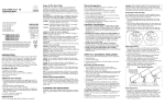
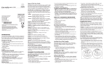
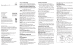
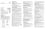
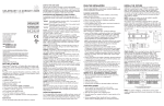
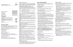
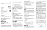
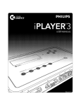
Included in This Box
•C
olorBurst 6 with accessory attachment ring
• (1) Accessory attachment spring
• (4) Screws, Phillips, 8-32 standard with color matched screw caps
for indoor junction box installations
• (4) Screws, Phillips pan head, 10-24, stainless steel, for outdoor
junction box installations.
• (1) Gasket for outdoor junction box installations
• Hex key wrench
•U
ser Guide
C olorBurs t 6
u s e r
g u i d e
Additional Items Needed
• 4” Electrical junction box (rated for your application) with
Color Kinetics Incorporated
10 Milk street, Suite 1100
Boston, MA 02108 USA
Tel 888 Full RGB
Tel 617 423 9999
Fax 617 423 9998
[email protected]
www.colorkinetics.com
ITEM# 116-000014-00
116-000014-01
116-000014-02
116-000014-03
Base: 116-000005-00
116-000005-01
•
•
•
•
•
(White, Frosted)
(Black, Frosted)
(White, Clear)
(Black, Clear)
(White)
(Black)
Scope of This User Guide
The goal of this user guide is to explain in an easily understood language the necessary steps to install ColorBurst 6 and assure peak
performance. Its intended use is for reference only, by persons who are
fully qualified. This document should never be considered a substitute
for any provisions of a regulation or state and/or local code.
This product is protected by one or more of the following U.S. Patents
and their foreign counterparts: 6,016,038, 6,150,774, 6,292,901,
6,340,868, 6,777,891, 6,788,011, 6,806,659, 6,969,954, and
6,975,079. Other patents pending.
©2003-2007 Color Kinetics Incorporated. All rights reserved.
Chromacore, Chromasic, CK, the CK logo, Color Kinetics, the Color
Kinetics logo, Color Kinetics The Leader in Intelligent Light, ColorBlast,
ColorBlaze, ColorBurst, ColorCast, ColorPlay, ColorScape, DIMand,
Direct Light, EssentialWhite, eW, iColor, iColor Cove, IntelliWhite, iW,
iPlayer, Light Without Limits, Optibin, Powercore, QuickPlay, Sauce,
the Sauce logo, and Smartjuice are either registered trademarks or
trademarks of Color Kinetics Incorporated in the United States and/or
other countries.
Identification and Warnings of Safety Hazards
PUB-000141-00 Rev. 02
Specifications subject to change without notice. Refer to www.colorkinetics.com for the
most recent version.
INTRODUCTION
Welcome to a more colorful world brought to you by Color
Kinetics. Chromacore®, our patented core technology, generates
and controls millions of colors and a variety of lighting effects
using a microprocessor to control LEDs. This User Guide contains
important information about installing and operating your new
ColorBurst® 6 fixture safely.
Fig.1
SIDE VIEW
FRONT VIEW
ACCESSORY RING
ATTACHMENT
ACCESSORY RING
LOCKING PIVOTS
BACK VIEW
ColorBurst 6 Fixture
SUPPORT ARM
SCREW CAPS
3.5-inch center to center mounting, or ColorBurst base
(Item# 116-000005) for indoor applications
18AWG, 3-conductor, stranded wire cable (when not using base)
Wire nuts
2
4VDC power supply - PDS-150e (Item# 109-000008-01) or
PDS-60 24V (Item # 109-000017-00/03)
C
ontroller - Color Kinetics DMX Controller or DMX compatible
Color Kinetics Zapi (Item# 103-000005-00, US/103-000005-01, EU)
or Serial Addressing Software (SAS)
POWER CABLE
BASE (OPTIONAL)
In accordance with ANSI Z535.4 the following system of identifying
the severity of the hazards associated with the products is used:
“danger” Imminently hazardous situation which, if not avoided,
will result in death or serious injury.
“warning”Potentially hazardous situation that, if not avoided,
could result in death or serious injury.
“caution” Potentially hazardous situation that, if not avoided, may
result in minor or moderate injury or property damage.
danger: Ensure that the main power supply is off before installing or wiring ColorBurst 6 and the power/data supply. Failure to
adhere to these instructions will result in death or serious injury.
warning: ColorBurst 6 and the power/data supply must be
installed by a qualified professional in accordance with NEC and
relevant local codes. Failure to comply can result in death, serious
injury, or property damage.
warning: Do not attempt to install or use ColorBurst 6 or the
power/data supply until you read and understand the installation
instructions and safety labels. Failure to adhere to these instructions
could result in serious injury or property damage.
warning: Do not use ColorBurst 6 if the power cables are damaged. Doing so can result in death, serious injury, and property
damage.
caution: ColorBurst 6 has no serviceable parts. Do not attempt to
open the fixture. Doing so will result in property damage and void
the warranty.
caution: Do not use sharp tools near or on the fixture lens. Doing
so will result in property damage and void the warranty.
caution: Do not hot swap. Ensure the power supply is off before
connecting or disconnecting fixtures. Hot swapping will result in
property damage and void the warranty.
note:
The instructions and precautions set forth in this user guide
are not necessarily all-inclusive, all conceivable, or relevant to all
applications as Color Kinetics cannot anticipate all conceivable or
unique situations.
Owner/User Responsibilities
It is the responsibility of the contractor, installer, purchaser, owner,
and user to install, maintain, and operate ColorBurst 6 in such a
manner as to comply with all state and local laws, ordinances, regulations, and the American Standard Institution Safety Code.
PLANNING THE INSTALLATION
The nature of a ColorBurst 6 installation requires planning to ensure
a timely, successful installation with minimal complications and
down time.
Planning Suggestions
When planning ColorBurst 6 installation, Color Kinetics suggests
doing the following:
• Consult an Electrical Inspector to approve all wiring plans.
• Refer to local and state codes for installation compliance.
• Create a Mapping Grid. Use this grid to record serial numbers
for easy reference and addressing.
• Create a Layout Plan drawing, per Lighting Designer or Architect.
• Employ Color Kinetics' Application Engineering Services.
• Get detailed wiring diagrams and additional support from
http://support.colorkinetics.com.
Installation Considerations
When creating your installation plan, consider the following:
• Location of power/data supply in relationship to lights.
• The maximum accumulated cable length for all ColorBurst 6
fixtures connected to a single PDS-150e is 400 feet. The
maximum single cable run between PDS-150e and
ColorBurst 6 is150 feet.
• The maximum cable length for a ColorBurst 6 fixture connected
to PDS-60 is 150 feet. Therefore, PDS-60 must be
located within 150 feet of the furthermost supported fixture.
• ColorBurst 6 can be installed with an optional base or with a customer-provided junction box.
• Location of fixture and method of mounting. ColorBurst 6 can be
installed indoors or outdoors on walls, ceilings, or floors. Junction
boxes and mounting methods vary according to location.
INSTALLING COLORBURST 6
Steps to a Successful Installation
1. Record serial numbers and identify fixtures as you unpack them.
2. Address the fixtures.
3.Install the power/data supplies.
4. Make electrical connections to the power/data supply.
5. Install ColorBurst 6 fixtures.
4. Using a weatherproof label, identify the fixtures installation position based on the Layout Plan. Place the identifying label in an
inconspicuous location noting the order or placement in the installation. This step not only minimizes installation mistakes, but aids
in post-installation light show programming.
Addressing the Lights
important:
Before you begin the installation, consider the scope of
your lighting application and installation. Your ColorBurst 6 is set
to DMX address one (1) at the factory. If your application requires
other addresses, set the DMX addresses before installing
ColorBurst 6 using one of the following addressing tools:
zapi:
Use Color Kinetics' Zapi to set the DMX address for each
fixture or set all fixtures to the same DMX address. Refer to the
Zapi User Guide for step-by-step addressing instructions.
sas (serial addressing software): Use a PC with iPlayer 2, or a
PC with Smart Jack 3 to address the fixtures. Download SAS and
instructions from www.colorkinetics.com/support/downloads.
note: For applications using multiple, daisy-chained power supplies,
you can address all lights in the chain by attaching Zapi to the first
power supply in the series.
note:
Multi-power supply setups are ideal for pre- and post-installation. For post-installation addressing, record all serial numbers and
layout positions prior to installation.
Setting Individual Addresses
Using the Serial Number mode of Zapi 1.5 or SAS, address each
fixture attached to a power supply or a series of connected power
supplies individually.
1. With power disconnected, connect up to six ColorBurst 6 to the
power/data supply.
2. A
ttach the DMX interface (Zapi, iPlayer 2, or Smart Jack 3) to the
DMX IN port on the power/data supply.
3. C
onnect power to the power/data supply.
4. Use Zapi or SAS to set the light address of each fixture.
5. D
isconnect power and then disconnect the addressed ColorBurst
6 fixture(s).
6. Repeat steps 1 through 5 for all remaining fixtures.
7. After all fixtures are addressed, disconnect the DMX interface.
Setting the Same Address to Multiple Lights
Using Zapi 1.5, address all fixtures attached to a power supply or
multiple, daily-chained power supplies.
1. With power disconnected, connect up to six ColorBurst 6 fixtures
to the power/data supply.
2. A
ttach the Zapi to the DMX IN port on the power/data supply.
3. C
onnect power to the power/data supply.
4. Use Zapi to set the light addresses. All ColorBurst 6 fixtures connected to the power/data supply are addressed simultaneously.
note: If you are using SAS, you must input each serial number
(address) separately.
5. Disconnect the DMX interface.
Recording Serial Numbers
Installing the Power/Data Supply
1. As you unpack the fixtures record the serial numbers.
Each ColorBurst 6 has a unique serial number programmed at
the time of manufacture.
2. Write the serial numbers onto a Mapping Grid or use a bar code
scanner along with Color Kinetics Serial Addressing Software
(SAS) to record each serial number. SAS and instructions are
located at www.colorkinetics.com/support/downloads.
3. Using the Layout Plan, assign the fixture to a layout position in
the installation.
Following the Layout Plan, install the power/data supply according to
state and local codes. Refer to the PDS-150e or PDS-60 24V Installation
Guides for complete instructions.
Making Electrical Connections to the
Power/Data Supply
After installing the power/data supply, make the electrical connections to it.
1. Pull the 3-conductor cable from the optional base or the
18 AWG, 3-conductor, stranded wire cable from the junction box
to the power/data supply. When using the ColorBurst base, pull
the base cable from the fixture location to the data/power
supply.
2. Pull the cable through the knock-outs in the side of the power/
data supply.
3. Wire the red, white, and black wires of each fixture to a provided connector, then snap connectors into the connector terminals
located in the power/data supply. (See Fig. 2.)
Fig. 2
COM
BLACK
DATA
24V
WHITE
RED
Fig. 4
60-foot (18.3 m)
power/data cable
included with optional
mounting base
Connecting Power
Follow the instructions in the PDS-150e or PDS-60 Installation Guide
to connect from a 100 to 240VAC power source.
warning: Ensure that power is off before wiring or connecting
fixtures to the power/data supply. Failure to do so can result in
serious injuries or death.
caution: Do not overload the power/data supply. Doing so will
result in property damage and void the warranty.
note: Each ColorBurst 6 receives power directly from a power
supply.
Connecting the Fixtures using a Junction Box
ColorBurst 6 with PDS-60 (Preprogrammed)
Power/Data Cable
18AWG/.823mm2 CSA,
3-conductor, stranded copper
Maximum cable run from
60W Power/Data Supply
to Lights: 150 feet (46 m)
DMX
OUT
DMX/ETHERNET
IN
After pulling the 3-conductor, stranded wire cable from the power/
data supply to the indoor rated junction box, connect wire leads
from the fixture to the junction box using medium wire nuts. Connect
the red wire to the +24VDC, white wire to Data, and black wire to
Common.
note: The fixture wire leads are 6-inches long and can be trimmed
as necessary. The color connections must correspond to color connections on the power/data supply.
Indoor: Junction Box Mount
1. After wiring the fixtures, neatly tuck the conductors into the junction box.
2. Insert two fastening screws included with ColorBurst 6 through
the holes in the canopy assembly, then through the mounting
holes in junction box, and tighten. (See Fig. 7.)
3. Cover screw heads and open canopy holes with screw caps.
Color Kinetics
Controller
(CAT5/RJ45)
100-240VAC
PDS-60
Maximum: Two ColorBurst 6 fixtures per PDS-60 power/data supply.
Fig. 5
Fig. 7
ColorBurst 6 with PDS-60 24V (DMX Control)
DMX IN
(CAT5/RJ45)
caution:
When not using the base, you must provide an 18 AWG,
3-conductor, stranded copper cable. Failure to provide the proper
cabling can result in damage to the fixture and void the warranty.
DMX IN
Installing ColorBurst 6
3.5" ON CENTER
MOUNTING HOLES
WALL/CEILING
*SHADED ITEMS NOT INCLUDED
*SHADED ITEMS NOT INCLUDED
100-240VAC
DRAIN FEATURE
PDS-60 (DMX/Ethernet)
RETENTION SPRING
DMX OUT
DMX IN
(CAT5/RJ45)
DMX IN
Outdoor: Junction Box Mount
1. After wiring the fixtures, neatly tuck the conductors into the junction box.
2. Insert four fastening screws through the holes in the canopy
assembly, then through gasket, into the mounting holes in junction
box, and tighten. (See Fig. 8.)
3. Cover screw heads with screw caps.
DMX
Controller
24V for Accessory
Controller (as required)
DMX OUT
ETHERNET
Fig. 8
Fig. 3
ColorBurst 6 with PDS-150e
WALL/CEILING
100-240VAC
Power/Data Cable
18AWG/.823mm2 CSA, 3-conductor, stranded copper.
From PDS-150e Power/Data Supply maximum accumulated length
of cable run for all fixtures must not exceed 400 feet (122 m).
(Power/data cable for junction box-mount provided by third party.)
Maximum single run distance from PDS-150e: 150 feet (46 m).
PDS-60 (DMX/Ethernet)
4-INCH OUTDOOR
ELECTRICAL
JUNCTION BOX *
GASKET *
Fig. 6
ColorBurst 6 with PDS-60 24V (Ethernet Control)
OUTDOOR
10-24 MOUNTING SCREW
DMX OUT
Ethernet IN
ETHERNET
+24V
GND
ETHERNET
24V
DATA
COM
24V
DATA
COM
24V
DATA
COM
Ethernet
Switch
PDS-60 (DMX/Ethernet)
FUSE
24V
DATA
COM
24V
DATA
COM
PDS-150e
Power/Data supply
100-240VAC
DMX IN
DMX OUT
Ethernet IN
Light
System
Engine
PC*
ETHERNET
DIAGNOSTIC
INDICATOR
LIGHTS
CAT 5/RJ45
Data Cable
*SHADED ITEMS NOT INCLUDED
Power/Data Cable
18AWG/.823mm2 CSA,
3-conductor, stranded copper
Maximum cable run from
60W Power/Data Supply
to Lights: 150 feet (46 m)
+24V
GND
Color Kinetics
Controller
DMX IN DMX DMX OUT
LOOP REPEATER
OUT
FUSE
FUSE
24V
DATA
COM
(Junction box not included)
AUX IN
Maximum: Six ColorBurst 6 fixtures per PDS-150e Power/Data supply. (One per terminal.)
Note: Do not daisy-chain ColorBurst 6 fixtures.
60-foot (18.3 m)
power/data cable
included with fixture.
AIMING THE FIXTURE
Fig. 9
Positioning ColorBurst 6 is simple with the dual
swivel, aim-and-lock feature. (See Fig. 9.)
1. After installing and energizing the light,
rotate the fixture arm to the desired position.
2. Using the provided Hex key wrench, tighten
the locking set screw located on the base to
lock the arm in place.
ACCESSORY RING
ATTACHMENT SCREWS
IMPORTANT INFORMATION
Strobe Warning
There is some anecdotal evidence that strobe lighting may induce epileptic symptoms in certain susceptible individuals, although no associated product warnings
have been issued by United States government according to the Food and Drug
Administration.
If strobe lights are used, some international regulatory agencies1 recommend
keeping flicker rates at or below four flashes per second (as less of the flicker-sensitive population will then be at risk of an attack). This flicker rate applies only to
the overall output of any group of lights in direct view. However, when more than
one strobe light is used, the flashes should be synchronized. End users should also
consider issuing a warning, alerting audience or viewers to the
presence of strobe lighting.
For protection from extreme temperatures, ColorBurst 6 has been designed with a
temperature monitoring feature. If operating temperatures rise to an unsafe level,
a compensation circuit is triggered and the ColorBurst 6 operation is interrupted
causing the lights to turn dull red. After 30 minutes the lights will auto-cycle and
return to full intensity.
To prevent additional power shut-downs, determine the cause of the overheating
and correct the problem.
If any problems occur during usage, unplug the product immediately and call or
email:
Color Kinetics Technical Support Group:
1-888-FULL RGB or 617-423-9999 or [email protected]
0˚
35
˚
0
5
3
PDS-60 (DMX/Ethernet)
* PC used for show
authoring and show control.
OPTICAL ACCESSORY*
Temperature Monitoring
SCREW CAP
DMX IN
(60-foot power (18.3 m)/data cable
included with optional
mounting base.)
To install accessory louvers, filters, or lenses:
1. Remove the three attachment screws from the fixture housing. The
attachment ring will separate from the fixture housing.
2. A retention spring retains the accessory securely to the accessory
ring. Squeeze the spring to remove it from the ring.
3. Place the accessory into the ring.
4. Replace the spring to hold the accessory in place while reattaching the ring to the housing.
5. Align the through holes on the accessory ring with the screw
holes on the fixture housing, ensuring the drain features align.
Replace the attachment screws. (See Fig. 10.)
SCREW CAP
60-foot (18.3 m)
power/data cable
included with fixture.
The ColorBurst 6 fixture can be connected using either the optional
base or a junction box. For details on installing the fixtures with the
optional base, see the ColorBurst Base Installation Guide.
Fig. 3 shows the ColorBurst fixtures connected to the PDS-150e. Fig.
4 shows fixtures connected to the PDS-60 with Preprogrammed control. Fig. 5 shows fixtures connected to the PDS-60 24V with DMX
control. Fig. 6 shows fixtures connected to the PDS-60 24V with
Ethernet control.
ColorBurst 6 is designed to accommodate louvers, filters, and lenses
with a maximum 6-inch outer diameter and up to 3/16-inch thick.
8-32 MOUNTING SCREW
+24V
GND
Power must be off before installing ColorBurst 6.
ColorBurst 6 can be installed indoors or outdoors. Use an electrical
junction box rated for your application for wall and ceiling mounts.
warning:
Power/Data Cable
18AWG/.823mm2 CSA,
3-conductor, stranded copper
Maximum cable run from
60W Power/Data Supply
to Lights: 150 feet (46 m)
USING ACCESSORY LENSES
Fig. 10
DMX OUT
ETHERNET
This fixture shall be installed by a qualified professional in accordance with NEC and relevant local codes for Class 2 power
sources.
INDOOR ELECTRICAL
JUNCTION BOX *
3. Rotate the fixture and lock it into place by tightening the set
screw located on the arm.
note: Each swivel provides a 350˚ turning radius with hard stops to
prevent over rotation.
caution: Do not force hard stops to over rotate. Doing so will damage the fixture and void the warranty.
caution: Do not over tighten set screws.
1G
uide to Health, Safety and Welfare at Pop Concerts and Similar Events,
HMSO Publications (UK)
ColorBurst 6 specifications
color range
source
beam angle
packaging
connectors
listings
protection rating
data interface
control
power requirement
power consumption
power supply
temperature range
16.7 million (24bit) additive RGB colors; continuously
variable intensity output range
High intensity power LEDs
12˚ clear lens, 22˚ ground lens
Die cast aluminum in black and white finish
Unified power and data cable
UL/cUL Listed, CE
IP66
Color Kinetics data interface system
Color Kinetics full line of controllers or DMX512 (RS485)
compatible when using Color Kinetics power/data
supply
24VDC
25W Max. at full intensity (full RGB)
PDS-150e - Maximum of six fixtures per supply
PDS-60 24V - Maximum of two fixtures per supply
-40°F to 122°F (-40°C to 50°C) operating temperature
-4°F to 122°F (-20°C to 50°C) starting temperature
LED Source Life
In traditional lamp sources, lifetime is defined as the point at which 50% of the lamps
fail. This is also termed Mean Time Between Failure [MTBF]. LEDs are semiconductor
devices and have a much longer MTBF than conventional sources. However, MTBF is
not the only consideration in determining useful life. Color Kinetics uses the concept
of useful light output for rating source lifetimes. Like traditional sources, LED output
degrades over time (lumen depreciation) and this is the metric for SSL lifetime.
LED lumen depreciation is affected by numerous environmental conditions such as
ambient temperature, humidity, and ventilation. Lumen depreciation is also affected by
means of control, thermal management, current levels, and a host of other electrical
design considerations. Color Kinetics systems are expertly engineered to optimize LED
life when used under normal operating conditions. Lumen depreciation information is
based on LED manufacturers’ source life data as well as other third party testing. Low
temperatures and controlled effects have a beneficial effect on lumen depreciation.
Overall system lifetime could vary substantially based on usage and the environment in
which the system is installed.
Temperature and effects will affect lifetime. Color Kinetics rates product lifetime using
lumen depreciation to 50% of original light output. When the fixture is running at room
temperature using a color wash effect, the range of lifetime is in the range of 80,000100,000 hours. This is LED manufacturers’ test data. High output is defined as any LED
device that is 1/2 watt or above. For more detailed information on source life, please
see www.colorkinetics.com/lifetime.
warranty
This product is sold pursuant to CK’s Standard Terms and Conditions (the “T&Cs”) which
may be found at http://colorkinetics.com/howtobuy/buy/terms and which contain
important provisions, including, among others, Limited Warranty, exclusions and limitations on CK’s liability for damages, and restrictions on the remedies that are available
to you.