1
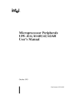
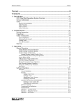
United States Patent [191
[11]
4,323,242
Rosenfeld
[45]
Apr. 6, 1982
[54] ELECTRONIC MAZE GAME
[76] Inventor:
FOREIGN PATENT DOCUMENTS
Peter E. Rosenfeld, 149 Mountain
Ave., Berkeley Heights, NJ. 07922
[21] Appl. No.: 189,583
2040695
9/1980
United Kingdom .......... .. 273/1 GE
Primary Examiner-Vance Y. Hum
[57]
ABSTRACT
An electronic maze game comprising a maze which is
[22] Filed:
Sep.23, 1980
[51]
Int. Cl.3 .............................................. .. A63F 9/06
[52]
U.S c1 .................... .. 273/153 R; 273/1 GC
[58]
Field of Search .............. .. 273/1 GC, 1 GE, 1 E,
273/153 R, 138 A, 237, DIG. 28; 434/201;
364/410, 411
[56]
References Cited
U.S. PATENT DOCUMENTS
4,051,605 10/1977
Toal et a1. ......................... ,. 434/201
4,103,895 8/1978
4,126,851 11/1978
Pressman et a1. .
..
Okor ......................... .. 273/237
4,240,638 12/1980 Morrison et al
4,249,734
4,275,443
2/1981
6/1981
273/153 R
Bromley ...................... .. 273/94
Sorin ................................. .. 273/237
stored electronically in the memory of a microcom
puter, a four bar display which indicates if there is a
wall or an opening immediately above, below, right or
left of the player’s present position, and four push but
tons which permit the player to make a move from his
present position to the adjacent position lying above,
below, to the right or left, provided that such move is
not blocked by a wall. A number of different mazes are
stored in the game, and the player may choose to play a
“beginner”, “intermediate” or “advanced” game, or
repeat the last game played. A two digit display tells the
player at the beginning of the game the minimum num
ber of moves required to transit the maze, and during
play of the ‘game, the number of moves the player has
made.
8 Claims, 4 Drawing Figures
US. Patent
Apr. 6, 1982
Sheet 1 of3
FIG. 3
ROWS
23
COLUMNS
4,323,242
US. Patent
FIG
Apr. 6, 1982
Sheet 3 of3
4 -
4,323,242
' START
EE'BEJK
CLEAR MOVES ONTR
wAn FOR |00 Ms
A MOVES REG
"
A
40o
/40[
,
RNTN N0 BUTTONS
1
_
—-
ENABLE El.
PUSHED
GLEAR FOUR BAR
-
‘
DISPL_AMY__K,__
WAIT FOR A
_
BUTTON PUSH
402
‘
sET sELEcT
MAZE FLAG :“4'4
403
GENERATE
YES
SEL IP?AZE
40s
N0
\)
IONNTEHéJLPET
TNGREMENT
3
4'5
AARERL
TRANSFER
404
A
RESULTS To
405
MovEs REG
GLEAR sELEGT
MAzE FLAG
1
ENTER UPON
'"TERRUPT 42'
cALGuLATE NEN
.
GAME NuMBER
-
’\ 4'6
N0
,
4n
\
401
MALT PLAY G 3
BLANK FOUR BAR
DLSPLAY
TRANSMH' NEW
GAME NuMBER
WA" FOR &
oEvNEDR IONATBEL§RUK|LDT
RECEIVE NEN GAME
GET START 8‘ END
GET mm L END
CELL LOGS &
MIN No. MovEs
FROM TABLE
LNITIALIZE DISPLAYS
FOR NEN GAME
l
RETuRN FROM
\NTERRUPT
-
MAKE MOVE
409/‘ A DISPLAY
'\-41@
NEW‘CELL
RN BANNER
'
FROM TABLE
‘
1
N0
No
PUT MLN N0.0F
YES
M°V%SEGT'§'TEM;?VES “/ 4'9
4N-/~
l
DISPLAY FIRST
CELL OF ME
_
p420
END0'5"”
sYNBoL
A
GENERATE
4|g-/~ INTERRUPT
0N GABLE
Ala
E
WAIT FOR
sELEcT
MAzE BuTToN
TO BE
PUSHED
4,323,242
1
2
FIG. 4 is a ?owchart of a computer program which
ELECI‘RONIC‘MAZVE GAME
may be stored in and executed by the electronic cir
cuitry of FIG. 2 in the practice of my invention.
SUMMARY OF vTHE‘INVENTION
This relates to a game in which one or more players
try to work their way out of a maze in a minimum
BEST MODE OF CARRYING OUT THE
INVENTION
FIG. 1 depicts an electronic maze game 100 of my
length of time, or in a minimum number of moves, using
invention
as it would be packaged in a hand held case.
a display which shows them only the structure of the
‘Shown in the middle is a four bar display 107 compris
maze in their immediate vicinity.
10 ing a bottom bar 108, a left bar 109, a top bar 110 and a
In a prefered embodiment of the invention, a four bar
right bar 111. To the left of the four bar display is an
display, arranged in the shape of a square, indicates if
On/Off switch 101. To the right of the four bar display
there is a wall or an opening immediately above, below,
is a Select Maze push button 102. Below the four bar
right and left of the player’s present position. Four push
display are four move push buttons, a Move Down
buttons are used by the player to make a move from his
present position to the adjacent position lying above,
button 103, a Move Left button 104, a Move Up button
105, and a Move Right button 106. These same four
buttons are used immediately after the Select Maze
button 102 has been pressed to select a beginner, inter
below, to the right or left, provided that such move
ment is not blocked by a wall. A two digit display tells
the player at the beginning of the game the minimum
mediate, or advanced level game or a repeat of the last
number of moves required to transit the maze, and dur 2,0 game played, respectively. Shown above the four bar
ing play of the game, the number of moves the player
display is a two digit Seven Segment display 112 which
had made.
is used immediately after a game has been selected to
A number of different mazes are stored in the game,
display the minimum number of moves to solve the
and the player may choose to play a “beginner”, “inter
particular maze, and is used after the ?rst move has been
mediate”, or “advanced” game, or repeat the last game 25 made to display the number of moves the player has
played. In its present embodiment, the game contains
made. In thevupper right hand corner is a jack 113 used
four beginning, four intermediate and eight advanced
to connect to similar other maze games (not shown)
mazes, and a random number generator is used to select
over a two conductor cable (not shown). At the top of
the particular maze from within the category the player
the case is shown a picture 114 of one of the 16 mazes
has chosen.
stored in the memory of the game, in particular, one
that can be selected by pressing the Select Maze and
‘
When the game is played by a single player, the ob
ject is to complete it in the minimum number of moves,
Move Right (Repeat Game) buttons immediately after
which means that the player will normally repeat a
turning on the On/Off switch. This maze is pictured on
particular maze a number of times, trying to improve his 35 the case as an aid to a ?rst time user of the game, to help
performance by avoiding dead ends or circituitous
him understand its operation.
paths encountered on previous tries. For play by more
than one person, provision is made for connecting two
or more units together using a signaling cable, which
how to implement the game with a particular set of
FIG. 2 is an electrical schematic diagram showing‘
electronic components, in particular an Intel Corpora
tion 8748 microcomputer integrated circuit 200 and a
Hewlett. Packard Corporation two digit seven segment
play on all units when any player completes the game.
display. The reader who is not familiar with the opera
At the moment that the game is won, the winner’s dis
tion of the Intel Corporation 8748 microcomputer is
play shows all four bars, and the losers’ displays show
refered to the Intel Corporation publication “MCS-48
no bars. The winner is now allowed to select the next
game to be played, and as soon as it is transmitted over 45 MICROCOMPUTER USER’S MANUAL”, copy
right 1978. For convenience, elements common to
the cable to the other units, play resumes. The ability to
causes all units to display the same maze, and to halt
connect a number of units together over a cable is con
sidered an important feature of this game, as it allows a
number of players to make moves simultaneously rather
than in sequence as is usual in games for multiple play
ers. This may make the game more exciting to children
FIGS. 1 and 2 are identi?ed by the same numbers. It is
to be understood that this game could be implemented
with microcomputers and displays manufactured by
others, but a different wiring diagram would result.
In a preferred embodiment of my invention each
maze is a two-dimensional square maze, and 16 such
mazes are stored in a table in the memory of the micro
game to be played by people in different rooms, which
processor. Four of these mazes are beginner level 4X4
may also have appeal to children.
_
i '
‘
55 mazes, four are intermediate level 6 X 6 mazes, and eight
are advanced level 8X8 mazes. An illustrative such
BRIEF DESCRIPTION OF THE DRAWINGS
8 X 8 maze 'is shown in FIG. 3.
These and other objects, features, elements and ad
To store the maze, and determine movement through
vantages of my invention will be more readily apparent
the maze, each maze is regarded as composed of m by 11
who get impatient waiting for a mm. It also allows the
from the following detailed description of the invention
in" which: FIG. 1 is a depection of an illustrative em
bodiment of my‘ invention, packaged in a hand-held
case;
FIG. 2 is a schematic diagram of electronic circuitry
cells and each cell is represented by a number having
the from a,b where a represents the column in which the
cell is located and b represents the row. For conve
nience, the rows and columns of the 8 X 8 maze of FIG.
3 are numbered, and the corner cells are designated 0,0
suitable for implementing the illustrative embodiment 65 0,7 7,7 and 7,0 proceeding clockwise from the lower
of FIG. 1;
'
‘ ~
FIG. 3 is an illustrative example’of a maze which ma
be played with the embodiment of FIG. 1;‘and
lefthand corner. The designation of the other cells will
be apparent. A player’s position in the maze can there
fore be represented by the number a,b of the cell where
3
4,323,242
4
binary notation for each dimension of each cell whether
402 where the program loops until it detects the opera
tion of one of the aforementioned push buttons 102-106.
Below this is a Disable Program Interrupt (P.I.) block
403 where the program disables the External Interrupt
there is or is not a wall in the direction of forward or
circuitry used to detect signals arriving via jack 113
the player is; and this number can be stored by one or
more registers of microprocessor 200.
The maze itself is stored in a table which indicates in
backward movement from that cell in that particular
from another unit. It is convenient to postpone recog
dimension. This table can be stored in a number of
ways. To minimize storage requirements, I store only
nizing these signals during the few milliseconds neces
sary to respond to a local button being pressed. Next,
one representation of each wall in the maze; and to
follows a Test block 404 where the program branches
facilitate processing, I store together the binary repre
left if the “Select Maze” button 102 was pressed, and
right if one of the four “Move” buttons 103-106 was
pressed. In the latter event, a second test 405 is made to
determine if a normal move is called for, or if the Move
FIG. 3 are represented electronically in the memory of
buttons are presently being used to select a new game.
the microprocessor 200 by the binary number
100111101; and the walls in row 1 of the maze of FIG. 15 This test is done upon a flag set in a portion of code yet
3 are represented electronically by the binary number
to be described. If a normal move is called for, the
111110111. As will be apparent, nine binary digits are
program proceeds to a block 406 which represents the
code necessary to increment a register used to keep
needed to represent the nine walls in a row or column of
track‘of the number of moves made during the present
an 8X8 maze, but since the maze is assumed to have a
game, and transfer the results to the register used to
continuous outer wall, there is no need to represent the
drive the two digit seven segment display. Next comes
?rst or last of these walls in memory.
a test block 407 wherein the validity of the requested
During play, the con?guration (i.e. the presence and
move is determined. The state of the four bar display is
absence of walls) of the cell in which the player is then
examined to determine whether or not a wall segment is
located is constantly displayed by four bar display 107
with lighted bars 111, 109 representing the presence of 25 indicated that would block the designated move.
walls in the forward and backward directions of one
Should the move be invalid, the program returns via an
Enable P.I. block 408 to the Wait block 401. In the case
dimension, and lighted bars 110, 108 representing the
presence of walls in the forward and backward direc
of a valid move, the program proceeds to a Move and
sentations of all the walls in a particular row or column
of the maze. Thus, the walls in column 1 of the maze of
tions of the second dimension. Advantageously this
display is controlled by a register into which the micro
processor has loaded the binary information from the
maze table which indicates the presence or absence of a
Display block 409 wherein the data describing the next
cell in the maze is retrieved from a table of maze data
and used to update the four bar display. Next, a test 410
is made to determine if the maze cell just entered is the
end of the maze. If the test 410 indicates it is not the last
wall in the forward and backward directions in each
dimension at the cell where the player is then located.
cell, the program returns via the Enable P.I. block 408
Thus, if the player is located in cell 2,3 of the maze of 35 to the Test block 401. However, if the test 410 deter
mines the cell just entered is the last in the game, the
FIG. 3, the processor reads from memory the binary
program proceeds to a display block 411 which causes
number 10000110, representative of the walls of row 3,
and shifts this number two digits to the left to read the
all four bars of the four bar display to be illuminated,
thus signaling the end of the game. Next follows a gen
binary number 0,0 from the two most signi?cant bits,
indicating there are no walls on the left and right hand 40 erate interrupt block 412 where the program causes a
signal to be sent via jack 113 to other units 100, inform
sides (the backward and forward direction in one di
ing them that they have lost the game. There follows a
mension) of cell 2,3. In like fashion, the processor also
wait block 413 where the program loops waiting to
reads from memory the binary number 10011111 repre
detect the pressing of the Select Maze push button.
sentative of the walls of column 2, and shifts this num
ber three digits to the left to read the binary number 1,1 45 Next comes a Set Flag block 414 in which the ?ag
tested in the test block 405 is set. This block 414 may
indicating there are walls at the top and bottom (the
also be entered from a Generate Interrupt block 415
forward and backward directions in the second dimen
which places the signal that halts play on the cable used
sion) of cell 2,3. This information is provided to the
register which controls the display.
~
to interconnect two or more game units.
Returning now to the Select Maze Flag test 305 we
Movement through the maze is a matter of moving to
the adjacent cell by incrementing or decrementing ei
will examine the path taken if the ?ag is set, thereby
ther the value of a or the value of b of the number a,b
indicating that a new game is in the process of being
selected. First comes a Clear Flag block 416 which
clears the flag just tested in test block 405. Next comes
representing the cell where the player is. These steps
are controlled by buttons 103-106. However, before a
change in cell position can be made, the validity of the 55 a Calculate New Game Number block 417 where a
number obtained from a random number generator
move must also be tested by checking for the absence of
routine is used in conjunction with information about
a wall in the direction of the move. Advantageously,
‘which of the four move buttons 103-106 was pressed, to
the data that controls the display is used to test the
validity of the move. FIG. 4 is a ?ow chart of the pro
select a new beginner, intermediate or advanced game
gram stored in and executed by the microcomputer 200 60 number, or repeat the last game number. This is fol
in FIG. 2. At the top is shown an initialize block 400
lowed by a Transmit block 418 where the previously
which represents the code used to initialize the various
selected game number is transmitted in a pulse code
registers, ?ags, and Input/Output (I/O) ports used later
format over the cable used to interconnect two or more
in the program. Below this is a Wait block 401. where
game units. This block also contains the code to end the
the program loops until it detects a continuous period of 65 program interrupt initiated either in block 412 or 415,
100 milliseconds during which none of the ?ve push
and the code to get from the maze table the information
button switched 102-106 are operated, and thus serves
to “debounce” the switches. Below this is a Wait block
about the start, end, minimum number of moves to
transit the game just selected in block 417. Next comes
5
‘6
a block 419 in which the information about the mini
interconnecting cable. This block also contains code to
initiallize the four bar display 107 and the seven segment
display 112 for the beginning of the new game. The
purposes of the other blocks in FIG. 4 will be apparent
mum number of moves to transit the maze is sent to the
seven segment display 112, and a display block 420
where the data de?ning the walls of the starting cell is
sent to the four bar display 107.
Also shown in FIG. 4 is an Interrupt Service block
to one skilled in the art of computer programming.
As will be apparent to those skilled in the art, numer
ous variations may be made in the above described
421 which is entered if an interrupt is received over the
interconnecting cable. This code halts play and blanks
game and method of play that are within the spirit and
scope of the invention. While the game described above
the four bar display 107 to indicate that a player at
another game unit has completed the maze and there
fore won the game. Additional code then waits for and
receives the game number for the next game to be
played, when it is transmitted in pulse code over the
is a two dimensionalmaze game, expansion of the game
to mazes of three and more dimensions will be apparent
to those skilled in the art.
*MICROMAZE - Version 4 - Added code for moves counter & cable interrupts
‘Data in page 3, 16 bytes per maze, 16 mazes.
‘First 8 bytes are horiz bar info, MSB is bottom bar,
‘first byte is for X = 0 column.
‘Next 8 bytes are vert bar info, MSB is left bar,
‘first byte is for Y = 0 row. 7
' '
‘Start and Stop locations in top of page 2, 2 bytes/game.
‘Even addr. has Start 100., MS nibble = X, LS = Y
‘Min. # moves/game in BCD in page 2 starting at ZdO
‘r7 = XYend for present game
,
"r6 = pointer to data base addr for present game
‘r2 = complement of bus, i.,e.state of 4 bar display
“r0 & r1 are scratch pads used in button debounce.
*RBl assignments - r7&4 save AC r5&6 number of moves
‘P2 drives 7 seg. disp. - bits 6 to 0 = segments a to g
‘P2 bit 7 connects to INTerupt for cable driver
‘Pl bits 7 & 6 drive cathode 2 and 4&5 cath. 3 (Cl doesnt exist)
‘Pl bits 0,l,2,3 read switches rt 1f dn up
‘TO reads reset sw
‘Bus drives 4 bar disp. bits 0&4 top 1&5 bot, 2&6 it, 3&7 1ft
*To get vert bars, add 8 to Y value plus maze base addr
‘to get addr of bye to be shifted left X times. Bits
*7 and 6 then de?ne state of vert bars.
‘To get horiz bars, add X value ot maze base addr to form
‘address of data byte which is then shifted left Y times.
‘Then use bits 7 and 7 (7 is bot bar).
org
clr
a
jmp
init
org
3
jmp
intr
‘Display BCD # in RBI r6, different digit each time clk ticks
org
msd
callx
clkret
sel
rbl
mov
r7,a
save ac
in
jb7
a,pl
msd
Which digit is displayed now?
mov
a,r6
display LSD
call
mov
xlate
a,#0cfh
Select cathode 3
outl
jmp
pl,a
clkret
mov
a,r6
swap
a
anl
a,#0fh
jnz
callx
mov
a,#0ah
call
xlate
mov
a,#3fh
outl
pl,a
mov
a,#0c0h
mov
mov
retr
t,a
a,r7
Test for leading zero
10 = blank
,
.
Select cathode?
Restore ac
"Xlate subroutine - BCD to 7 seg.
xlate
anl
a,#0fh
add
a,#xbase
in
a,p2
anl
a,#80h
outl
p2,a
ret
Mask off left digit
Combine 7 seg data with P1 bit
'
v " 4,323,242
7
‘continued
xbase
db
db
db
db
db
db
db
db
db
db
db
7eh
30h
6dh
79h
33h
Sbh
lt‘h
70h
7m
73h
0h
‘interrupt routine - used when cable connects several units
‘Signals end of game (you loose) and next game number
intr
iwait
ihere
sel
rbl
mov
sel
r7,a
rbO
clr
a
cpl
a
outl
bus,a
mov
r3,a
Save AC
blank the box display
mov
a,#8eh
outl
p2,a
in
cpl
a,p2
a
Wait for new game number
jb7
iwait
Jump if interrupt still at gnd
inc
r3
Incr. new game no. cntr.
mov
djnz
rl,#60h
rl,ihere
Wait
to see if inter. has ended
in
a,p2
cpl
a
ib7
iwait
call
xyss
call
displa
sel
rbl
mov
a,r7
Set 7 seg. display to L
Jump if inter. still in progress
‘
Restore AC
retr
‘Program starts here
init
sel
rbl
mov
r6,a
sel
outl
cpl
rbO
bus,a
a
Initialize display to check battery
mov
r2,a
set r2 to “box"
mov
(AC is already 0)
r3,#4
Select opening game
strt
t
Start random number generator
start
en
en
tcnti
i
start2
wait
mov
djnz
r0,#20h
rl,wait
jntO
in
start2
a,pl
nobut
cpl
a
anl
jnz
a,#0fh
start2
djnz
r0,wait
jntO
reset
in
a,pl
Test for button pressed
cpl
a
an]
jz
a,#0fh
nobut
dis
j?)
i
newgam
sel
rbl
Increment # moves counter
mov
mov
r4,a
a,r5
save AC
add
a,#1
da
a
mov
mov
mov
r5,a
r6,a
a,r4
rbO
sel
up
wait for 200 ms of no buttons
jb3
up
jb2
dn
jbl
lt
jbO
rt
jmp
mov
jbO
inc
start
a,r2
start
r4
Jmp
out
Test for game selection
restore AC
continuing game, get dir. of move
.
hardware error if you get here
valid move?
jmp if no
yes
10
-continued
dn
It
rt
out
me
reset
newgam
beg
int
adv
setss
xloop
.
mov
a.r2
jbl
start
dec
jmp
mov
jb3
dec
r4
out
jmp
out
a,r2
start
r5
mov
a,r2
jb2
start
inc
r5
call
displa
mov
a,r5
swap
a
Test for end
add
xrl
a,r4
a,r7
jnz
strt
Keep going
clr
a
End
outl
bus,a
Display box
cpl
mov
a
r2,a
anl
p2,#7fh
Generate interrupt
jtO
dis
me
i
Wait for reset button
anl
p2,#7fh
Generate interupt
clr
?)
cpl
?)
Set ?ag
clr
sel
mov
mov
sel
mov
cpl
a
rbl
r5,a
r6,a
rbO
r2,a
a
Clear Display
outl
jmp
bus,a
start2
clr
jbO
10
setss
jbl
int
jb2
beg
clr moves cntr and register
Clear reset ?ag
repeat last game
jb3
adv
jmp
start
error if pgm gets here
mov
a,t
Get random number
anl
a,#3
Mask'it
mov
r3,a
jmp
setss
mov
a,t
anl
orl
a,#3
a,#4
mov
r3,a
jmp
setss
mov
a,t
anl
orl
a,#7
a,#8
mov
mov
ids
mov
inc
r3,a
a,r3
tcnti
orl
p2,#80h
djnz
r0,kt
Add offset
Xmit game #
r0,a
r0
en
tcnti
call
xyss
call
displa
jmp
start
clear interrupt
kt
mov
rl,#40h
time delay for game # xmit routine
kt2
djnz
anl
rl,kt2
p2,#7fh
Set interrupt
mov
rl,#40h
kt3
djnz
rl,kt3
jmp
xloop
‘Display subroutine
displa
mov
a,r5
VERT BARS - set up cntr
Get Y
add 8
add data table base addr
get data word
set carry
cpl
c
11
4,323,242
-continued
rrc
rlc
rotate X times
djnz
an]
horiz
mov
Get 2 bits
Save them
mov
HORIZ BARS - set up cntr
mov
inc
Get X
add data table base addr
mov
add
movp3
clr
hrot
cpl
C
rrc
a
rlc
djnz
anl
rr
rr
add
mov
swap
add
mov
cpl
out]
disret
ret
‘XYSS subroutine -
org
xyss
gets Xystart, xyend, & min. # of moves from page 2
200h
mov
a,r3
1']
inc
add
a
form xyend
movp
get byte
mov
Save it
mov
fonn start 100.
rl
add
movp
mov
swap
an]
mov
mov
anl
mov
mov
Get min # of moves
add
movp
sel
mov
mov
sel
mov
swap
mov
ret
end
2d0: 9 9 813 21131618
28 32 32 20 37 35 25 3O
032032310300
0520451505045
30271274075327
760175277227
98d898a80000
98e8a8880000
9098d8‘a80000
a8e8c8880000
8828a8c80000
e8a8d8a80000
c8b8a8c80000
28a898a80000
l2bafel‘2ead200
c282868ad6ca00
92fece8edcaa00
969aaa92828600
Multiply game # by 16
12
13
4,323,242
14
-continued
What is claimed is:
1. An electronic maze game comprising:
4. The electronic maze game of claim 3 wherein the
display elements are liquid crystals or light emitting
means for storing an electronic representation of a
diodes.
20
maze of at least two dimensions;
5. The electronic maze game of claim 1 further com
means for storing an electronic representation of a
prising means for displaying during play of the game the
player’s present position in said maze;
., number of steps a player has taken through the maze.
means coupled to said means for storing an electronic
6. The electronic maze game of claim 1 wherein in
representation of a maze for displaying for said
each array of pairs of display elements one of said dis
present position the presence or absence of a wall 25 play elements indicates the presence or absence of a
in the forward direction and the backward direc
wall in the backward direction in one dimension and the
tion for-each dimension of the maze said displaying
other indicates the presence or absence of absence of a
means including an array of pairs of display ele
ments, one pair for each dimension of the maze;
means for moving from said present position to an
wall in the forward direction in such dimension.
7. The electronic maze game of any one of claims 1,
3 or 6 wherein the means for moving comprises one pair
of switches for each dimension of the maze, one of said
switches signifying a move in the backward direction in
such dimension and the other signifying a move in the
adjacent position in said maze; and
means for testing for the validity of a move by testing
for the presence of a wall in the direction of the
forward direction, said switches being selectively actu
move.
2. The electronic maze game of claim 1 further com 35
prising:
atable by the player.
8. A method of operating an electronic maze game
comprising the steps of:
means for connecting said maze game to a second said
maze game;
storing an electronic representation of a maze of at
means for playing the same maze simultaneously on
both said maze games; and
least two dimentions;
storing an electronic representation of a player’s pres
ent position in said maze;
means for indicating when a player has completed
one of said mazes before the other is completed.
3. The electronic maze game of claim 1 wherein the
maze is a two-dimensional rectangular maze and the
displaying for said present position the presence or
absence of a wall in the forward direction and the
displaying means is a rectangular array of display ele 45
ments, the left and right display elements indicating the
presence and absence of walls in the backward and
forward directions in one dimension of said maze, and
backward direction by an array of pairs of display
elements, one pair for each dimension of the maze;
signifying an intended move from said present posi
tion to an adjacent position in said maze; and
testing for the validity of said intended move by test
ing for the presence of a wall in the direction of the
the top and bottom display elements indicating the pres
ence and absence of walls in the forward and backward 50
directions of the second dimension.
55
60
65
mOVe.
*
*
=0!
*
1k