1
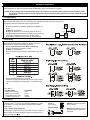
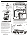
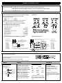
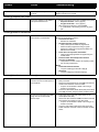
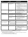
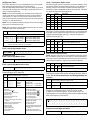
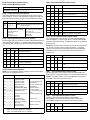
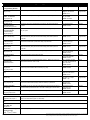
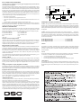
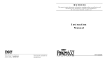
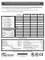
PC1616/PC1832/PC1864 STANDARD INSTALLATION GUIDE
This Installation Guide provides the basic installation, wiring and programming information required to program the PowerSeries PC1616,
PC1832 and PC1864 control panels. This guide shall be used in conjunction with the PowerSeries PC1616/1832/1864 Reference Manual
which can be obtained from your local dealer or downloaded from the DSC web site at www.dsc.com.
NOTE: All necessary information required to meet UL Listing requirements is contained in this document.
Read the complete guide, then work through each step as indicated.
FEATURES
OUT Of THE BOX
Qty 1
Qty 1
Qty 1
Qty 1
Qty 2
Qty 1
Qty 4
Qty 16
Qty 1
Qty 1
Qty 1
Qty 1
Cabinet
PC Module
Installation guide
User manual
Cabinet Label
Cabinet Door Plug
Standoffs
5.6KΩ Resistors
2.2KΩ Resistors
1.0KΩ Resistors
10Ω Resistors
Grounding Kit
PC1616
PC1832
PC1864
On-board Zones
6 (+2 keypad zones)
8
8
Hardwired Zones
16 (1xPC5108)
32(3xPC5108)
64 (7xPC5108)
Wireless Zones
16
32
32
On-board PGM Outputs
PGM 1 - 50mA
PGM 2 - 300mA
PGM 1 - 50mA
PGM 2 - 300mA
PGM 1, 3, 4 - 50mA
PGM 2 - 300mA
PGM Expansion
8x50mA (PC5208)
4x500 mA (PC5204)
8x50mA (PC5208)
4x500 mA (PC5204)
8x50mA (PC5208)
4x500 mA (PC5204)
Keypads
8
8
8
Partitions
2
4
8
User Codes
32 + Master Codes
32 + Master Codes
32 + Master Codes
Event Buffer
500 Events
500 Events
500 Events
Transformer Required
16.5VAC/40VA
16.5VAC/40VA
16.5VAC/40VA
Battery Required
4Ah / 7Ah/14AHr
4Ah / 7Ah/14AHr
4Ah / 7Ah/14AHr
Bell Output
12V/700 mA (cont)
12V/700 mA (cont)
12V/700 mA (cont)
Keypad Zone Support
SPECIFICATIONS
Temp Range........ 0°C-49°C (32°F-120°F)
Humidity (Max)........................... 93%R.H.
Power Supply ........16.5VAC/40VA @60Hz
Current Draw (Panel) .........110mA (nom.)
Aux+ Output ........... 11.1-12.6VDC/550mA
Bell Output ............. 11.1-12.6VDC/700mA
COMPATIBLE DEVICES
Keypads (Backward compatible with all PowerSeries keypads)
PK5500 Keypad ...........................................................150mA (max.)
PK5501 Keypad ...........................................................150mA (max.)
PK5508 LED Keypad ...................................................150mA (max.)
PK5516 LED Keypad ...................................................150mA (max.)
PC5532Z LED Keypad.................................................150mA (max.)
LCD5511Z Fixed Message LCD Keypad...................... 85mA (max.)
LED5511Z 8-zone LED Keypad ..................................100mA (max.)
Cabinets
PC5003C .....................................222x298x78mm (11.3x11.7x3.0in)
PC500C .........................................213x235x78mm (8.4x9.25x3.0in)
Modules
T-Link TL-250/TL300........................................................275/350mA
PC5100 2-wire Interface ............ 40mA plus devices to 170mA max.
PC5132-433 Wireless Receiver .............................................125mA
RF5108-433 Wireless Receiver .............................................125mA
PC5108 Zone Expander ...........................................................30mA
PC5204 Power Supply with 4 Programmable Outputs ............30mA
PC5208 Low Current Programmable Output Module ..............50mA
PC5400 Printer/DVAC Module .................................................65mA
PC5401 Bi-Directional RS232 Module (Not UL Listed) ............65mA
Escort5580 Telephone Interface Module ...............................130mA
Refer to the reference manual for additional devices.
Refer to the reference manual for alternate control cabinets
Classified in Accordance with ANSI/SIA CP-01-2000 (SIA-FAR)
2 9 0 0 7 1 0 9 R0 0 2
© February 2006, Digital Security Controls
Printed in Canada
Hardware Installation
Begin the installation by mounting the cabinet in a dry protected area with access to unswitched AC power.
Install Hardware in the sequence indicated below. Do NOT apply power until installation is complete.
NOTE: All wiring entry points are designated by arrows. All circuits are classified UL power limited except for the battery leads.
Minimum 1/4” (6.4mm) separation must be maintained at all points between power limited and non-power limited wiring and
connections.
1 KEYBUS Wiring
The 4-wire KEYBUS (red, black, yellow and green) is the communication connection between the control panel and all modules. The 4 KEYBUS terminals of all modules must be connected to the 4 KEYBUS terminals of the main control panel.
The following rules must be followed when wiring the Keybus:
•
•
•
•
Minimum 22 AWG wire, maximum 18 AWG (2-wire twisted preferred
Do NOT use shielded wire
Modules can be home run, connected in series or can be Ttapped provided that the maximum wire distance from the control
panel to any module does not exceed 1,000 feet (305m)
No more than 3,000 feet (915m) of wire can be used in total
B
150' (46.M)
150' (46.M)
Control
Panel
500' (152.M)
500' (152.M)
C
A
2 Zone Wiring
Zones can be wired for Normally Open, Normally Closed Contacts
with Single-end-of-line (SEOL) resistors or Double End-of-Line
(DEOL) resistors. Observe the following guidelines
•
For UL Listed Installations use SEOL or DEOL only.
•
Minimum 22 AWG wire, maximum 18 AWG
•
Do NOT use shielded wire
•
Wire run resistance shall not exceed 100Ω. Refer to the chart
below.
•
•
•
Section [001-004] Selects Zone Definition
Section [013] Opt [1] Selects Normally Closed or EOL resistors
Section [013] Opt [2] Selects Single EOL or Double EOL resistors.
Zone Status
Loop Resistance
- 0Ω (shorted wire/loop)
- 5600Ω (contact closed)
- infinite (broken wire, open)
- 11,200Ω (contact open)
Loop Status
Fault
Secure
Tamper
Violated
3 Bell Wiring
These terminals supply 700mA of current at 12VDC for commercial
installations and 11.1-12.6 VDC for residential installations (e.g.DSC
SD-15 WULF). To comply with NFPA 72 Temporal Three Pattern
requirements:
Program Section [013] Opt [8] ON.
The Bell output is supervised and power limited. If unused, connect a
1000Ω resistor across Bell+ and Bell- to prevent the panel from displaying a trouble. See [ ][2].
Bell/Siren
700mA (max)
NOTE: Bell output is current limited by 2A PTC
Observe Polarity.
Bell
NOTE: Steady, Pulsed and Temporal Three Pattern alarms are
supported.
Hardware Installation (Cont.)
North America Only
POWER LIMITED
1. Insert Stand off into cabinet
mounting hole in the
desired location. Snap-inplace.
PC Board
Stand Off
Cable Tie (not supplied) recommended
Cabinet
2. Position circuit board
mounting holes over
standoffs. Press firmly
on board to snap-in-place.
DSC
UA503
Primary:120VAC/60Hz.
Secondary: 16.5VDC 40VA
DSCPTD 1640U
Class II Transformer
PC1616/1832/1864
NOTE: Do not connect
transformer to receptacle
controlled by a switch
High Voltage. Disconnect AC Power
and telephone lines before servicing
WARNING:
PC1864
Only
PC1864
PC1832
Only
CON1
BAT+BAT-
TB-2
AC AC
AUX+
BELL+
PGM1
PGM3
AUXBELL- RED BLK YEL GRN
PGM2
PGM4 Z1 COM Z2
Z3 COM Z4
Z5 COM Z6
Z7 COM Z8 EGND
RING
TIP
R-1
T-1
230 VAC/50 Hz International
See Section 9
for ground wiring details
12V / 7 AHr
12V / 7 AHr
BLACK
RED
NON-POWER LIMITED
DSC Model BD7-12
or equivalent
Battery
Standby Time:
24Hrs min.
WARNING: Incorrect connections may result in PTC failure or improper operation.
Inspect wiring and ensure connections are correct before applying power.
Incorrect connection of batteries may result in battery rupture or Fire Hazard.
Do NOT allow metal objects to connect the Positive and Negative Terminals
Ensure that batteries are connected with correct polarity (Red to (+), Black to (-)).
Failure to comply with this may result in battery rupture and/or Fire Hazard.
All circuits are classified for UL Installations as power limited/Class II power limited
except for battery leads which are not power limited.
IMPORTANT:
1.This equipment, Alarm Controller PC1616/1832/1864 shall
be installed and used within an environment that provides the
pollution degree max 2 and overvoltages category II
NON HAZARDOUS LOCATIONS, indoor only. The equipment is
FIXED and PERMANENTLY CONNECTED and is designed to be
installed by service persons only; [service person is defined as a
person having the appropriate technical training and experience
necessary to be aware of hazards to which that person may be
exposed in performing a task and of measures to minimize the risks
to that person or other persons.]
Do NOT route any wiring over circuit boards. Maintain at least 1"(25.4mm) separation.
A minimum of 1/4" (6.4mm) separation must be maintained at all points between
power limited wiring and all other non-power limited wiring.
2.The connection to the mains supply must be made as per the local
authorities rules and regulations: In the UK as per BS6701.
An appropriate disconnect device must be provided as part of the
building installation. Where it is not possible to rely on identification of
the NEUTRAL in the AC MAINS SUPPLY, the disconnecting device
must disconnect both poles simultaneously (LINE and NEUTRAL).
The device shall disconnect the supply during servicing.
3.The equipment enclosure must be secured to the building structure
before operation.
4.Internal wiring must be routed in a manner that prevents:
- Excessive strain on wire and on terminal connections;
- Loosening of terminal; connections;
- Damage of conductor insulation
5.Disposal of the used batteries shall be made according to the waste
recovery and recycling regulations applicable to the intended market.
6. Before SERVICING, DISCONNECT the TELEPHONE CONNECTION.
WARNING:
High Voltage. Disconnect AC Power
and telephone lines before servicing
See corresponding Section NumberText for wiring details.
Hardware Installation (Cont.)
4 AUX Power Wiring
The control panel can provide a maximum of 550mA of current for modules, powered detectors, relays, LED’s etc.… If the total current
required exceeds 550mA an additional power supply is required (e.g.,PC5200, PC5204). See list below.
NOTE: Min/max operating voltages for devices, sensors and modules is 9.5VDC - 14VDC
Refer to the list of Compatible Devices on the first page for the current draw of individual devices
5 PGM Wiring
PGMs switch to ground when activated by control panel.
Connect the positive side of the device to be activated to the AUX+
Terminal. Connect the negative terminal to the PGM.
current output is as follows
•
PGM 1, 3, 4 .................... 50mA
•
PGM 2 .......................... 300mA
For currents levels greater than 300mA a relay is required.
PGM2 can also be used for 2-wire smoke detectors.
NOTE: Use SEOL resistors on Fire Zones ONLY.
PGM 1, LED Output with current limiting resistor and Optional Relay
driver output
AUX
AUX
1 PGM 2
1 PGM 2
BLK
RED
2-wire Smoke Detectors Initiating Circuit
•
•
•
•
•
•
•
•
•
WHT YEL
GRN
COM N.C. N.O.
Compatibility ID For FSA-210B Series is: FSA200
FSA-210B
FSA-210BT
FSA-210BS
FSA-210BST
FSA-210BLST
FSA-210BR
FSA-210BRT
FSA-210BRS
FSA-210BRST
FSA-210BLRST
4-wire Smoke Detectors
Smoke Detector must be latching type (e.g., DSC FSA 410B Series)
To reset smoke detector, Enter [✱] [7] [2]
NOTE:
Refer to Installation Manual and
Smoke Detector Instruction Sheet
when positioning detectors.
AUX
1 PGM 2
DSC
RM-1
Style B (Class B), Supervised, Power Limited
Compatibility Identifier ........................................................ PC18-1
DC Output Voltage..................................................... 9.8-13.8 VDC
Detector Load ............................................................. 2 mA (MAX)
Single-end-of-line (SEOL) Resistor ..................................... 2200Ω
Loop Resistance............................................................24Ω (MAX)
Standby Impedance.................................................. 1020Ω (ΝΟΜ)
Alarm Impedance ........................................................570Ω (MAX)
Alarm Current ............................................................ 89 mA (MAX)
Compatible 2-wire
Smoke Detector
DSC FSA-210B Series
AUX
1 PGM 2
AUX
RM-1 POWER LOOP
SUPERVISORY RELAY
35mA WHT
COM BLK
max.
1 PGM 2
Compatible 4-wire
Smoke Detector
DSC FSA-410B Series
IN
2200Ω
END-OF-LINE
RESISTOR
EOLR-3
SMOKE
DETECTOR
POWER
12 VDC
NO
ALM
IN
ALARM
INITIATING
LOOP
RESISTANCE
100Ω
OUT
OUT
NOTE: Do NOT combine models from different Manufacturers
On the same circuit. Operation may be impaired.
WHT
RED
GRN
FSA-410B
FSA-410BT
FSA-410BS
FSA-410BST
FSA-410BLST
FSA-410BR
FSA-410BRT
FSA-410BRS
FSA-410BRST
FSA-410BLRST
6 Telephone Line Wiring
Wire the telephone connection terminals (TIP, Ring, T-1, R-1) to an
RJ-31x Connector as indicated.
For connection of multiple devices to the telephone line, wire in the
sequence indicated.
Telephone format is programmed in section [350].
Telephone Call Directions are programmed in section [351]-[376].
7 Ground
8 Battery
Ground Installation
A sealed, rechargeable, lead
acid battery or gel type battery is
required to meet UL requirements for power standby times.
NOTE: UL Residential/Commercial Burglary installations require
4Hrs Power Standby time.
NOTE: UL/ULC Residential Fire
& Home Care installations
require 24 Hr power standby.
ULC Commercial Burglary
and Fire monitoring installations
require 24 Hr power standby.
Tighten nut to break paint
and make a good
connection to the cabinet
Nut
Lock washer
Nut
Lock washer
Star washer
Cabinet
Bolt
Earth ground
connection
Ground wire
from building
electrical
installation
9 AC Wiring
Standby Battery Guide
AC Wiring
Battery Charging Current: 400 mA
Batt
Standby
Size
4Hr
24Hr
------------------------------------------------4Ahr
550mA
---7Ahr
550mA
190mA
14Ahr
550mA
480mA
NOTE:
Replace batteries every 3-5 years.
Battery capacity will deteriorate with
age and number of charge/discharge
cycles
UL Listed Installations
Primary: 120VAC/60Hz./0.33A
Secondary: 16.5VAC/40VA
DSCPTD 1640 Plug-in, Class 2
Transformer.
NOTE: Do not connect transformer to a receptacle controlled
by a switch. (UL Listed Installations
Only)
TESTING & TROUBLESHOOTING
Testing:
•
•
Power up system
Program options as required (See Programming Section on reverse side)
Note: For advanced programming refer to the PC1616/1832/1864 Reference manual
•
•
Violate, then restore zones
Verify correct Reporting Codes are sent to the Central Station
Troubleshooting:
LCD5500 LCD Programmable-Message Keypad
•
•
•
Press [✱][2] to view a trouble condition.
The trouble light will flash and the LCD will display the first trouble condition present.
Use the arrow keys to scroll through all trouble conditions present.
NOTE: When additional information is available for a specific trouble condition a [✱] will appear on the display.
Press the [✱] key to view the additional information
LED Keypads, LCD Fixed Message Keypads
•
•
•
Press [✱][2] to view a trouble condition.
The trouble light will flash.
Refer to the Trouble Summary chart below to determine the trouble condition(s) present.
Trouble Summary:
Light [1]✱ Service Required - Press [1] for more information
[1] Low Battery
[2] Bell Circuit
[3] General System Trouble
[4] General system Tamper
[5] Module Supervision
[6] RF Jam Detected
[7] PC5204 Low Battery
[8] PC5204 AC Failure
Light [2] AC Trouble
Light [3] Telephone Line Trouble
Light [4] Failure to Communicate
Light [5]✱ Zone Fault -Press [5] for more information
Light [6]✱ Zone Tamper - Press [6] for more information
Light [7]✱ Wireless Device Low Battery - Press [7] for more information
Light [8] Loss of Time or Date
Trouble
Cause
Trouble [1] Service Required
Press [1] to determine specific trouble
[1] Low Battery
Main panel battery less than 11 VDC
NOTE: This trouble condition will not
clear until the battery voltage is
12.5VDC min., under load.
[2] Bell Circuit
Bell+, Bell-...Open Circuit
Troubleshooting
NOTE: If battery is new allow 1 Hr. for battery to charge.
•
Verify voltage measured across AC terminals is
16-18 VAC. Replace transformer if required.
•
Disconnect battery wire leads
• Verify battery charging voltage measured across battery leads = 13.70 - 13.80 VDC.
•
Connect battery, remove AC power
• Verify measured voltage across battery terminals is
12.5VDC min.
•
•
[3] General System Trouble
PC5204 Output#1 Open Circuit
•
•
PC5204 AUX
•
•
[4] General System Tamper
[5] Module Supervision
Disconnect Bell-/Bell+ wire leads, measure resistance
of wire leads.
• Open circuit indicates break in wiring or defective
siren/bell
Jumper Bell+, Bell- with 1K resistor (Brown, Black, Red)
• Verify trouble clears
If Output#1 is unused: Ensure that terminals O1, AUX
are jumpered with 1K resistor (Brown, Black, Red)
If Output #1 is used: Disconnect wire leads from O1,
AUX terminals, measure the resistance of the wire leads
• Open circuit indicates a break in the wiring
Verify voltage measured across AC input terminals is
16-18VAC.
Disconnect all connections to PC5204 AUX terminal.
• Verify AUX voltage is 13.70 - 13.80 VDC.
Printer connected to PC5400 offline
Verify printer operation (out of paper, paper jam etc.)
T-Link Network Fault present
T-Link Receiver Trouble present
T-Link Interface Trouble present
Refer to the T-Link TL250/350 Installation Manual for details.
Tamper input on module(s) open
circuit
Short tamper terminal to COM terminal on unused modules
connected to KEYBUS (PC5100, PC5108, PC5200,
PC5204, PC5208, PC5320, PC5400, PC5700).
Wireless Receiver - excessive noise
detected
Check for external 433MHZ signal sources
To disable RF Jam: enable Option [7] in program section
[804] subsection [90].
Panel does not communicate with
module(s) on KEYBUS
Modules are immediately enrolled and supervised when
detected on the KEYBUS. If a module has been removed, or
if the slot assignment of a keypad has been changed, module supervision must be reset.
•
View the event buffer (via DLS or LCD5500 keypad) to
identify the specific module(s) in trouble
•
To reset module supervision:
• Enter Program Section [902].
• Press [#] (wait 1 minute for panel to scan KEYBUS).
•
Enter Program Section [903] to identify modules
connected to KEYBUS.
Keypad assigned to incorrect slot.
[6] RF Jam Detected
Wireless Receiver - excessive noise
detected.
Check for external 433MHZ signal sources
To disable RF Jam: enable Option [7] in program section
[804] subsection [90].
[7] PC5204 Low Battery
PC5204 battery less than 11.5VDC
See [1] Low Battery above
NOTE: This trouble condition will not
clear until the battery voltage is
12.5VDC min., under load.
[8] PC5204 AC Failure
No AC at PC5204 AC inputs
Verify voltage measured across AC terminals is 16-18VAC.
Replace transformer if required.
Trouble
Cause
Troubleshooting
No AC at panel AC input
terminals
Verify voltage measured across AC terminals is 16-18VAC.
Replace transformer if required.
Phone Line Voltage at TIP, RING on
main panel less than 3VDC
•
Trouble [2] AC Failure
Trouble [3] Telephone Line Trouble
•
Measure the voltage across TIP and RING on the panel:
• No phone off-hook – 50VDC (approx)
• Any phone off-hook – 5VDC (approx)
Wire incoming line directly to TIP and RING.
• If trouble clears, check wiring or the RJ-31 phone
jack.
Trouble [4] Failure to Communicate
Panel fails to communicate one or
more events to central station
Trouble [5] Zone Fault
Connect a headset to TIP and RING of the control panel.
Monitor for the following conditions:
•
Continuous dial tone
• Reverse TIP and RING
•
Recorded operator message comes on
• Verify correct phone number is programmed
• Dial the number programmed using a regular
telephone to determine if a [9] must be dialed or if
800 service is blocked.
•
Panel does not respond to handshakes.
• Verify the format programmed is supported by the
central station.
•
Panel transmits data multiple times without
receiving a handshake
• Verify that the account number and reporting codes
are correctly programmed.
NOTE:
Contact ID and Pulse formats
• Program a HEX [A] to transmit a digit [0]
SIA format
• Program a digit [0] to transmit a digit [0]
Press [5] to determine specific zones with a fault trouble
Open circuit is present on one or
more fire zones on the main panel or
zone expander
•
•
•
An open circuit is present on PGM2
being used as a 2-wire smoke
detector input
•
•
•
Ensure fire zones have a 5.6K resistor (Green, Blue,
Red) connected.
Remove the wire leads from Z and COM terminals and
measure the resistance of the wire leads.
• An open circuit indicates a break in the wiring or
resistor not connected.
Connect a 5.6K resistor (Green, Blue, Red) across the Z
and COM terminals. Verify the trouble condition clears.
Ensure the correct 2.2K end-of-line resistor is connected (Red, Red, Red).
Remove the wire leads from PGM2 and AUX+ terminals
and measure the resistance of the wire leads.
• An open circuit indicates a break in the wiring or no
resistor connected.
Connect a 2.2K resistor (Red, Red, Red) across the
PGM2 and AUX+ terminals. Verify the trouble condition
clears.
Trouble
Cause
Troubleshooting
One or more wireless devices have
not checked in within the
programmed time
•
Trouble [5] Zone Fault (Cont.)
•
A short circuit is present on one or
more zones with double end-of-line
resistors enabled
•
•
Trouble [6] Zone Tamper
If the trouble occurs immediately, a conflict with a hard
wired zone exists:
• The zone being used is already assigned to a
PC5108 zone expander
• The zone being used is assigned as a keypad zone
Perform a Module Placement Test – Program Section
[904] and verify the wireless device is in a good location.
• If bad test results occur, test the wireless device in
another location
• If the wireless device now tests good, the original
mounting location is bad
• If the wireless device continues to give bad test
results replace the wireless device
Remove the wire leads from Z and COM terminals and
measure the resistance of the wire leads.
• A short circuit indicates a short in the wiring.
Connect a 5.6K resistor (Green, Blue, Red) across the Z
and COM terminals.
• Verify the trouble condition clears.
Press [6] to determine specific zones with a tamper trouble
A tamper condition is present on one
or more wireless devices
•
•
Perform a Module Placement Test –Section [904]
Violate, then restore the tamper:
• If no test result then replace wireless device
An open circuit is present on one or
more zones with double end-of-line
resistors enabled
•
•
Remove the wire leads from Z and COM terminals.
Measure the resistance of the wire leads.
• Open circuit indicates a break in the wiring.
Connect a 5.6K resistor (Green, Blue, Red) across the Z
and COM terminals.
• Verify the trouble condition clears.
•
Trouble [7] Wireless Device Low Battery
Press [7] to toggle through specific devices with low battery trouble
1st press – Wireless Zones
One or more wireless devices has a
low battery
Replace battery
2nd press – Handheld Keypads
NOTE: The event will not be logged
to the event buffer until the wireless
device low battery delay time expires
• Program Section [377] Opt 9
NOTE: Replacing batteries will cause a tamper. Replacing
cover will restore the tamper causing the associated reporting codes to be sent to the Central Station.
The main panel internal clock is not
set
To program the time and date:
•
Enter [✱][6][Master Code] then Press [1]
or Press function key programmed with definition #26
•
Enter the time and date (in military) using the following
format: HH:MM MM/DD/YY
Example.
For 6:00 pm, June 29, 2005
Enter: [18] [00] [06] [29] [05]
3rd press – Wireless Keys
Trouble [8] Loss of Clock/Date
IMPORTANT!
Ensure you have the following information available before contacting Customer Support
- Control Panel Type and Version, (e.g., PC1864 v4.1)
NOTE: Version number can be accessed by entering [✱][Installer Code][900] on any system keypad. This information is
also located on a sticker on the Printed Circuit Board.
- List of modules connected to Control Panel, (e.g., PC5400, PC5204 etc.)
PROGRAMMING
How to Program:
DSC recommends filling in the Programming Worksheet with the required
programming information before programming the system. This will reduce the
time required to program and will help eliminate errors.
To enter Installer Programming press [*][8][5555].
The Program light will FLASH (or in the case of the programmable LCD keypad
the display will change to ‘Enter Section’).
An error tone indicates the installer code entered is not correct.
Press [#] to clear any key presses and try again.
the required data. The Ready light will turn OFF and the Armed light
will turn ON.
At any time the [#] can be pressed to exit any program section. All
changes made up to that point will be saved.
HEX (or hexadecimal) digits are sometimes required. To enter a HEX
digit, press the [*] key to begin HEX programming. The Ready light will
FLASH. Refer to the chart below and press the number corresponding
to the HEX digit required. The Ready light will continue to FLASH.
Press [*] again to return to normal decimal programming. The Ready
light will turn ON.
HEX [A]
HEX [B]
HEX [C]
HEX [D]
HEX [E]
HEX [F]
The Armed and Ready lights indicate programming status:
Armed Light ON
Ready Light ON
Ready Light FLASHING
NOTE:
Panel waiting for 3-digit section number
Panel waiting for data to be entered
Panel waiting for HEX data to be entered
You cannot enter installer programming while the system is armed or
in alarm.
Enter the 3-digit programming section number.
•
The Armed light will turn OFF and
•
The Ready light will turn ON.
•
The keypad will display which toggle options are ON or OFF according to
the chart below:
•
•
How to Exit Installer Programming:
To exit installer programming, press the [#] key when the panel is
waiting for a 3-digit section number (the Armed light is ON).
Programming Toggle Options:
•
[*] [1] [*]
[*] [2] [*]
[*] [3] [*]
[*] [4] [*]
[*] [5] [*]
[*] [6] [*]
Keypad Type
Option ON
Option OFF
LED
Zone Light ON
Zone Light OFF
Fixed-Message LCD
Indicator # ON
Indicator # OFF
Programmable-Message LCD
# Displayed
Dash [-] Displayed
Viewing Programming
LED and LCD5501Z Keypads
Any programming section can be viewed from an LED or LCD5501Z keypad. When a programming section is entered, the keypad will immediately
display the first digit of information programmed in that section.
The keypad displays the information using a binary format, according to
the following chart:
See Hex data
entry instructions
To toggle an option ON or OFF, press the corresponding number on the
keypad. The display will change accordingly.
When all the toggle options are configured correctly, press the [#] key to
exit the program section.
The Ready light will turn OFF and the Armed light will turn ON.
NOTE:
If the panel is a local system, press [#] to skip this step.
NOTE:
In addition to the standard digits 0-9, HEX digits can also be
programmed if required.
Press any of the Emergency keys (Fire, Auxiliary or Panic) to advance to
the next digit.
When all the digits in a section have been viewed, the panel will exit the
section: the Ready light will turn OFF, and the Armed light will turn ON,
waiting for the next three-digit programming section number to be
entered.
Press the [#] key to exit the section
LCD Keypad
HEX [A]
HEX [B]
HEX [C]
HEX [D]
HEX [E]
Not Supported
Simulated [*] key
Simulated [#] key
Dial tone search
Two second pause
Press
Press
Press
Press
When a programming section is entered, the keypad will immediately display all the information programmed in that section. Use the arrow keys (<
>) to scroll through the data being displayed. To exit the section, scroll
past the end of the data displayed, or press the [#] key.
[*][2][*]
[*][3][*]
[*][4][*]
[*][5][*]
DLS Programming
Programming Decimal and Hexadecimal (HEX) Data:
•
•
•
Enter the 3-digit programming section number.
The Armed light will turn OFF and The Ready light will turn ON.
Enter the data written in the boxes.
For sections that require multiple 2 or 3 digit numbers, the keypad will
double-beep after each 2 or 3 digit entry and move to the next item in
the list. After the last digit in the section is entered, the keypad will
beep rapidly 5 times and exit the program section. The Ready light will
turn OFF and the Armed light will turn ON.
For sections that do not require data for every box (such as phone
numbers) press the [#] key to exit the program section after entering all
Hardware Setup - Local (PC-Link)
Connect a RS-232 to PC-Link Cable between the Computer with DLS
Software installed and the alarm panel to be programmed.
[401] First Downloading Option Code
The 1st toggle option in this section is used to enabled/disable Downloading.
Configure the options as required and press [#] to exit.
Opt
2
Default
I__I
Description
ON
User can enable DLS Window
OFF
User can NOT enable DLS Window
[402] Downloading Computer Phone Number (32-digits)
I
DII___II___II___II___II___II___II___II___II___II___II___II___II___II___II___I
I___II___II___II___II___II___II___II___II___II___II___II___II___II___II___II___I
[403] Downloading Access Code
Enter 4 or 6-digit code
This code identifies the downloading computer to the panel.
The downloading access code prevents unauthorized access to the panel.
This code must match the code programmed in the downloading file before the
panel will allow remote or local DLS connection. Enter a new downloading
access code to disable downloading.
Default XXXXXX
I___II___II___II___II___II___I
[404] Panel Identification Code
This code identifies the panel to the downloading computer.
See section [403]
Null Key (Key not used)
Partition 1 Select
Partition 2 Select
Stay Arm
Away Arm
[ ][9] No entry arm
[ ][4] Chime On/Off
[ ][6][----][4]System Test
[ ][1] Bypass Mode
[ ][2] Trouble display
[ ][3] Alarm memory
[ ][5] User programming
[ ][6] User functions
Command output 1 [ 71]
Command output 1 [ 72] Sensor
Reset
15 General voice prompted help
16 [ ][0] Quick Exit
17 [ ][0] Activate Stay/Away
18 Identified voice prompted
help
19 Command output 3 [ 73]
20 Not used
21 Command output 4 [ 74]
22 Active camera monitor
selection
23 Bypass Recall
24 Bypass Group Recall
25 Not Used
26 Time Programming
27 Partition 3 Select
28 Partition 4 Select
29 Partition 5 Select
30 Partition 6 Select
31 Partition 7 Select
32 Partition 8 Select
Enter the number corresponding to the zone definitions required.The keypad
will beep rapidly 3 times and move to the next step. If an invalid number is
entered the keypad will revert to the default setting (option [1]).
I___II___II___II___II___II___I
Press [#] to exit the section.
[499][Installer Code][499] Initiate PC-Link
Enter [499][Installer Code][499]
[001] Zone 1-16 Definitions ALL Models
Special Installer Functions
Enter section# for the following features
[900]
[902]
[903]
[904]
00
01
02
03
04
05
06
07
08
09
10
11
12
13
14
[001]-[004] Zone Definitions
Enter 6 decimal places
Default XXXXXX
KEYPAD FUNCTION KEY DEFINITIONS
Panel Version ([ ][8][Installer Code][900])
Module Supervision Reset ([ ][8][Installer Code][902])
Module Supervision Field ([ ][8][Installer Code][903])
Wireless Module Placement Test ([ ][8][Installer Code][904])
Enter section#, Installer Code section# for the following features
Def
Def
01 I__II__I Zone 1
03 I__II__I Zone 2
03 I__II__I Zone 3
03 I__II__I Zone 4
04 I__II__I Zone 5
04 I__II__I Zone 6
04 I__II__I Zone 7
04 I__II__I Zone 8
00 I__II__I Zone 9
00 I__II__I Zone 10
00 I__II__I Zone 11
00 I__II__I Zone 12
00 I__II__I Zone 13
00 I__II__I Zone 14
00 I__II__I Zone 15
00 I__II__I Zone 16
[002] Zone 17-32 Definitions PC1864 & PC1832
[990] INSTALLER CODE [990]
[991] INSTALLER CODE [991]
[993] INSTALLER CODE [993]
[995] INSTALLER CODE [995]
[996] INSTALLER CODE [996]
[997] INSTALLER CODE [997]
[999] INSTALLER CODE [999]
Installer Lockout Enable
Installer Lockout Disable
Restore Alt.Comm. Factory Defaults
Restore Escort 5580 Factory Defaults
Restore PC5132 Factory Defaults
Restore PC5400 Factory Defaults
Restore Panel Factory Defaults
[000] Keypad Programming
Note: This programming must be done at each keypad
[0]
[1]
[2]
[3]
[4]
[5]
LCD5501Z
LED
Defaults
11
LCD5500Z
Defaults
18
Keypad 1
Keypad 2
Keypad 3
Keypad 4
Keypad 5
Keypad 6
Keypad 7
Keypad 8
Def
00 I__II__I Zone 17
00 I__II__I Zone 18
00 I__II__I Zone 19
00 I__II__I Zone 20
00 I__II__I Zone 21
00 I__II__I Zone 22
00 I__II__I Zone 23
00 I__II__I Zone 24
00 I__II__I Zone 25
00 I__II__I Zone 26
00 I__II__I Zone 27
00 I__II__I Zone 28
00 I__II__I Zone 29
00 I__II__I Zone 30
00 I__II__I Zone 31
00 I__II__I Zone 32
[003] Zone 33-48 Definitions PC1864 Only
Slot Address (0-8) for partition, 1-8 for slot
Function key Assignment (00-32)
Function key Assignment (00-32)
Function key Assignment (00-32)
Function key Assignment (00-32)
Function key Assignment (00-32)
Slot Address
Def
Key
1
Key
2
Key
3
Key
4
Key
5
03
04
06
14
16
Def
Def
00 I__II__I Zone 33
00 I__II__I Zone 34
00 I__II__I Zone 35
00 I__II__I Zone 36
00 I__II__I Zone 37
00 I__II__I Zone 38
00 I__II__I Zone 39
00 I__II__I Zone 40
00 I__II__I Zone 41
00 I__II__I Zone 42
00 I__II__I Zone 43
00 I__II__I Zone 44
00 I__II__I Zone 45
00 I__II__I Zone 46
00 I__II__I Zone 47
00 I__II__I Zone 48
[004] Zone 49-64 Definitions PC1864 Only
03
04
06
14
16
Def
Def
00 I__II__I Zone 49
00 I__II__I Zone 50
00 I__II__I Zone 51
00 I__II__I Zone 52
00 I__II__I Zone 53
00 I__II__I Zone 54
00 I__II__I Zone 55
00 I__II__I Zone 56
00 I__II__I Zone 57
00 I__II__I Zone 58
00 I__II__I Zone 59
00 I__II__I Zone 60
00 I__II__I Zone 61
00 I__II__I Zone 62
00 I__II__I Zone 63
00 I__II__I Zone 64
00 Null Zone (not used)
01 Delay 1
02 Delay 2
03 Instant
04 Interior
05 Interior, Stay/Away
06 Delay, Stay/Away
07 Delayed 24-hr Fire
(Hard-wired)
08 Standard 24-hr Fire
(Hard-wired)
09 24-hr Supervisory
10 24-hr Supervisory Bu
11 24-hr Burglary
12 24-hr Holdup
13 24-hr Gas
14 24-hr Heat
15 24-hr Medical
16 24-hr Panic
17 24-hr Emergency
18 24-hr Sprinkler
19 24-hr Water
20 24-hr Freeze
21 24-hr Latching
Tamper
22 Momentary Keyswitch
arm
23 Maintained Keyswitch Arm
24 Future Use
25 Interior Delay
26 25-hr non-alarm
27 Delayed 24-hr Water
Flow
28 Instant 24-hr Water
Flow
29 Auto-verified Fire
30 Fire Supervisory
31 Day zone
32 24-hr Bell/Buzzer
33 Push to set
34 Final Door set
35 Instant Stay, Away
36 24-hr Non latching
Tamper
37 Night Zone
87 Delayed 24-hr Fire
(Wireless)
88 24-hr Fire (Wireless)
[013] – First System Option Code
[005] System Times
This section programs the entry and exit delays for the control panel.
After entering section [005] press [1] to select partition 1.
Enter the 3-digit delay time for Delay 1 type zones, Delay 2 type zones
followed by the exit delay time. Press [#] to exit the sub-menu and
return to regular programming.
NOTE: For SIA FAR Installations, the Exit Delay must be within the
range of 045-255 seconds (Default 60 seconds). If the Exit Delay is
silent (Section 14, Option 6 or Stay Function Key Arming) the exit
delay must be twice the programmed value but must not exceed 255
seconds (i.e., 090-255 seconds).
The first two toggle options in this section are used to determine what
type of EOL resistors are being used, toggle option [1] to determine if
normally-closed or EOL resistors are being used and option [2] to
determine if single or double EOL resistors are being used. Configure
the options as required and press [#] to exit.
Opt
NOTE: For UL Installations, the Entry Delay plus the Communications
Delay must not exceed 60 seconds.
NOTE: Exit Time Restart shall be disabled when the panel is used in
combination with T-Link TL250/TL300.
[005]
[01] Partition 1 Entry/Exit Times
Def
Enter 3 digits [[001]-[255]
030 I___II___II___I
*045 I___II___II___I
**120 I___II___II___I
Entry Delay 1
Entry Delay 2
Exit Delay 1
Valid entries: [030] to [255]
Valid entries: [030] to [255]
Valid entries: [060] to [255]
I__I
2
I__I
8
I__I
Opt
2
7
I___II___II___II___II___II___I
[007] Master Code
Enter a new 6-digit Master Code
I___II___II___II___II___II___I
[008] Maintenance Code
Enter a new 6-digit Maintenance Code
Main Board PGM Output Programming
Def
19
10
01
01
Enter 2 digits [[01]-[32]
I___II___I
I___II___I
I___II___I
I___II___I
OFF
End-of-line Resistors
ON
Double End-of-Line Resistors
OFF
Single End-of-Line Resistors
ON
Temporal Three Fire Signal
OFF
Standard Pulsed Fire Signal.
Default
I__I
I__I
Description
ON
[P] Key Audible (Bell/Beeps) loops
OFF
[P] Key Silent
ON
TLM Enabled
OFF
TLM Disabled
NOTE: The panel uses the cross zoning attribute for Burglary Verification. This feature requires two or more trips on a zone(s) specified as
‘cross zones’ within a specified time before starting an alarm sequence
(See Section[101] Option 3, page 33 of the Reference Manual).
Opt
Default
I__I
Description
ON
Cross Zoning Enabled
OFF
Police Code is Enabled
I___II___II___II___II___II___I
[009-010] PGM Programming
PGMs 3&4 apply to PC1864 only
[009]
Normally Closed loops
[018] Cross Zone/Police Code
6
Default AAAAAA
ON
[015] – Third System Option Code
[006] Installer Code
Enter a new 6-digit Installer Code
Default 123456
1
Description
This section is used to determine if the Panic keys on the keypads will
be audible or silent (toggle option [2]) and if phone line supervision is
enabled or disabled (toggle option [7]). Configure the options as
required and press [#] to exit.
*Entry Delay 2 Default is 030 for SIA CP-01 Installations
**Exit Delay 1 Default is 060 for SIA CP-01 Installations
Default 555555
Default
PGM 1
PGM 2
PGM 3
PGM 4
01 Fire & Burglary Output
02 Not Used
03 Sensor Reset ( 72)
04 2-Wire Smoke (PGM2 Only)
05 Armed Status)
06 Ready to Arm
07 Keypad buzzer follow mode
08 Courtesy Pulse
09 System Trouble output (with Trouble
Options)
10 System Event (with Event Options)
11 System Tamper (All Sources)
12 TLM and Alarm
13 Kiss-off Output
14 Ground Start Pulse
15 Remote Operation
16 Future Use
Section [009]
Section [009]
Section [010] ...... PC1864 Only
Section [010] ...... PC1864 Only
17 Away Armed Status
18 Stay Armed Status
19 Command Output#1 ( 71)
20 Command Output#1 ( 72)
21 Command Output#1 ( 73)
22 Command Output#1 ( 74)
23 24-hr Silent Input
24 24-hr Audible Alarm
25 Delayed Fire & Burglary Output
26 Battery Test Output
27 Police Code Output
28 Holdup Output
29 Zone Follower Inverted Output
30Partition Status Alarm Memory
Output
31 Alternate Communications
32 Open After Alarm (Abort Code)
[165] Maximum Dialing Attempts to each Phone Number
This section programs the number of Dialing Attempts. Enter a
3-digit. For UL Listed Installations 5-10 Dialing attempts are
required.
[165]
Maximum Dialing Attempts to each Phone
Def
005
Enter 3 digits [[001]-[005]
I___II___II___I
Valid entries: [001] to [005]
[301] First Telephone Number (32-digits)
Program the central station phone number or CAA for T-LINK.
In addition to the standard digits [0] - [9], Hex digits may also be
required (Refer to the “Programming Decimal and Hexadecimal (HEX)
Data” at the beginning of this section).
I
DII___II___II___II___II___II___II___II___II___II___II___II___II___II___II___I
I___II___II___II___II___II___II___II___II___II___II___II___II___II___II___II___
[304] Call Waiting Cancel String (6 Digits)
Program Unused digits with Hex F
Default DB70EF [Hex]
I___II___II___II___II___II___I
[310]-[311] Partition Identifier Codes
Enter a 6 digit Maintenance Code
[380] – First Communicator Option Codes
Opt
[310 System Acct. Code
I___II___II___II___II___II___I
[311] Partition 1 Acct. Code
I___II___II___II___I
1
[350] – Communicator Format Options
This section determines the communication format used for central
station reporting. From the chart listed below program the 2-digit number for the desired format for the first and second telephone number
Def
04
04
3
I__I
I__I
I__I
Enter 2 digits From Chart Below
I___II___I
I___II___I
NOTE: 3rd Phone Number follows the format of the
1st Phone Number
01 20BPS, 1400 Hz Handshake
02 20BPS, 2300 Hz Handshake
03 DTMF Contact ID
04 SIA FSK
05 Pager
06 Residential Dial
07 10BPS, 1400 Hz Handshake
08 10BPS, 2300 Hz Handshake
09 Private Line
10 Scantronics 4-8-1 Fast Slo
12 Robofon
13 CESA 200
[367] – Opening/Closing Call Direction Options
The first toggle option in this section is used to enable/disable opening/
closing reporting for partition 1. To enable opening/closing reporting
turn option [1] ON. Configure the options as required and press [#] to
exit
.
Opt
1
2
Default
Default
I__I
Description
ON
1st Telephone Number
OFF
Disabled
ON
2nd Telephone Number
OFF
Disabled
ON
Alternate Communicator
OFF
Disabled
5
8
I__I
I__I
I__I
I__I
Communications Enabled
OFF
Communications Disabled
ON
Restorals on Bell Time-out
OFF
Restorals Follow Zones
ON
Pulse Dialing
OFF
DTMF Dialing
ON
3rd Telephone Number Enabled
OFF
3rd Telephone Number Disabled
ON
Delinquency Follows Zone Activity (Hours)
OFF
Delinquency Follows Arming (Days)
The 3rd toggle option in this section is used to enable/disable automatic SIA reporting. The 5th toggle option is used to enable/disable
automatic Contact ID reporting. Configure the options as required and
press [#] to exit.
NOTE:If the automatic SIA or automatic Contact ID reporting formats
are not used, reporting codes must be programmed. To program
reporting codes refer to the PowerSeries PC1616/1832/1864 Reference Manual which can be downloaded from the DSC web site at
www.dsc.com
3
5
ON
[381] – Second Communicator Option Codes
Opt
2
Description
5
Default
I__I
I__I
Description
ON
SIA Sends Programmed Reporting Codes
OFF
SIA Sends Automatic Reporting Codes
ON
Contact ID Uses Programmed Reporting
Codes
OFF
Contact ID Uses Automatic Reporting Codes
[377] Communication Variables
NOTE: For UL Installations, the Entry Delay plus the Communications
Delay must not exceed 60 seconds.
Def
Enter 3 digits as indicated below
003 I___II___II___I
Swinger Shutdown
(Alarms and Rest.
Swinger Shutdown
(Tamper and Rest.
Swinger Shutdown
(Maint. and Rest.
Communication Delay
AC Failure Comm Delay
TLM Trouble Delay
003 I___II___II___I
003 I___II___II___I
000 I___II___II___I
030 I___II___II___I
010 I___II___II___I
030 I___II___II___I
030 I___II___II___I
007 I___II___II___I
030 I___II___II___I
000 I___II___II___I
Test Transmission Cycle
(land line)
Not Used
Zone low Battery
Transmission Delay
Delinquency Transmission Cycle
Communications
Cancelled Window
(001-014 Transmissions)
(001-014 Transmissions,
000=disabled)
(001-014 Transmissions,
000=disabled)
(000-255 seconds)
(001-255 minutes)
No. of checks req’d (003255)
(001-255 days/minutes)
[382] – Third Communicator Option Codes
The 4th toggle option in this section is used to enable/disable Call
Waiting Cancel. Configure the options as required and press [#] to exit.
NOTE:A Call Waiting Cancel on a Non Call Waiting line will prevent
successful connection to the central station.
Opt
4
5
Default
I__I
I__I
Description
ON
Call Waiting Cancel Enabled
OFF
Call Waiting Cancel Disabled
ON
T-Link Interface Enabled
OFF
T-Link Interface Disabled
[701] – First International Options Codes
(000-255 days)
(000-255 days/hours)
(000-255 minutes)
NOTE: Option 1 is defaulted to 001 for CP-01 Installations
Option 4 is defaulted to 030 for CP-01 Installations
Option 11 is defaulted to 005 for CP-01 Installations
Option 7 in this section Selects Battery Charge Options.
Select ON for 7 Ahr and 14 Ahr batteries (700 mA charge rate)
Select OFF for Standard 4 Ahr batteries (400 mA charge rate)
Opt
7
Default
I__I
Description
ON
High Current Battery Charge (700mA)
OFF
Standard Battery Charge Rate (400mA)
LISTING REQUIREMENTS
UL Listed Commercial and Residential Installations
The installation requirements listed below must
be met for the following grades of service.
Grade AA Central Station and Police Connect
The installation must use T-Link module which communicates over LAN/WAN to
the Sur-Gard MLR-IP receiver. Polling time must be 90 seconds. Compromise
detection time must be 6 minutes.
Grade A Local
•The installation must have a bell which is UL Listed for mercantile local alarms
(AMSECO MBL10B with model AB-12 bell housing).
•The digital communicator must be enabled.
•The control panel must be in the attack-resistant enclosure (DSC Model CMC-1
or PC4050CAR).
Grade B Central Station and Police Connect
•The installation must have a bell which is UL Listed for mercantile local alarms
(AMSECO MBL10B with model AB-12 bell housing).
•The digital communicator must be enabled.
•The control panel must be in the attack resistant enclosure (DSC Model CMC-1
or PC4050CAR).
Grade C Central Station
•The digital communicator must be enabled.
•The control panel must be in the attack resistant enclosure (DSC Model CMC-1
or PC4050CAR).
All Commercial Installations
•The Entry Delay must not exceed 120 seconds
•The Exit Delay must not exceed 120 seconds.
•The minimum Bell Time-out is 15 minutes.
Residential Fire & Burglary Installations
•The Entry Delay must not exceed 45 seconds
•The Exit Delay must not exceed 60 seconds.
•The minimum Bell Time-out is 4 minutes.
Home Health Care Signaling Equipment
•There must be at least two keypads, one of either the LCD5500Z/LCD5520Z or
LCD5501Z and one of the following models, PC5508Z, PC5516Z or PC5532Z.
•Each system shall be programmed to activate an audible Trouble signal within 90
seconds upon loss of microprocessor memory.
•The minimum Bell Time-out is 5 minutes.
Programming
The notes in the programming sections describing the system configurations for
UL Listed installations must be implemented.
Control of the Protected Premises
In order to have a UL Certificated system the protected area is to be under the
responsibility of one ownership and management (i.e., one business under one
name). This may be a group of buildings attached or unattached with different
addresses but under the responsibility of someone having mutual interest. The
person of mutual interest is not the alarm-installing company.
Bell Location
The alarm sounding device (bell) must be located where it can be heard by the
person or persons responsible for maintaining the security system during the daily
arming cycle.
Protection of the Control Unit
The local control and the local power supply must be protected in one of the following ways:
•The control unit and audible alarm device must be in a protected area which is
armed 24 hours a day.
•Each partition must arm the area protecting the control unit and the audible
alarm device power supply. This may require duplicate protection armed by each
partition. Access to this protected area, without causing an alarm, will require
that all partitions be disarmed.
•In all cases described above, the protected area for the control unit must be programmed as not-bypassable.
Casual Users
The installer should caution the user(s) not to give system information to casual
users (e.g. codes, bypass methods, etc. to baby-sitters or service people). Only the
One-Time Use codes should be given to casual users.
User Information
The installer should advise the users and note in the User’s Manual:
•Service organization name and telephone number
•The programmed exit time
•The programmed entry time
•Test system weekly
Two-Wire Smoke Detector Compatibility (if available)
Maximum loop resistance: 24 Ohms (if available)
•Operating Voltage Range: 8.9 - 13.4 (if available)
•Maximum Alarm Current: 89 mA (if available)
•Compatibility Identifier: PC18-1
See Section 5 PGM Wiring for compatible 2-wire smoke detectors.
SIA FAR Installations
Minimum requirement system for SIA-FAR Installations:
• 1 PC1864/1832/1616 Control panel
• 2 Local annunciation devices
The local annunciation devices may be any combination of the following keypads.
• LCD5500Z
• LCD5501Z
• PK5500
• PKP-LCD
• PKP-ICN
• PK5501
The following optional subassembly modules also bear the SIA FAR classification
and may be used if desired:
PC5108 Zone Expander Module
Compatible initiating devices: Bravo200 series, 300 series, 400 series, 500 series,
600 series, AC-100, Encore300 series, Force200 series, 210 series, MN240.
PC5208 Low Current PGM Output Module
The following optional accessory modules also bear the SIA FAR classification and
may be used if desired.
PC5204 Auxiliary Power Supply with PGM output ports
Escort5580/Escort5580TC, PC5400 Printer Module
Caution
• For SIA FAR installations, only use modules / devices that are listed on this page.
• Fire Alarm Verification feature (Auto Verified Fire zone) is not supported on 2wire smoke detectors zones. This feature may be enabled for 4-wire smoke
detectors only.
• Call Waiting Cancel (Section 382 Option 4) feature on a non-Call Waiting line
will prevent successful communication to the central station.
• All smoke detectors on the system must be tested annually by conducting the
Installer Walk Test prior to exiting the walk test mode, a sensor reset must be
conducted on the system, [ ][7][2] to reset all latching 4-wire smoke detectors.
Please refer to the smoke detector installation instructions on how to correctly
test the detectors.
Notes
• Programming at installation may be subordinate to other UL requirements for
the intended application.
• Cross zones have the ability to individually protect the intended area (e.g.,
motion detectors, which overlap).
• Cross zoning is not recommended for line security Installations nor is it to be
implemented on exit / entry zones.
• There is a communication delay of 30 seconds in this control panel. It can be
removed, or it can be increased up to 45 seconds at the option of the end user
by consulting with the Installer.
• Do not duplicate any reporting codes. This applies for all communication formats other than SIA sending automatic programmed reporting codes.
• The control unit must be installed with a local sounding device and an offpremise transmission for SIA communication format.
PC1616/PC1832/PC1864 Installer Programming Quick Reference Chart SIA False Alarm Reduction
SIA Feature
Programming Section
Comments
Range/Default
Requirement
Exit Time
[005], 3rd entry
Access to Entry and Exit delays for each partition and Bell Time Out for the system
For Full or auto arming:
Range:45- 255 seconds
Default: 60 sec.
Required
(programmable)
Progress Annunciation/
Disable - for Silent Exit
[014], Option 6 ON
Enables audible exit beeps from the keypad for the duration of exit delay
Individual keypads
may be disabled
Default: All Enabled
Allowed
Exit Time Restart
Enables the exit delay restart feature
Default: Enabled
Required
Auto Stay Arm on
Unvacated Premises
[001]-[004] Zone type 05, 06
Function Key: Stay Arming. All Stay/Away type zones (05, 06) will be automatically
bypassed
If no exit after full arm
Default: Enabled
Required
Exit Time and Progress
Annunciation/Disable
or Remote Arming
[005] and [014] bit 6
System Times and Audible Exit beeps can be disabled when using the Key fob to arm
away the system
Default: Enabled
Allowed
Entry delay(s)
[005], 1st and 2nd entry
Access to Entry and Exit delays for each partition and Bell Time Out for the system
Note: Combined Entry delay and Communications Delay (Abort Window) shall not
exceed 60s
Range: 30 sec. to 4 min.
Default: 30 sees
Required
(programmable)
Abort Window
for Non-Fire zones
[101]-[164] bit 7 ON
Access to zone attributes, i.e, swinger shutdown, transmission delay and cross zone.
Individual zones attribute bit 7 (Transmission delay) is by default ON
May be disabled
by zone or zone type
Default: Enabled
Required
Abort Window - for
Non-Fire zones
[377], 4th entry
Access to the programmable delay before communicating alarms
Note: Combined Entry delay and Communications Delay (Abort Window) shall not
exceed 60s
Range: 15 - 45 sec.
Default: 30 sees
Required
(programmable)
Abort Annunciation
[382], Option 3 ON
Enables the “Communication Cancelled" message display on all keypads
Annunciate that no
alarm was transmitted
Default: Enabled
Required
Cancel Annunciation
[328], 8th entry
Access to the reporting code for Alarm Cancelled
Annunciate that a
Cancel was transmitted
Default: Enabled
Required
Duress Feature
[*][5] Master Code
33rd and 34th entries
Do not derive code from an existing Master/User code (e.g., Master code is 1234, the
duress code should not be 1233 or 1235)
No 1+ derivative of another
user code. No duplicates with
other user codes
Default: disabled
Allowed
Cross Zoning
[018] Option 6
[101]-[164] bit 9 OFF
This option enables Cross Zoning for entire system. Individual zones can be enabled for
Cross zoning via Zone attribute bit 9 in sections [101] - [164]
Programming required
Default: Disabled
Required
Cross Zone Timer
[176]
Access to the programmable Cross Zone timer
May program
Range: 001-255 sec./min.
Default: 60 secs
Allowed
Swinger Shutdown for Alarms
[377] 1st entry
Access to the swinger shutdown limit for zone alarms
For all non-fire zones
shut down at 1 or 2 trips
Default: 1 Trip
Required
(programmable)
Swinger Shutdown Disable
[101] - [164] bit 6 ON
Access to zone attributes, i.e., swinger shutdown, transmission delay and cross zone.
Individual zones attribute bit 6 (Swinger shutdown enabled) is by default ON
For non-police
response zones
Default: Enabled
Allowed
Fire Alarm Verification
Zone type [29]
Auto Verified Fire, use only with 4 wire type detectors that can be reset by the panel 4wire smoke detector powered from AUX = and PGM1 - PGM4 (type 03, Sensor reset)
70 seconds reset and
confirmation time
Default: disabled
Required
Call Waiting Cancel Dial String
[304], [382], Option 4 OFF
Access to the dialing sequence used to disable call waiting
Dependant on user phone line
Default: disabled
Required
[018], Option 7 ON
Testing
System Test:
[*][6] Master Code, Option 4
The system activates all keypad sounders, bells or sirens for 2 seconds and all keypad lights turn on.
Installer Walk Test Mode:
[901
This mode is used to test each zone on the system for proper functionality.
Alarm Communications
During Walk Test
[382] Option 2:
Enables Communication of zone alarms while installer Walk Test is active.
Walk Test End and Begin
Reporting Codes
Access to the reporting codes for Walk Test Begin and Walk Test End.
Refer to the User Manual (part no. 29007165).
[348], 1st and 2nd Entries
Note to Installers
This warning contains vital information. As the only individual in contact with system users, it is your responsibility to bring each item in this warning to the attention of the users of this system.
System Fail ur es
Limited Warranty
This system has been carefully designed to be as effective as possible. There are circumstances, however,
involving fire, burglary, or other types of emergencies where it may not provide protection. Any alarm system
of any type may be compromised deliberately or may fail to operate as expected for a variety of reasons. Some
but not all of these reasons may be:
n Inadequate Installation
A security system must be installed properly in order to provide adequate protection. Every installation should
be evaluated by a security professional to ensure that all access points and areas are covered. Locks and latches
on windows and doors must be secure and operate as intended. Windows, doors, walls, ceilings and other
building materials must be of sufficient strength and construction to provide the level of protection expected. A
reevaluation must be done during and after any construction activity. An evaluation by the fire and/or police
department is highly recommended if this service is available.
n Criminal Knowledge
This system contains security features which were known to be effective at the time of manufacture. It is possible for persons with criminal intent to develop techniques which reduce the effectiveness of these features. It is
important that a security system be reviewed periodically to ensure that its features remain effective and that it
be updated or replaced if it is found that it does not provide the protection expected.
n Access by Intruders
Intruders may enter through an unprotected access point, circumvent a sensing device, evade detection by
moving through an area of insufficient coverage, disconnect a warning device, or interfere with or prevent the
proper operation of the system.
n Power Failure
Control units, intrusion detectors, smoke detectors and many other security devices require an adequate power
supply for proper operation. If a device operates from batteries, it is possible for the batteries to fail. Even if the
batteries have not failed, they must be charged, in good condition and installed correctly. If a device operates
only by AC power, any interruption, however brief, will render that device inoperative while it does not have
power. Power interruptions of any length are often accompanied by voltage fluctuations which may damage
electronic equipment such as a security system. After a power interruption has occurred, immediately conduct
a complete system test to ensure that the system operates as intended.
n Failure of Replaceable Batteries
This system’s wireless transmitters have been designed to provide several years of battery life under normal
conditions. The expected battery life is a function of the device environment, usage and type. Ambient conditions such as high humidity, high or low temperatures, or large temperature fluctuations may reduce the
expected battery life. While each transmitting device has a low battery monitor which identifies when the batteries need to be replaced, this monitor may fail to operate as expected. Regular testing and maintenance will
keep the system in good operating condition.
n Compromise of Radio Frequency (Wireless) Devices
Signals may not reach the receiver under all circumstances which could include metal objects placed on or
near the radio path or deliberate jamming or other inadvertent radio signal interference.
n System Users
A user may not be able to operate a panic or emergency switch possibly due to permanent or temporary physical disability, inability to reach the device in time, or unfamiliarity with the correct operation. It is important
that all system users be trained in the correct operation of the alarm system and that they know how to respond
when the system indicates an alarm.
n Smoke Detectors
Smoke detectors that are a part of this system may not properly alert occupants of a fire for a number of reasons, some of which follow. The smoke detectors may have been improperly installed or positioned. Smoke
may not be able to reach the smoke detectors, such as when the fire is in a chimney, walls or roofs, or on the
other side of closed doors. Smoke detectors may not detect smoke from fires on another level of the residence
or building.
Every fire is different in the amount of smoke produced and the rate of burning. Smoke detectors cannot sense
all types of fires equally well. Smoke detectors may not provide timely warning of fires caused by carelessness
or safety hazards such as smoking in bed, violent explosions, escaping gas, improper storage of flammable
materials, overloaded electrical circuits, children playing with matches or arson.
Even if the smoke detector operates as intended, there may be circumstances when there is insufficient warning
to allow all occupants to escape in time to avoid injury or death.
n Motion Detectors
Motion detectors can only detect motion within the designated areas as shown in their respective installation
instructions. They cannot discriminate between intruders and intended occupants. Motion detectors do not provide volumetric area protection. They have multiple beams of detection and motion can only be detected in
unobstructed areas covered by these beams. They cannot detect motion which occurs behind walls, ceilings,
floor, closed doors, glass partitions, glass doors or windows. Any type of tampering whether intentional or
unintentional such as masking, painting, or spraying of any material on the lenses, mirrors, windows or any
other part of the detection system will impair its proper operation.
Passive infrared motion detectors operate by sensing changes in temperature. However their effectiveness can
be reduced when the ambient temperature rises near or above body temperature or if there are intentional or
unintentional sources of heat in or near the detection area. Some of these heat sources could be heaters, radiators, stoves, barbecues, fireplaces, sunlight, steam vents, lighting and so on.
n Warning Devices
Warning devices such as sirens, bells, horns, or strobes may not warn people or waken someone sleeping if
there is an intervening wall or door. If warning devices are located on a different level of the residence or
premise, then it is less likely that the occupants will be alerted or awakened. Audible warning devices may be
interfered with by other noise sources such as stereos, radios, televisions, air conditioners or other appliances,
or passing traffic. Audible warning devices, however loud, may not be heard by a hearing-impaired person.
n Telephone Lines
If telephone lines are used to transmit alarms, they may be out of service or busy for certain periods of time.
Also an intruder may cut the telephone line or defeat its operation by more sophisticated means which may be
difficult to detect.
n Insufficient Time
There may be circumstances when the system will operate as intended, yet the occupants will not be protected
from the emergency due to their inability to respond to the warnings in a timely manner. If the system is monitored, the response may not occur in time to protect the occupants or their belongings.
n Component Failure
Although every effort has been made to make this system as reliable as possible, the system may fail to function as intended due to the failure of a component.
n Inadequate Testing
Most problems that would prevent an alarm system from operating as intended can be found by regular testing
and maintenance. The complete system should be tested weekly and immediately after a break-in, an
attempted break-in, a fire, a storm, an earthquake, an accident, or any kind of construction activity inside or
outside the premises. The testing should include all sensing devices, keypads, consoles, alarm indicating
devices and any other operational devices that are part of the system.
n Security and Insurance
Regardless of its capabilities, an alarm system is not a substitute for property or life insurance. An alarm system also is not a substitute for property owners, renters, or other occupants to act prudently to prevent or minimize the harmful effects of an emergency situation.
Digital Security Controls warrants the original purchaser that for a period of twelve months from the date of
purchase, the product shall be free of defects in materials and workmanship under normal use. During the warranty period, Digital Security Controls shall, at its option, repair or replace any defective product upon return
of the product to its factory, at no charge for labour and materials. Any replacement and/or repaired parts are
warranted for the remainder of the original warranty or ninety (90) days, whichever is longer. The original purchaser must promptly notify Digital Security Controls in writing that there is defect in material or workmanship, such written notice to be received in all events prior to expiration of the warranty period. There is
absolutely no warranty on software and all software products are sold as a user license under the terms of the
software license agreement included with the product. The Customer assumes all responsibility for the proper
selection, installation, operation and maintenance of any products purchased from DSC. Custom products are
only warranted to the extent that they do not function upon delivery. In such cases, DSC can replace or credit
at its option.
International Warranty
The warranty for international customers is the same as for any customer within Canada and the United States,
with the exception that Digital Security Controls shall not be responsible for any customs fees, taxes, or VAT
that may be due.
Warranty Procedure
To obtain service under this warranty, please return the item(s) in question to the point of purchase. All authorized distributors and dealers have a warranty program. Anyone returning goods to Digital Security Controls
must first obtain an authorization number. Digital Security Controls will not accept any shipment whatsoever
for which prior authorization has not been obtained.
Conditions to Void Warranty
This warranty applies only to defects in parts and workmanship relating to normal use. It does not cover:
• damage incurred in shipping or handling;
• damage caused by disaster such as fire, flood, wind, earthquake or lightning;
• damage due to causes beyond the control of Digital Security Controls such as excessive voltage, mechanical
shock or water damage;
• damage caused by unauthorized attachment, alterations, modifications or foreign objects;
• damage caused by peripherals (unless such peripherals were supplied by Digital Security Controls Ltd.);
• defects caused by failure to provide a suitable installation environment for the products;
• damage caused by use of the products for purposes other than those for which it was designed;
• damage from improper maintenance;
• damage arising out of any other abuse, mishandling or improper application of the products.
Items Not Covered by Warranty
In addition to the items which void the Warranty, the following items shall not be covered by Warranty: (i)
freight cost to the repair centre; (ii) products which are not identified with DSC's product label and lot number
or serial number; (iii) products disassembled or repaired in such a manner as to adversely affect performance
or prevent adequate inspection or testing to verify any warranty claim. Access cards or tags returned for
replacement under warranty will be credited or replaced at DSC's option. Products not covered by this warranty, or otherwise out of warranty due to age, misuse, or damage shall be evaluated, and a repair estimate shall
be provided. No repair work will be performed until a valid purchase order is received from the Customer and
a Return Merchandise Authorization number (RMA) is issued by DSC's Customer Service.
Digital Security Controls Ltd.’s liability for failure to repair the product under this warranty after a reasonable
number of attempts will be limited to a replacement of the product, as the exclusive remedy for breach of warranty. Under no circumstances shall Digital Security Controls be liable for any special, incidental, or consequential damages based upon breach of warranty, breach of contract, negligence, strict liability, or any other
legal theory. Such damages include, but are not limited to, loss of profits, loss of the product or any associated
equipment, cost of capital, cost of substitute or replacement equipment, facilities or services, down time, purchaser’s time, the claims of third parties, including customers, and injury to property. The laws of some jurisdictions limit or do not allow the disclaimer of consequential damages. If the laws of such a jurisdiction apply
to any claim by or against DSC, the limitations and disclaimers contained here shall be to the greatest extent
permitted by law. Some states do not allow the exclusion or limitation of incidental or consequential damages,
so that the above may not apply to you.
Disclaimer of Warranties
This warranty contains the entire warranty and shall be in lieu of any and all other warranties, whether expressed
or implied (including all implied warranties of merchantability or fitness for a particular purpose) and of all
other obligations or liabilities on the part of Digital Security Controls. Digital Security Controls neither assumes
responsibility for, nor authorizes any other person purporting to act on its behalf to modify or to change this warranty, nor to assume for it any other warranty or liability concerning this product. This disclaimer of warranties
and limited warranty are governed by the laws of the province of Ontario, Canada.
WARNING: Digital Security Controls recommends that the entire system be completely tested on a regular basis. However, despite frequent testing, and due to, but not limited to, criminal tampering or electrical disruption, it is possible for this product to fail to perform as expected.
Out of Warranty Repairs
Digital Security Controls will at its option repair or replace out-of-warranty products which are returned to its
factory according to the following conditions. Anyone returning goods to Digital Security Controls must first
obtain an authorization number. Digital Security Controls will not accept any shipment whatsoever for which
prior authorization has not been obtained.
Products which Digital Security Controls determines to be repairable will be repaired and returned. A set fee
which Digital Security Controls has predetermined and which may be revised from time to time, will be
charged for each unit repaired.
Products which Digital Security Controls determines not to be repairable will be replaced by the nearest equivalent product available at that time. The current market price of the replacement product will be charged for
each replacement unit.
FCC COMPLIANCE STATEMENT
CAUTION: Changes or modifications not expressly approved by Digital Security Controls could void
your authority to use this equipment.
This equipment has been tested and found to comply with the limits for a Class B digital device, pursuant to Part 15 of the FCC Rules. These limits are designed to provide reasonable protection against
harmful interference in a residential installation. This equipment generates, uses and can radiate radio
frequency energy and, if not installed and used in accordance with the instructions, may cause harmful
interference to radio communications. However, there is no guarantee that interference will not occur
in a particular installation. If this equipment does cause harmful interference to radio or television reception, which can be deter-mined by turning the equipment off and on, the user is encouraged to try to
correct the interference by one or more of the following measures:
• Re-orient the receiving antenna.
• Increase the separation between the equipment and receiver.
• Connect the equipment into an outlet on a circuit different from that to which the receiver is connected.
• Consult the dealer or an experienced radio/television technician for help.
The user may find the following booklet prepared by the FCC useful: "How to Identify and Resolve
Radio/Television Interference Problems". This booklet is available from the U.S. Government Printing Office, Washington D.C. 20402, Stock # 004-000-00345-4.
IMPORTANT INFORMATION
This equipment complies with Part 68 of the FCC Rules. On the side of this equipment is a label that
contains, among other information, the FCC registration number and ringer equivalence number
(REN) for this equipment. If requested, this number must be provided to the Telephone Company.
PC1864 Product Identifier
US: F53AL01BPC1864
PC1832 Product Identifier
US: F53AL01BPC1832
PC1616 Product Identifier
US: F53AL01BPC1614
REN:
0.1B
USOC Jack:
RJ-31X
Telephone Connection Requirements
A plug and jack used to connect this equipment to the premises wiring and telephone network must
comply with the applicable FCC Part 68 rules and requirements adopted by the ACTA. A compliant
telephone cord and modular plug is provided with this product. It is designed to be connected to a
compatible modular jack that is also compliant. See installation instructions for details.
Ringer Equivalence Number (REN)
The REN is used to determine the number of devices that may be connected to a telephone line. Excessive RENs on a telephone line may result in the devices not ringing in response to an incoming call.
In most but not all areas, the sum of RENs should not exceed five (5.0). To be certain of the number of
devices that may be connected to a line, as determined by the total RENs, contact the local Telephone
Company. For products approved after July 23, 2001, the REN for this product is part of the product
identifier that has the format.
US: AAAEQ##TXXXX. The digits represented by ## are the REN without a decimal point (e.g., 03 is
a REN of 0.3). For earlier products, the REN is separately shown on the label.
Incidence of Harm
If this equipment PC1864/PC1832/PC1616 causes harm to the telephone network, the telephone
company will notify you in advance that temporary discontinuance of service may be required. But
if advance notice is not practical, the Telephone Company will notify the customer as soon as possible. Also, you will be advised of your right to file a complaint with the FCC if you believe it is necessary.
Changes in Telephone Company Equipment or Facilities
The Telephone Company may make changes in its facilities, equipment, operations or procedures
that could affect the operation of the equipment. If this happens the Telephone Company will provide
advance notice in order for you to make necessary modifications to maintain uninterrupted service.
Equipment Maintenance Facility
If trouble is experienced with this equipment PC1616, PC1832, PC1864 for repair or warranty information, please contact the facility indicated below. If the equipment is causing harm to the telephone
network, the Telephone Company may request that you disconnect the equipment until the problem
is solved. This equipment is of a type that is not intended to be repaired by the end user.
DSC c/o APL Logistics, 757 Douglas Hill Rd., Lithia Springs, GA 30122
Additional Information
Connection to party line service is subject to state tariffs. Contact the state public utility commission,
public service commission or corporation commission for information.
Alarm dialling equipment must be able to seize the telephone line and place a call in an emergency
situation. It must be able to do this even if other equipment (telephone, answering system, computer
modem, etc.) already has the telephone line in use. To do so, alarm dialling equipment must be connected to a properly installed RJ-31X jack that is electrically in series with and ahead of all other
equipment attached to the same telephone line. Proper installation is depicted in the figure below. If
you have any questions concerning these instructions, you should consult your telephone company
or a qualified installer about installing the RJ-31X jack and alarm dialling equipment for you.
29007109R001
Customer Premises Equipment and Wiring
Network
Service
Provider's
Facilities
Computer
RJ-31X
Jack
Alarm Dialing
Equipment
Unused
RJ-11 Jack
Telephone
Line
Telephone
Network
Demarcation
Point
Fax Machine
Telephone
Answering
System
Unused
RJ-11 Jack
Telephone
INDUSTRY CANADA STATEMENT
NOTICE: This Equipment meets the applicable Industry Canada Terminal Equipment Technical Specifications. This is confirmed by the registration number. The abbreviation, IC, before the registration
number signifies that registration was performed based on a Declaration of Conformity indicating that
Industry Canada technical specifications were met. It does not imply that that Industry Canada approved
the equipment
NOTICE: The Ringer Equivalence Number (REN) for this terminal equipment is __. The REN assigned to each terminal equipment provides an indication of the maximum number of terminals allowed
to be connected to a telephone interface. The termination on an interface may consist of any combination of devices subject only to the requirement that the sum of the Ringer Equivalence Numbers of all
devices does not exceed five.
PC1864 Registration number . . . . . . . . . . . . . . . . . . . . . . . . . .IC: 160A-PC1864
PC1832 Registration number . . . . . . . . . . . . . . . . . . . . . . . . . .IC: 160A-PC1832
PC1616 Registration number . . . . . . . . . . . . . . . . . . . . . . . . . .IC: 160A-PC1614
EUROPE
This Product is in Conformity with EMC Directive 89/336/EEC based on results using harmonized
standards in accordance with article 10(5), R&TTE Directive 1999Based on Following Annex III of
the directive and LVD directive 73/23/EEC as amended by 93/68/EEC based on results using Harmonized standards.
General
This product meets the requirements of Class II, Grade 2 equipment as per EN 50131-1:2004 Standard. This device is suitable for use in systems with the following notification options.
•
A (use of two warning devices and internal dialer required
•
B (self powered warning device and internal dialer required
•
D (use of DSC model T-Link TL250 encrypted Ethernet communicator required.
United Kingdom
This equipment also meets the requirements of DD243:2004 Standard for Alarm Systems using sequential confirmation technology. This device is suitable for use in systems designed to comply with
PD 6662:2004 at grade 2 with notification options A, B, D, and X (self powered warning device required)