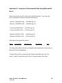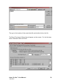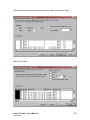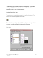
1
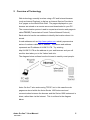
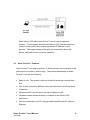
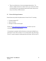
Aztec On-line™ Communications Provided by Severn Trent Services – Severn Trent Water Purification Limited. User Manual Capital Controls Ltd 299.6060.2 Part No: Issue: 04-1005-B APRIL 2003 These instructions describe the installation, operation and maintenance of the subject equipment. Failure to strictly follow these instructions can lead to equipment rupture that may cause significant property damage, severe personal injury and even death. If you do not understand these instructions, please call Severn Trent Water Purification for clarification before commencing any work at 215-997-4000 and ask for a Field Service Manager. Severn Trent Water Purification, Inc. reserves the rights to make engineering refinements that may not be described herein. It is the responsibility of the installer to contact Severn Trent Water Purification, Inc. for information that cannot be answered specifically by these instructions. Any customer request to alter or reduce the design safeguards incorporated into Severn Trent Water Purification equipment is conditioned on the customer absolving Severn Trent Water Purification from any consequences of such a decision. Severn Trent Water Purification has developed the recommended installation, operating and maintenance procedures with careful attention to safety. In addition to instruction/operating manuals, all instructions given on labels or attached tags should be followed. Regardless of these efforts, it is not possible to eliminate all hazards from the equipment or foresee every possible hazard that may occur. It is the responsibility of the installer to ensure that the recommended installation instructions are followed. It is the responsibility of the user to ensure that the recommended operating and maintenance instructions are followed. Severn Trent Water Purification, Inc. cannot be responsible deviations from the recommended instructions that may result in a hazardous or unsafe condition. Severn Trent Water Purification, Inc. cannot be responsible for the overall system design of which our equipment may be an integral part of or any unauthorized modifications to the equipment made by any party other that Severn Trent Water Purification, Inc. Severn Trent Water Purification, Inc. takes all reasonable precautions in packaging the equipment to prevent shipping damage. Carefully inspect each item and report damages immediately to the shipping agent involved for equipment shipped “F.O.B. Colmar” or to Severn Trent Water Purification for equipment shipped “F.O.B Jobsite”. Do not install damaged equipment. SEVERN TRENT SERVICES, COLMAR OPERATIONS COLMAR, PENNSYLVANIA, USA IS ISO 9001: 2000 CERTIFIED Severn Trent Water Purification Ltd. 8 Hawksworth Southmead Industrial Park Didcot Oxon OX11 7HR Copyright ©2002 by Severn Trent Water Purification Ltd. All rights reserved. No part of this manual may be reproduced or transmitted in any form by any means, electronic or mechanical, including photocopying, recording, or by any information storage or retrieval system, without prior written permission from Severn Trent Water Purification Ltd. Notice of Liability Every effort has been made to ensure that this manual contains accurate and current information. However, Severn Trent Water Purification Ltd. shall not be liable for any loss or damage suffered by readers as a result of information contained herein. Trademarks All trades are acknowledged as belonging to their respective companies. Aztec On-line™ User Manual 299.6060.1 2 Table of Contents 1 FURTHER SOURCES OF INFORMATION......................................................................................4 2 OVERVIEW OF TECHNOLOGY..........................................................................................................5 2.1 2.2 2.3 A ZTEC ON-LINE ™ FEATURES .................................................................................................................6 SECURITY ISSUES.......................................................................................................................................7 FACTORS AFFECTING PERFORMANCE .....................................................................................................8 3 LOGGING ON..............................................................................................................................................9 4 THE MAIN PAGE.................................................................................................................................... 10 4.1 5 THE GRAPH PAGES .............................................................................................................................. 14 5.1 5.2 6 M AIN PAGE COMPONENTS......................................................................................................................11 THE GRAPH PAGE ....................................................................................................................................14 DOWNLOADING THE GRAPHS & A NALYSING DATA..........................................................................15 THE SET UP PAGES - CONFIGURING THE MONITOR........................................................ 18 6.1 SUMMARY OF SET -UP PAGES.................................................................................................................20 6.1.1 Set Up: Measurement Settings.................................................................................................. 20 6.1.2 Set Up: Calibration Settings..................................................................................................... 20 6.1.3 Set Up: Outputs Settings............................................................................................................ 20 6.1.4 Set Up: Alarm Relay Assignments............................................................................................ 21 6.1.5 Set Up: Milliamps Settings........................................................................................................ 21 6.1.6 Set Up: Time & Date Settings................................................................................................... 21 6.1.7 Set Up: Base Unit Configuration Settings.............................................................................. 21 6.1.8 Set Up: Advanced Settings ........................................................................................................ 21 7 THE DIAGNOSTIC PAGES - ASSESSING THE MONITOR ................................................... 23 7.1 OUTLINE OF DIAGNOSTICS PAGES.........................................................................................................23 7.1.1 Diagnostics: Monitor Status..................................................................................................... 23 7.1.2 Diagnostics: Error & Events Log ............................................................................................ 24 7.1.3 Diagnostics: Calibration Status............................................................................................... 24 7.1.4 Diagnostics: Alarm Relay Test ................................................................................................. 25 7.1.5 Diagnostics: Cell Diagnostics.................................................................................................. 25 7.1.6 Diagnostics: Level Stick Input Status...................................................................................... 27 8 ENDING YOUR SESSIO N .................................................................................................................... 28 APPENDIX A – ANALYSIS OF DOWNLOADED DATA USING MICROSOFT EXCEL...... 29 APPENDIX B – CONNECTING AN EXTERNAL DEVICE................................................................. 35 Aztec On-line™ User Manual 299.6060.1 3 1 Further Sources of Information Use this manual for help and information about using Aztec On-line™. The other available reference material is outlined below. Setting Up For information about setting up Aztec On-line™, see the Getting Started Guide Operation of Series 1000 For instructions on setting up a Series 1000 instrument and other technical information about the Series 1000 see the Colorimetric or ISE Operation and Maintenance manual. Additional Help Additional help is provided at http://www.capitalcontrols.net/azteconline Aztec On-line™ User Manual 299.6060.1 4 2 Overview of Technology Web technology normally involves using a PC and Internet browser (such as Internet Explorer) to dial-up an Internet Service Provider to ‘surf’ pages on the World Wide Web. The pages displayed on your browser are stored on a remote server and downloaded to your PC. The communication protocol used to request and receive web pages is called TCP/IP (Transmission Control Protocol/Internet Protocol). Each web site has its own address to identify the location where it is stored. A web address such as http://www.yahoo.com actually represents a series of numbers called an IP address. The above web address represents an IP address of 64.58.76.178. Try entering http://64.58.76.178 as the address in your web browser and you will see this also takes you to the Yahoo! web site. The diagram below outlines how the Internet is used by most people: Aztec On-line™ also works using TCP/IP, but in this case the web pages are stored within the Aztec Series 1000 instrument and communication between the browser and the Series 1000 instrument is direct, rather than via the Internet. This is outlined in the diagram below. Aztec On-line™ User Manual 299.6060.1 5 Each Series 1000 with Aztec On-line™ has a unique telephone number. To view pages stored by the Series 1000, dial the telephone number of the monitor and enter a predefined IP address in your browser. The pages displayed will give you information about the Series 1000 and let you control its operation. 2.1 Aztec On-line™ Features Aztec On-line™ is a unique product. It allows remote communication to be performed in a modern, intuitive way. The positive advantages of Aztec On-line™ include the following: • Ease of use. The system looks and feels like browsing a normal web site. • One-to-one connection between user and instrument minimises threat of hackers. • Different security levels can be set up for different staff. • Wireless modem allows flexibility in location of the Series 1000 instrument. • Can be accessed by any PC using a modem and Microsoft Internet Explorer. Aztec On-line™ User Manual 299.6060.1 6 2.2 Security Issues Security is normally a concern when accessing sensitive information across the Internet, for example bank account details. Because this product uses internet technology, the same concerns apply. However, it should be noted that Aztec On-line™ is not actually part of the Internet itself, as there is a direct telephone connection between the browser and the Series 1000 instrument. Aztec On-line™ has a number of important security features built in: • The system uses a direct connection, and is therefore not part of the Internet. In order to gain access to the login screen a hacker must know and dial the instrument’s unique telephone number. • Remote access is password-protected. • Passwords are encrypted before being communicated from the browser to the Series 1000 instrument. • The login system uses an encrypted key system, and has time expiry of both key and Series 1000 login. • The Aztec On-line™ Web-server and TCP/IP stack are both custom implemented. They are therefore a ‘black box’ to hackers. • Multiple access levels allow sections of remote functionally to be permanently disabled, if required. For instance, it is possible to completely block out the ability to reconfigure the instrument remotely, whilst still allowing the Series 1000 to be monitored remotely. Aztec On-line™ User Manual 299.6060.1 7 • There is no skeleton key to circumvent password protection. For instance, Capital Controls are unable to dial up your instrument unless you specifically tell us the passwords and access levels that you have set up in the Series 1000 instrument. 2.3 Factors affecting performance Several factors may affect the performance of Aztec On-line™ including: • Processor speed of PC • Speed of modem • Strength of mobile network signal Please see www.capitalcontrols.net/azteconline for advice if you are concerned about one of these factors. It is important to remember that the first time an instrument is dialled from a particular PC, there will be a delay of 3 to 4 minutes whilst a file which Aztec On-line™ needs to operate is downloaded from the Series 1000 into the PC. Aztec On-line™ User Manual 299.6060.1 8 3 Logging On This section describes the basic procedure for remotely connecting and logging into your Series 1000 instrument. • Connect to the Series 1000 as described in the Aztec On-line™ Getting Started Guide. • At the login page, enter one of the passwords as set up on the Series 1000 monitor and click Submit. • If login is successful, the main page will be displayed. The first time the system is used on a PC, the main page will take 2-3 minutes to download. This is because the PC browser needs to first download a file stored on the Series 1000 for Aztec On-line™ to operate. On second and subsequent times the time taken to display the main page after login will be significantly shorter. Aztec On-line™ User Manual 299.6060.1 9 4 The Main Page This section describes the Aztec Online™ main page. It is from this page that the user gains information relating to the instrument’s current operational status, and clicks to gain access to all other remote features. The Main Page is the first page displayed after logging in to the system. Aztec On-line™ User Manual 299.6060.1 10 4.1 Main page components The components of the main page are described below: The Header Bar 1. Last measurement value taken by monitor 2. Model of monitor, e.g. AZTEC Al1000 Aluminium 3. Current State of monitor, e.g. Off, Measuring, Calibrating The Menu Bar The menu bar is positioned down the lefthand side of all pages. To select a page to visit, just click on the required menu option. Aztec On-line™ User Manual 299.6060.1 11 Graph Section 1. 24-hour graph for measurement stream 1 2. 24-hour graph for measurement stream 2 (for 2 & 3 stream Colorimetric monitors only) 3. 24-hour graph for measurement stream 3 (for 3 stream Colorimetric monitors only) 4. Last measurement value taken by the monitor shown in bold. This value corresponds to the value shown in the header bar. Status Bar Provides information about the current state of the monitor, e.g. Off, Measuring, Calibrating and also alarm and error messages. Aztec On-line™ User Manual 299.6060.1 12 Operation Bar The Operation Bar emulates the Operate menu of the Series 1000 monitor. To change the current operation of the monitor: • Select the required option and then click Change • After a few seconds, the status bar will be updated to confirm new operation has started. • If you do not see this change within 10 seconds, click Change again. ! You must be logged in with full security rights (Level 3) to change operation. Aztec On-line™ User Manual 299.6060.1 13 5 The Graph Pages This section describes additional features of Aztec On-line™ for analysis of stored measurement data. 5.1 The Graph Page To view graph pages in more detail than those shown on the Main Page, select Graphs from the menu. Graph: 24 hours The 24-hour graph for stream 1 will be displayed by default. If the monitor has more than one measurement stream, radio buttons allow further graphs to be selected. Click the required measurement stream and the graph will change within a few seconds. The graph shows the data recorded for the previous 24 hours along with the minimum, maximum and average value for this period. Aztec On-line™ User Manual 299.6060.1 14 Graph: 7 days To view this page, select the 7 Days option. The page will be updated with the 7-day graph within a few seconds. This page functions in the same way as the 24-hour graph, but with data recorded over the previous 7 days. Graph: 28 days To view this page select the 28 Days option. The page will be updated with the 28-day graph within a few seconds. This page functions in the same way as the 24-hour and 7-day graphs, but with data recorded over the previous 28 days. 5.2 Downloading the Graphs & Analysing Data To download the graph data, select ‘Download’ from the menu bar. A new window will be displayed, and you should see the data displayed in the window. Aztec On-line™ User Manual 299.6060.1 15 When all the data has been downloaded the text in the bottom lefthand status bar will change to ‘Done’ as shown below. Now select File > Save As and select File Type as Text. Browse to a location on your PC where you wish to store the file and click OK. Aztec On-line™ User Manual 299.6060.1 16 See Appendix A for details on how to import this data into Microsoft Excel and create graphs from the data. Aztec On-line™ User Manual 299.6060.1 17 6 The Set Up Pages - Configuring the monitor This section describes the facilities of Aztec On-line™ which allows a remote user to alter the configuration of the Series 1000 instrument. The set up pages are accessed from the menu bar and can be used to perform the same functions as would be done on-site. When the pages are displayed on screen, the information on the pages show the current configuration of the monitor. Changes made to the configuration will be transmitted to the monitor when the Submit button on that page is clicked. ! You must be logged in with a minimum of security level 2 to view these pages and with security level 3 to make any changes. Example Configuration This section uses the Set Up: Time & Date Settings as an example of how to operate the set up pages. This page is shown in the diagram below: Aztec On-line™ User Manual 299.6060.1 18 The values contained in the boxes show the time, date and date format that the monitor currently has configured. To change the time, position the cursor in the hours box and enter the new value. Use the TAB key on your keyboard to move to the next box and enter a new value if required. Continue through the page until all required changes have been made, then click Submit. The changes you have made will now be transmitted to the Series 1000 instrument. Within a few seconds the page will be redisplayed to confirm the new values have been accepted by the Series 1000. Restoring Values Altered by Mistake If you change your mind about changing settings part way through, or make any mistakes, click the Reset button to restore the values displayed on the page. Error Checking If any errors have been made when entering data, an error message will be displayed when Submit is clicked. Correct any errors if necessary and click Submit again. Confirming Changes If for any reason you are unsure that the changes made have been successfully, exit the current page by selecting another menu option, then return to the page where changes were made. This will confirm the current settings of the Series 1000 monitor. Note Avoid using the ‘Refresh’ button of your browser to redisplay pages as this may cause values to be unwittingly transmitted. Aztec On-line™ User Manual 299.6060.1 19 6.1 Summary of Set-up Pages The functions of the set-up pages are outlined below. For more details on how to configure the monitor, and what effect changes in these forms will have, see the sections on configuring the monitor in the Colorimetric or ISE Operation and Maintenance manual. 6.1.1 Set Up: Measurement Settings Use this page to set up: • Measurement Rate, i.e. number of measurements per hour (Colorimetric models only) • Chemical Units e.g. N, NH3, NH4 • Measurement Units e.g. mg/l, ppm, ppb • Temperature Units, °C or °F • Cell Temperature. 6.1.2 Set Up: Calibration Settings Use this page to set up: • Calibration Time & Date • Calibration Frequency • Low & High Calibration Standard values • Gradient Deviation • pH Calibration (ISE models only). 6.1.3 Set Up: Outputs Settings Use this page to set up: • Milliamp Output Range • Relay Common Settings (Delay, Hysteresis) Aztec On-line™ User Manual 299.6060.1 20 6.1.4 Set Up: Alarm Relay Assignments Use this page to set up: • Relays to alarm on a particular state 6.1.5 Set Up: Milliamps Settings Use this page to set up: • Low and High Milliamp Output values. 6.1.6 Set Up: Time & Date Settings Use this page to set up: • Time, date and date format of the instrument. 6.1.7 Set Up: Base Unit Configuration Settings Use this page to set up: Note • Instrument model • Language used • Number of measurement streams (Colorimetric only) • Biocide dose option (Colorimetric only). If instrument model is changed, the monitor must restart. This means you will have to log in again when performing this operation remotely. Note The language setting will change the language of the Series 1000 monitor, not the language displayed on the web pages. 6.1.8 Set Up: Advanced Settings Use this page to set up: • Diagnostic Printout • Calibration Fail Event • LED Fail Event (Colorimetric only) Aztec On-line™ User Manual 299.6060.1 21 Note • Number of rinse sequences (Colorimetric only) • Cleaning Mode (Colorimetric only) • Custom stream sequencing (Colorimetric only) Some functions of the Series 1000 monitor are not present in the remote communications package. These are: • LCD Settings. Not present, as changing the monitor’s LCD settings has no consequence when using Aztec On-line™. • Communication Settings. Not present as changes to these settings could affect operation of Aztec On-line™. Therefore, for reliability reasons they are not included. Aztec On-line™ User Manual 299.6060.1 22 7 The Diagnostic Pages - Assessing the monitor This section describes the various Series 1000 diagnostic features that are available remotely. The diagnostics pages are accessed from the menu bar and can be used to perform the same diagnostics as would be done on-site. When the pages are displayed, the information on the pages shows the current state of the monitor. Diagnostic pages are updated every 5-6 seconds to ensure you can view up-to-date information. ! You must be logged in with a minimum of security level 2 to view these pages. 7.1 Outline of Diagnostics Pages An outline of each diagnostics page is given below. For further help on interpreting the information, see the Colorimetric or ISE Operation and Maintenance manual. 7.1.1 Diagnostics: Monitor Status Shows the general state of the monitor including input and output parameters. Aztec On-line™ User Manual 299.6060.1 23 7.1.2 Diagnostics: Error & Events Log Provides a log of up to 50 of the most recent errors and events. Note For advanced details of the errors and how they may have been caused, see the Colorimetric or ISE Operation and Maintenance manual. 7.1.3 Diagnostics: Calibration Status Gives real-time information as monitor is calibrating Aztec On-line™ User Manual 299.6060.1 24 7.1.4 Diagnostics: Alarm Relay Test Alarm relays can be individually Set or Reset. To change relay status click the drop-down menu box for the required relay and select the new state. Note This will override the current monitor operation, and monitor will go into OVERRIDE mode. This is a very powerful feature and if in doubt consult your Capital Controls representative before using this facility. ! You must be logged in with full security rights (Level 3) to perform an alarm relay test. 7.1.5 Diagnostics: Cell Diagnostics Colorimetric Monitors This page shows the current cell state and can be used to change how the monitor is working e.g. bring in /out any reagent/sample in any quantity in any order. To do this select the operation, port and enter a volume. Then click Operate . You should see the Current Step and Detector Voltage change accordingly. Aztec On-line™ User Manual 299.6060.1 25 ISE monitors Use this page to test the motor, heater and pinch valves. To change the current status, select option from the drop-down menu. Note Cell Diagnostics procedures will affect the functions of the monitor and will OVERRIDE the current state. This is a very powerful feature and if in doubt consult your Capital Controls representative before using this facility. Aztec On-line™ User Manual 299.6060.1 26 ! You must be logged in with full security rights (Level 3) to perform any cell diagnostics. 7.1.6 Diagnostics: Level Stick Input Status Use to check the level switch inputs to check that samples and reagents have not ran out. Note There are some Series 1000 screens that have been excluded from the Aztec On-line™ package because the diagnostics involve the use of an external device. These screens are: • Milliamp Test • Milliamp Calibration These screens would not be useful remotely so have not been included as part of Aztec On-line™. Aztec On-line™ User Manual 299.6060.1 27 8 Ending Your Session When you have finished your session with the Series 1000 instrument click Logout on the menu bar. You will then be returned to the Login page. Close down Internet Explorer, then disconnect the connection in the Dial-Up Networking folder by right-clicking the telephone entry and selecting Disconnect. Aztec On-line™ User Manual 299.6060.1 28 Appendix A – Analysis of Downloaded Data Using Microsoft Excel Data is saved as a text file in semi-colon delimited format. If you open the form in Notepad you will see the data looks like this: 1;24 Hour;15/5/2000 09:00; 0.010503;mg/l Al 1;24 Hour;15/5/2000 09:05; 0.010503;mg/l Al 1;7 Day;15/5/2000 09:00; 0.010503;mg/l Al 1;7 Day;15/5/2000 10:00; 0.013706;mg/l Al 1;28 Day;15/5/2000 12:00; 1.004039;mg/l Al 1;28 Day;15/5/2000 16:00; 1.015047;mg/l Al When split up into parts this shows: Stream 1 Type of Graph 24 Hour Date and Time 15/5/2000 09:00 Measurement 0.010503 Units mg/l Al The semi-colons allow each part of the data to be entered into its own cell in a Microsoft Excel spreadsheet. To open the file in Excel, first open Excel then select Open from the File menu. In the File Open box, go to Files of Type and select Text Files. Aztec On-line™ User Manual 299.6060.1 29 Then go to the location of the saved data file and double click on the file. The Excel Text Import Wizard should appear on the screen. For the first step, select ‘Delimited’ then click ‘Next’ Aztec On-line™ User Manual 299.6060.1 30 Then select Semicolon and deselect all other options and press ‘Next’ Now click ‘Finish’: Aztec On-line™ User Manual 299.6060.1 31 The data should now be clearly presented in a spreadsheet. If any data is missing and ‘######’ is in its place then column width will need to be increased in order to view all the data properly. Creating Graphs from Data The easiest way to present data in a graph is to use the chart wizard. The icon for this is normally displayed in the toolbar: First select the required style of graph. This may depend on the type of data you have. For further information see Microsoft Excel Help. Click ‘Next’: Aztec On-line™ User Manual 299.6060.1 32 To display a graph of measured values against time, highlight cells in the date and time column and the measurement column, and then select ‘Columns’: You can then give your graph a title and label the axes. Additional formatting can also be done here. Aztec On-line™ User Manual 299.6060.1 33 You can now specify whether you would like the graph to be part of the current spreadsheet, i.e. to be displayed with the data, or to be displayed as a separate chart. Now click ‘Finish’. Additional formatting can also take place once graph is displayed e.g. legend, axes, plot area, by clicking on the relevant area and using the Format box to make changes. See Microsoft Excel Help for more details. Aztec On-line™ User Manual 299.6060.1 34 Appendix B – Connecting an external device There may be occasions when you wish to attach a PC or printer to your Series 1000 instrument for diagnostic purposes. Please note you cannot have an external device attached and Aztec On-line working at the same time. To attach a PC or printer, use appropriate serial cable to connect the device to the RS232 connections of the I/O board inside the Series 1000. For more details see the Colorimetric or ISE Operator manual. Disconnect the white serial cable (A) from the main processor board (2). Connect the white serial cable (B) between the I/O board (3) and the main processor board (2). On the Series 1000 instrument, go to Set Up > Comms > Device and change device from Aztec On-line to PC or printer. Exit from this screen and go into ‘Settings’ screen and change settings if necessary. Communication with external device should now be successful. Remember to change settings back in order for Aztec On-line to function correctly again. Aztec On-line™ User Manual 299.6060.1 35 - 36 - 299.6030.3 Design improvements may be made without notice. Represented by: CAPITAL CONTROLS Severn Trent Services 3000 Advance Lane Colmar, PA 18915 Tel: 215-997-4000 • Fax: 215-997-4062 Web: www.severntrentservices.com E-mail: [email protected] UNITED KINGDOM • UNITED STATES • HONG KONG INDIA • ITALY • MALAYSIA 08/06 299.6060.2 Copyright 2004 Severn Trent Services - 37 -