1
US 20060245618A1
(19) United States
(12) Patent Application Publication (10) Pub. No.: US 2006/0245618 A1
Boregowda et al.
(43) Pub. Date:
(54) MOTION DETECTION IN A VIDEO STREAM
(75)
(30)
Inventors: Lokesh R. Boregowda, Bangalore (IN);
NOV. 2, 2006
Foreign Application Priority Data
Apr. 29, 2005
Mohamed M. Ibrahim, Kayalpatnam
(IN); Mayur D. Jain, Akola (IN);
(IN) ............................... .. l06l/DEL/2005
Publication Classi?cation
Venkatagiri S. Rao, Bangalore (IN)
(51)
Int. Cl.
G06K 9/00
HONEYWELL INTERNATIONAL INC,
(52)
U.S. Cl. ............................................................ .. 382/107
101 COLUMBIA ROAD
(57)
Correspondence Address:
P 0 BOX 2245
(73)
Assignee:
ABSTRACT
.
MORRISTOWN, NJ 07962_2245 (Us)
11/223,177
(22) Filed:
Sep. 9, 2005
.
.
.
extracting color information to estimate regions of motion in
tWo _ or more sequential
Video frames, extracting
edge
infor
_
_
_
_
_
mat1on to estimate object shape of the moving object in tWo
or more sequential Video frames; and combining the color
information and edge information to estimate motion of the
object.
Set p1x_c0unt — 0
Set Bg_?ag = 0
Store ?rst image (after neighborhood
averaging) as Bg_image and
old image( fn-5 )
@mmmghgp
q)‘10c:a on
sequential array and
check the previous
condition only for thCS6
~
1
.
A moving object is detected in a Video data stream by
Honeywell International Inc.
(21) Appl, NQ;
(2006.01)
*in
NO
If pix_count
= = image size
Patent Application Publication Nov. 2, 2006 Sheet 1 of 9
Fig. 1
a
1
Set p1x_c0unt = 0
Set B g_?ag = 0
Store ?rst image (a?er neighborhood
averaging) as Bg_image and
ld
5
Colurnn(q) looation in a
sequential array and
check the previous
condition only for these
esp d
If pix_count
I = image size
US 2006/0245618 A1
Patent Application Publication Nov. 2, 2006 Sheet 2 0f 9
Fig. 2
n / (fn + Bg_img )
Set Low_threshold = k2* mean_Div_img
w
'
Div_img(p,q) <
Low_thresho1d
OR Div_img(p,q)
> High threshold
‘ iBiiiliihéiQciSi
>
US 2006/0245618 A1
Patent Application Publication Nov. 2, 2006 Sheet 3 of 9
,r ‘ along horizontal direction‘
zewiim.
‘t ~ ~w ,
‘hm-‘Y
s
. alongvertiqa direction
.Iz'“ .
-
‘
:
was;
“$1531.?
‘viz-<1?‘
Edge_Strength__Current_Image and
Edge_Strength Div Ima e
both Current image and Division im ge to ?x
different threshold for each i
Check
Edge_Strength_Current_Image(p,q)
> Thresholdl &&
Edge_Strength_Div_Image(p,q)
> Thresh0ld2
‘Edee‘
"
US 2006/0245618 A1
‘
Patent Application Publication Nov. 2, 2006 Sheet 4 0f 9
US 2006/0245618 A1
Figure 4
Check
Edge_Strength_Bin_Image(p,q)
+ Binary_lmage(p,q : 510
'_ N°
Bin_lmage(p,q) == 255
&& Start_?a ———
Yes
Bin iinage(fa,q) = 0
was: i
Yes
V
~
Check
Bin_Image(p,q) +
Edge_S'trength_Bin_Image(p,q)
= 0 && Start ?ag =
“ seiistiartjlag =0 v
No
Patent Application Publication Nov. 2, 2006 Sheet 5 0f 9
US 2006/0245618 A1
Patent Application Publication Nov. 2, 2006 Sheet 6 of 9
US 2006/0245618 A1
Fig. 6
Edge Model
No. of Object > 0
Color Model
Contrast & Edge
Strength Model
Re?ne Motion Segmented Output (Binary) BC & BCl
Based on of Objects in Color and Edge Model
Post Processing
(Median Filter, Region Labeling, Hole Filling)
Final Binary Map
(B = BC ||BC1 ll BE || BEl)
‘l
END
Patent Application Publication Nov. 2, 2006 Sheet 7 0f 9
Fig. 7
1 = f(RGB )
l
i
Y —> EdgeFilter (EF) —> X
l
X —) SabelFilte r(SEF) —-> S
1
Edge Mean Update
HSHQI) (x, y) : aErlgeSH(n) (x, y)+(l_aEdge)1uSH(n)(x> y)
llsvmb?y) : aEdgeSV(n)(x!y) + (1 - aEdge )llswn) (XJ)
Mean Update
A1 I |.uSH(n)(xry) - SH(n)(-x:y)|
Delta Gradient
A12 = |Al —A2|
US 2006/0245618 A1
Patent Application Publication Nov. 2, 2006 Sheet 8 of 9
Fig. 8
1 = f(RGB )
i
Y = 0.29911 + 0.5876 + 0.11413
+
Adaptive threshold am
a :
am, =(a +1/a)/2
mm
+
AC=|Y(,.,(x,y>-#<n)<x,y>|
Generate Binary Color Segmentation Map (BC)
US 2006/0245618 A1
Patent Application Publication Nov. 2, 2006 Sheet 9 of 9
US 2006/0245618 A1
Fig 9
1 = [(RGB )
J,
Y = 0.299R + 0.587G + 0.114B
Jr
Y —> SmoothlmagaFilte?SEF) —> lS'I
J,
J.
J,
Background Learning
Edge Strength (ED) Calculation
r
C
AED lThr =(
AED] ('1) )* kl/rc kl : constant
F0 y=0
i
Generate Binary Color Con?dence Map (BCl)
i
Binary Edge Segmentation Map (BEl)
Nov. 2, 2006
US 2006/0245618 A1
MOTION DETECTION IN A VIDEO STREAM
BRIEF DESCRIPTION OF THE FIGURES
CROSS REFERENCE TO RELATED
APPLICATIONS
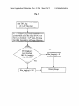
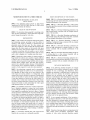
[0008] FIG. 1 is a ?owchart illustrating learning a back
ground image for video motion detection, consistent with an
example embodiment of the invention.
[0001] This application claims priority to India Patent
Application No. l06l/DEL/2005, ?led Apr. 29, 2005, which
is incorporated herein by reference.
FIELD OF THE INVENTION
[0002] The invention relates generally to analyzing video
data, and more speci?cally to motion detection using back
ground image processing for video data.
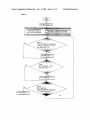
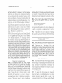
[0009]
FIG. 2 is a ?owchart illustrating a video motion
detection algorithm consistent with an example embodiment
of the invention.
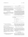
[0010]
FIG. 3 is a ?owchart illustrating generation of an
edge strength image, consistent with an example embodi
ment of the invention.
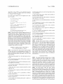
[0011]
FIG. 4 is a ?owchart illustrating combination of
edge strength image data and binary image data, consistent
BACKGROUND
[0003] Video cameras are commonly employed in security
and monitoring systems, providing a user the ability to
monitor a wide variety of locations or locations that are
physically remote from the user. The video cameras are
often also coupled to a video recorder that records periodic
images from the video camera, or that records video upon
detection of motion. Such systems enable a user to monitor
a location in real-time, but also enable a user to review
events that occurred at a monitored location after an event,
such as after a burglary or to con?rm some other event.
[0004] Monitoring a large number of cameras requires a
large number of monitors, and a number of guards su?icient
to keep an eye on each monitor. Simply employing more
with an example embodiment of the invention.
[0012]
FIG. 5 is a ?owchart illustrating a method of
updating a background image, consistent with an example
embodiment of the invention.
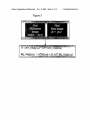
[0013] FIG. 6 is a ?owchart illustrating combination of
color and edge information to estimate motion in a video
stream, consistent with an example embodiment of the
invention.
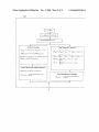
[0014]
FIG. 7 is a ?owchart illustrating ?nding an edge of
a moving object in a video stream, consistent with an
example embodiment of the invention.
facturing plants, military bases, and other large environ
[0015] FIG. 8 is a ?owchart illustrating application of a
color/luminance motion detection algorithm to video motion
detection, consistent with an example embodiment of the
invention.
ments is not a desirable solution because of the additional
cost involved, and so automated solutions to monitoring a
DETAILED DESCRIPTION
monitors and more guards in large facilities such as manu
number of video signals for events have been explored.
[0016] In the following detailed description of example
[0005] One technology commonly used to automatically
embodiments of the invention, reference is made to speci?c
monitor video signals for activity is use of a motion detec
tion algorithm to detect when one or more objects in the
video signal are moving relative to a background. Such
examples by way of drawings and illustrations. These
systems can be used to monitor for intrusion or unauthoriZed
activity in the ?eld of a variety of video cameras, and alert
a user upon detection of motion in the video stream. For
example, such a system may monitor twenty video streams
for motion, and upon detection of motion in one of the video
streams will sound an alarm and display the video signal
with detected motion on a video display.
[0006]
The reliability and accuracy of video motion detec
examples are described in su?icient detail to enable those
skilled in the art to practice the invention, and serve to
illustrate how the invention may be applied to various
purposes or embodiments. Other embodiments of the inven
tion exist and are within the scope of the invention, and
logical, mechanical, electrical, and other changes may be
made without departing from the subject or scope of the
present invention. Features or limitations of various embodi
ments of the invention described herein, however essential
to the example embodiments in which they are incorporated,
do not limit the invention as a whole, and any reference to
tion is therefore important to ensure that such systems
provide adequate security, and can be relied upon to monitor
the invention, its elements, operation, and application do not
video signals for unauthoriZed activity in place of human
security personnel. False detections of motion should there
example embodiments. The following detailed description
fore be kept to a minimum to ensure that detected motion
events justify attention and intervention of security person
nel. Further, the detection probability should be as high as
possible, to ensure that unauthorized motion events do not
go undetected. The motion detection system should further
be insensitive to environmental variations such as snow,
rain, and cloudy weather, and should work in a variety of
lighting conditions. Accurate motion detection is also impor
tant in systems in which motion detection is a part of a more
sophisticated process such as object tracking or identi?ca
tion and video compression.
[0007]
It is therefore desirable that video signal motion
detection be as accurate as is technically practical.
limit the invention as a whole but serve only to de?ne these
does not, therefore, limit the scope of the invention, which
is de?ned only by the appended claims.
[0017] In one example embodiment of the invention, a
moving object is detected in a video data stream by extract
ing color information to estimate regions of motion in two
or more sequential video frames, extracting edge informa
tion to estimate object shape of the moving object in two or
more sequential video frames; and combining the color
information and edge information to estimate motion of the
object.
[0018] Detection of moving objects is an important part of
video camera based surveillance applications. Many
examples of video motion detection algorithms employ
Nov. 2, 2006
US 2006/0245618 A1
background subtraction to detect any activity or motion in
the scene. Therefore, it is desirable to ?rst learn the static
background scene that does not contain any moving fore
pixels. In the next video frame, the pixels Which are not
learnt earlier are only considered and the process is repeated
ground objects. If there are foreground objects that are
moving continuously in the scene, then it becomes a prob
lem to identify and learn the static background scene.
Various embodiments of the present invention address this
problem, such that the learnt background can be used to
background. Once the background is fully learnt the algo
implement subsequent motion detection algorithms. In fact,
the same method can be applied to continuously update the
background, once the initial learning phase is completed.
[0019] In one example, instead of using conventional
image subtraction approach for motion detection, the current
image is divided by the sum of current image and learnt
background image to generate a division image. The divi
sion image is subjected to a threshold operation to get the
motion detected image. Further robustness is achieved by
combining the motion detected image With the edge strength
image. The method is described beloW.
[0020] In the ?rst step, the color image obtained from the
camera is converted into a grayscale image and the resulting
gray level image is passed through an averaging ?lter such
over a number of frames until the entire image is learnt as
rithm declares that the background is learnt and it sWitches
to a video motion detection (VMD) routine.
[0022] If the gray level value at a given pixel location is
fn(p,q) at time t, and fn-5(p,q) at time t-5 (?ve frames
earlier), the sum and difference images are obtained as
folloWs.
Difference image: Difiimg=abs(fn—?1—5)
Sum image: Surniimg=(?1+?1—5)
(1)
(2)
Thresholdiim g=k1 * Sumiirn g
(3)
k1=Constant multiplying factor Which decides the gray level
variation betWeen the tWo video frames that can be alloWed
to qualify a given pixel as a background pixel or not. It is
chosen in the range of 0.0001 to 0.001.
[0023] The value of each and every pixel in the Dif_img
is compared With a corresponding pixel in the Thresh
old_img and if a given pixel is less than the Threshold_img
value, it is considered as static background pixel.
as a 3x3 neighborhood averaging ?lter to reduce the effect
of noise. This ?ltered image is referred to as current image
in the subsequent discussions. The second step involves
learning the static background scene, and for this purpose
the current image and the image Which Was captured ?ve
frames earlier are used. The algorithm is designed to pick up
only static background pixels and reject those pixels Which
correspond to moving objects in the foreground. In the third
step, this learned background image along With the current
If Difiirng(p,q) < Thresholdiirng(p,q)
Bgiimgwn) = fn(p,q)
[0024] Where Bg_img(p,q) is the learnt background image
pixel, ‘p’ indicates roW and ‘q’ indicates column number.
image are utiliZed to generate a division image. In the fourth
[0025] The location (roW ‘p’ & column ‘q’) of all the
step, the division image is subjected to a threshold operation
to get a segmented binary image Wherein all the background
pixels Which do not satisfy the above condition is stored in
a sequential array. In the next frame, only those pixels Which
pixels are set to Zero and the moving foreground pixels are
are available in the sequential array are tested for the
set to 255. The ?fth step involves generating edge strength
image for both division image and the current image. The
sixth step involves ?nding the correspondence betWeen the
above(If) condition and the process is repeated in every
binary image and the edge strength image. The output from
this step is subjected to median ?ltering in the seventh step
to get ?nal segmented binary image output. The eighth step
involves subsequent updating the background pixels using
the current image and the image that Was captured ?ve
frame till the number of learnt background pixels is same as
the image siZe. Then it declares that the background is learnt.
This learnt background image is use in the subsequent Video
Motion Detection algorithm. FIG. 1 shoWs a ?owchart of
one example method of learning a background image, con
sistent With the example embodiment of the invention
described above.
frames earlier. Further details of individual steps in one
speci?c example embodiment are given beloW.
Video Motion Detection
Background Learning Mechanism
[0021] The background learning used in the example
[0026] For motion detection, the current image is typically
subtracted from the background image, and the background
video motion detection algorithm, Works as folloWs. When
We monitor a given scene over a period of time, any object
the moving foreground pixels. In some embodiments of the
present invetntion, We normaliZe the current image by
dividing it With the sum of current image and the back
Which is moving Would normally result in considerable
change in gray level at those pixel locations, Whereas in the
areas Where there is no activity or motion, gray level value
subtracted image is evaluated using a threshold to extract all
ground image and the resulting division image (Div_img) is
used for extracting the moving foreground pixels from the
of the pixels remains almost same. To monitor this change
in gray levels, We have considered difference image and sum
image that are obtained using the current image and old
static background pixels.
image (5 frames old), and the difference image is thresh
[0027] To segment this division image into background
and moving foreground pixels (target pixel), it is desired to
olded using a scaled version of sum image. This method of
thresholding has been found to be robust to change in
illumination levels of the scene. Those pixels in the differ
ence image that are beloW the threshold are considered as
Diviimg=?1/(Bgimg+?1)
(4)
subject the image to a thresholding operation. It is evident
from the above equation (Equation No. 4) that all those
pixels in the current image (fn) Which are equal to the
background pixels and hence the pixels in the corresponding
corresponding pixels in the background image (Bg_img)
locations of the current image are learnt as background
Would yield a value of 0.5 in the Div_img; Whereas all target
Nov. 2, 2006
US 2006/0245618 A1
pixels show up as deviations on either side of this mean
[0032] Similarly Edge_Strength_Div_lmage is
value (0.5). However, it is advisable to ?nd this mean value
from the image itself as there could be variations in light
levels from frame to frame. Hence, the mean gray level of
the division image (Div_img) Was ?rst determined. While
?nding the mean, those pixels that are in the neighborhood
obtained for division image. After this step, mean grey level
of 0.5 (0.4 to 0.6 range) Were only considered. After getting
the mean gray level value of the division image, it is
multiplied by tWo different constants (k2 and k3) to generate
also
of Edge_Strength_Current_Image and Edge_Strength_Di
v_Image are separately determined to compute separate
thresholds for both the edge strength images. Let us call
Thr1 and Thr2 as thresholds for Edge_Strength_Current_I
mage and Edge_Strength_Div_lmage respectively. Using
these tWo thresholds simultaneously, a single Binary_Edge
_Image is obtained using the folloWing logic.
loWer and upper threshold as indicated beloW.
High threshold=k2*meaniDiviimg
LoWithreshold=k3*meaniDiviimg
(5)
(6)
If ( EdgeiStrengthiCurrentiImagdp,q) > Thrl &&
EdgeiStrengthiDiviImage(p,q) > Thr2 )
[0028] In our implementation, the value of k2 and k3 are
chosen as 1.1 and 0.9 respectively, assuming a 110% spread
Else
BinaryiEdgeiImage(p,q) = 255
BinaryiEdgeiImage(p,q) = 0
around the mean for background pixels. This assumption
proved to be a valid one When tested on a variety of video
data sets. Alternatively, the values of k2 and k3 can be
chosen by computing the standard deviation of those pixel
gray levels that are used for ?nding the mean value. The
loWer threshold operates on those object pixels that are
Where p,q are the roW and the column indices of a given
pixel in the image under consideration. The ?owchart of
FIG. 3 illustrates this method of generation of an edge
strength image.
darker than the background and the higher threshold oper
Combining Edge_Strength_Binary_Image With the
Motion Detected Binary Image
ates on the object pixels that are brighter than the back
ground.
[0029] Segmentation of image into background and target
regions is done by comparing each and every pixel With high
and loW thresholds as per the logic given beloW.
[0033] To eliminate spurious pixels in VMD output, the
correspondence betWeen the edge strength image and the
VMD output (binary blobs) is established using three “If
Else” loops as explained beloW. For this, the VMD binary
image and the edge strength image are scanned from left to
right along top to bottom direction roW by roW. Initially a
If [ Diviimg(p,q) < LOWfLhl‘?ShOld OR Diviimg(p,q) >
Highithreshold ]
Biniimg(p,q) = 255;
Biniimg(p,q) = 0;
Else
[0030] Bin_img is the segmented binary image, Wherein
all pixels indicating 255 correspond to moving foreground
pixels and pixels With Zero values correspond to background
region. The ?owchart of the VMD algorithm is given in
FIG. 2.
?ag knoWn as Star‘t_?ag is set to Zero and the VMD output
is copied into tWo arrays knoWn as Bin_imgl and Bin_img2.
Biniimgl = Biniimg;
Biniimg2 = Biniimg;
If (( Biniimg1(i,j) + Edgeiimg(i,j) == 510 ) & (Starti?ag == 0 ))
Starti?ag = 1;
Else
End;
If (Starti?ag == 0) & (Biniimg1(i,j) == 255)
Generation of Edge Strength Image
[0031]
If an object that is learned as background earlier
starts moving, then it shoWs up as tWo objects; one at the
neW location and one at the location Where it Was residing
earlier. This happens because it takes a certain amount of
Else
End;
If( Starti?ag == 1) & ( Biniimg1(i,j) + Edgeiimg(i,j) == 0)
Starti?ag = 0;
Else
End;
time to learn the exposed background area Where object Was
residing earlier. This problem can be avoided if We somehoW
combine the current edge image With the binary image
output of motion detection routine. This is done by ?rst
extracting the edge strength image Which is common to both
division image and the current image. The actual procedure
involves ?nding the roW difference and column difference
image and combining both as explained beloW.
Star‘t_?ag is set to Zero at the beginning of each and every
roW before applying the “If, Else” condition. i,j are the roW
and column indices of a given pixel in the images under
consideration. Similarly, Bin_img is modi?ed by traversing
in the right to left direction. AfterWards, ?nal binary image
is obtained by doing an “OR” operation on the tWo binary
grayiimageirowdif?p,q)=grayiimageiro(p+1,
images. Bin_img=Bin_img1 OR Bin_img2. This method of
q)—grayiimageiro ([7,1]); for all the roWs over the entire
combining the edge strength image data and binary image
Find
image.
Find
data is illustrated in FIG. 4.
grayiimageicoldii?p,q)=grayiimageicol(p,q+
1)—grayiimageicol(p,q); for all the columns over the
Background Update
entire image.
Find EdgeiStrengthjCurrentiImage(p,q)=Sqrt[(gray—
Timageirowdi?“(p,q)) 2+(grayiimageicoldiff(p,q) )
2]
[0034]
There is a need to update the learned background
scene as one cannot be sure of some image characteristics
such as the same level of illumination over an extended
Where p,q are the roW and the column indices of a given
period of time. Also, an object that Was stationary during the
pixel in the image under consideration.
learning period may start moving at a later time or a neW
Nov. 2, 2006
US 2006/0245618 A1
object may enter the camera ?eld of vieW and remain
stationary for a long period. Under such circumstances, it is
desired to update the learnt background scene to have
effective motion detection. The procedure adapted for updat
ing the background is given beloW.
[0035] Similar to the initial learning of background, the
current image (fn) and the image Which is ?ve frames old
(fn-5) are used to obtain Di?‘_img and Sum_img( Equations
1&2). If a given pixel in the Dilf_img satis?es the folloWing
inequality condition, then the previous background image at
that location is replaced by the Weighted sum of present
image and the previous background image.
Where,
[0039]
[0040]
[0041]
[0042]
[0043]
[0044]
[0045]
[0046]
n=nth frame
Y(n)(x,y)=Luminance
G(n)(x,y)=Green pixel
p.(n)(x,y)=pixel mean at position x,y
AC=mean difference Image
R(n)(x,y)=Red pixel
B(n)(x,y)=Blue pixel
otavg=Learning parameter
Adaptive threshold computed using the current frame and
previous frame difference and the mean of the difference
as given beloW
(14)
0t=Learning rate for the background pixels. The value of 0t
can be varied betWeen ‘zero’ and ‘one’ depending on the
required learning rate. k1=Constant multiplying factor as
chosen in the earlier background learning routine (Equation.
1). This updated Bg_img is used in the next frame to obtain
the Div_img in the VMD routine and the Whole process
repeats. This method is shoWn in ?owchart form in FIG. 5.
[0036] The method described above is an example
embodiment of the present invention illustrating hoW extrac
Where,
[0047]
r=roWs, c=columns
The average alpha over the frames is used for background
model update
tion of various information from a video stream can be used
to effectively detect motion for applications such as security
monitoring and object identi?cation.
A Second Algorithm Example
avg
avg
[0048] The value of ‘Alpha’ is normalized based on the
count of the motion pixels only. The variation of thus
computed ‘Alpha’ is shoWn in the plot shoWn above and
varies most appropriately according to the extent of the
[0037]
In another example, color and edge information are
extracted from the video frame sequence to estimate motion
of an object in a video stream. The color information is used
as the ?rst level cue to extract motion regions. These motion
regions/blobs usually do not account for the full shape &
contour of the moving object. The incomplete blobs thus
obtained from the color model, are boosted by second level
processing using the edge information. The ?nal motion
segmented result is then obtained as the collated information
motion in the frame. Whenever fast moving objects/sloW
moving objects are encountered, alpha increases or
decreases respectively for the most optimal update of the
BGND.
Background Learning Mechanism
[0049] The background learning Which forms the back
bone of the second example algorithm is based on a hier
of the color and edge foreground con?dence maps.
archical fusion of a) color and b) edge models obtained
corresponding to the pixel-state using its RGB color & Edge
[0038] This second video motion detection algorithm
information as shoWn in the ?owchart of FIG. 6.
involves the generation of the mean and variance images
(computed pixel-Wise) based on the color & edge informa
tion of each of the frames in the video data. These mean and
variance images are then updated dynamically using the
method of moments to help build the color & edge models
respectively. The models basically learn the background
information in the frames. These models are then threshold
Edge Model
[0050] The color model does not give the smooth edge. To
get the ?ne edge of the object to improve the result, edge
model is applied to Y channel as given beloW. An edge
sharpening ?lter is ?rst applied on the Y channel image data.
ed using standard deviation information to conclude Whether
a pixel belongs to the foreground (FGND) or background
(BGND) leading to the formation of motion con?dence map.
The algorithm ?oW for the color (or Luminance) and edge
based analysis is described in the How diagram shoWn
[0051] Output X obtained after passing through the high
pass ?lter is fed to Sobel ?lter to get the horizontal and
vertical edges. The mean and the zero mean are computed
for the each channel as
beloW. The method starts With the computation of the mean
and difference images for the current frame at each pixel as
given by the equations,
[0052] SH(x,y)=Sobel Horizontal edge data
[0053] SH(x,y)=Sobel vertical edge data
Nov. 2, 2006
US 2006/0245618 A1
[0054] uSH(n)(x,y)=Sobel Horizontal mean
[0055] uSV(n)(x,y)=Sobel Vertical mean
[0056] otEdge=Constant
[0057]
Difference image: Diffilmage=abs(fn(x,y)—f(ni5)(x,y))
(24)
Sum image: SumiImage=fn(x,y)+?ni5)(x,y)
(25)
Thresholdilmage=kl * Sumflmage
(2 6)
Where, Constant k1=Multiplying factor, which decides the
The mean and delta gradient images are computed
gray level variation between the two video frames that can
be allowed to qualify a given pixel as a background pixel or
not. It is chosen in the range of 0.0001 to 0.001.
for the horizontal and vertical Sobel image as below
Mean gradient
[0062] The value of each and every pixel in the Di?f_lm
age is compared with a corresponding pixel in the Thresh
old_lmage and if a given pixel is less than the Thresh
old_lmage value, it is considered as static background pixel.
Binary Edge segmentation map is obtained using the ?xed
If Diffilmagdx, y) < Thresholdilmagdx, y) ,
threshold as given below
BgndJmageW y) = 120% y)
( 27a)
Binary Edge Con?dence Map (BE)
Where,
BE” x,
()( y)
:
1 Azrhr
Bgnd_lmage(x,y) is the learnt background image pixel, ‘x’
0 Otherwise
indicates columns & ‘y’ indicates rows.
[0063] The location(x,y) of all the pixels which do not
Morphological operators are then applied on the edge map.
The overall ?ow of the Edge model is shown in the ?owchart
of FIG. 7.
Color/ Luminance Model
[0058] For Luminance(Y) channel, background model is
build using the weighted sum of mean and the current pixel
value
p'(n)(‘x1y)=0'avgY(n)(‘x1y)+(1 _o'avg)p'(nil)(xly)
(22)
A difference mean image is computed which is used to
threshold and segment the image as foreground or back
satisfy the above condition is stored in a sequential array. In
the next frame, only those pixels that are available in the
sequential array are tested for the above “If’ condition and
the process is repeated in every frame till the number of
learnt background pixels is same as the image siZe.
[0064] To avoid the appearance of artifacts occurring due
to illumination changes during the process of learning, after
the above mentioned threshold comparison step (17a), the
following steps are carried out in every frame using the
above Di?f_lmage, Sum_lmage, Threshold_lmage and Bgn
d_lmage.
ground
AC=Y<n>(x,y)—P<n>(x,y)
(23)
Binary Color Con?dence Map (BC)
BC” x,
()( y)
:
1 AC2 l/aavg Foreground
0 Otherwise
Background
If Diffilmage(x, y) < Thresholdilmagdx, y)
The value of ‘0t’ is chosen as 0.9.
[0065] Above analysis until the step-17a is used during the
initial background learning phase of the algorithm and if the
[0059]
The color/luminance model evaluation process is
further summariZed in the ?owchart of FIG. 8.
Contrast Model
[0060] The images are initially subjected to a pre-process
ing step, wherein RGB to Gray (intensity or luminance)
conversion is carried out, and this image is passed through
an averaging (3x3 neighborhood averaging) ?lter. The aver
aging ?lter smooth-en the image and helps in reducing the
e?fect of noise.
[0061]
If the gray level value at a given pixel location is
fn(x,y) at time t, and f n_5)(x, y) at time t-5 (?ve frames
earlier), the sum and di?ference images are obtained as
follows.
number of learned background pixels is same or comparable
to the image siZe, the algorithm sets the ?ag indicating
completion of learning process. Further to this, the same
steps until the step-17a along with the step-17b together
perform moving object segmentation. The procedure
adapted for updating the background is described below.
[0066] Similar to the initial learning of background, the
current image (fn) and the image which is ?ve frames old
(f(n_5)) are used to obtain Di?f_lmage and Sum_lmage
(Equations 14 & 15). If a given pixel in the Di?f_lmage
satis?es the following inequality condition, then the previ
ous background image at that location is replaced by the
weighted sum of present image and the previous background
image.
Nov. 2, 2006
US 2006/0245618 A1
-continued
If DiffiIrnage (x, y) < kl * SuIniImage (x, y)
BgndiIrnage(x, y) = (1* BgndiIrnage(x, y) + (l—0t)* fn(x, y) ———— ( 28 )
Else
BinaryiEdgeiImagdx, y) = 0
0t=Learning rate. Value of 0t can be varied between ‘Zero’ &
Where x, y are the roW and the column indices of a given
‘one’ depending on required learning rate. Where, Constant
k1=Multiplying factor as chosen in the earlier background
pixel in the image under consideration.
learning routine (Eqn. 14). This updated Bgnd_Image is
Combining Edge Strength Model Information With
used in the next frame to obtain the Div_Image in the VMD
routine and the Whole process repeats.
Contrast Model Information
Edge Strength Model
[0067]
The procedure involves computing the roW differ
ence and column difference images and combining both as
detailed beloW. Compute the RoW and Column difference
[0069] To eliminate spurious pixels in video motion detec
tion output, the correspondence betWeen the Edge_Strength
_Bin_Image and the video motion detection output (binary
blobs) is established in one example embodiment by using
three “if-else” loops as explained beloW. For this operation,
the video motion detection binary image and Edge_Image
are scanned from left to right along top to bottom direction
images respectively as,
roW by roW. Initially a ?ag knoWn as Start_Flag is set to Zero
Grayelmageecoldimx’ y)=f"(x+1’ y)_f"(x’ y)
GrayiImageiRoWdifRx, y)=fn(x, y+l)—fn(x, y)
(29)
(30)
and the video motion detection output is copied into tWo
arrays knoWn as Bin_Imagel and Bin_Image2.
Start Flag 0;
BiniIrnagel = BiniIrnage
BiniImage2 = BiniIrnage
If ((BiniImagel(x, y) + EdgeiIrnage(x, y) == 510) & (StartiFlag == 0))
StartiFlag ==
;
Else
End;
If (StartiFlag == 0) & (BiniIrnagel(x, y) == 255)
Bin Image l(x, y) =0;
Else
End;
If (StartiFlag == 1) & (BiniIrnage l(x, y) + EdgeiIrnage(x, y) == 0)
StartiFlag = 0;
Else
End;
Then compute the edge strength image as,
[0070] Start_Flag is set to Zero at the beginning of each
and every roW before applying the “if-else” condition.
EdgeiStrengthiCurrentiImage(x,y)=Sqrt[(GrayfIrn
(31)
Similarly, Bin_Image2 is modi?ed by traversing in the right
Where x, y are the column and roW indices of a given pixel
to left direction. Afterwards, ?nal binary image is obtained
by doing an “OR” operation on the tWo binary images.
ageiColdiff(x, y)) A 2+(GrayiIrnageiRoWdiff(x, y)) A 2]
in the image under consideration.
BiniImage(x, y)=BiniIrnagel(x, y) OR BiniImageZ
[0068] Similarly Edge_Strength_Div_Image is
also
obtained for division image. After this step, mean grey level
of Edge_Strength_Current_Image and Edge_Strength_Di
v_Image are separately determined to compute separate
thresholds for both the edge strength images. Let us call
Thresholdl
and
Threshold2
Edge_Strength_Current_Image
as
thresholds
for
and Edge_Strength_Di
v_Image respectively. Using these tWo thresholds simulta
neously, a single Binary_Edge_Image is obtained using the
folloWing logic.
(X, y)
Combining the Color & Edge Analysis Results
[0071] The motion blobs obtained in the color map BC,
BC1 and edge map BE, BE1 are re?ned using the blob
association betWeen the color and edge. Based on the
association and consistency the unnecessary blobs Will be
eliminated and the ?nal output is obtained by OR of all the
maps as given beloW
Final Binary Map: B=BCHBC1HBEHBE1
Summary of the Second Example Video Motion
Detection Algorithm
If [EdgeiStrengthiCurrentiImage(x, y) > Thresholdl &&
EdgeiStrengthiDiviIrnagdx, y) > Threshold2]
BinaryiEdgeiIrnagdx, y) = 255
[0072] The second example video motion detection algo
rithm presented here results in near 100% accuracy for most
datasets (except loW illuminated scenes) in detecting a
moving object. The algorithm extracts complete shape of the
Nov. 2, 2006
US 2006/0245618 A1
moving objects, and has nearly identical performance for
Minimum Object SiZe (MOS)
sloW or fast moving objects, large or small objects, indoor or
outdoor environments, and far-?eld or near-?eld objects.
[0077] The MOS (speci?ed as the count of FGND pixels
for a given moving object) is in some embodiments among
[0073] Performance also remains stable for relatively loW
minimum object siZes, on the order of 16 pixels in an
outdoor far-?eld environment, and 150 pixels in an indoor
near-?eld environment. Performance is also stable across
video frame capture rates varying from 5 to 15 fps, With loW
false motion detection on the order of one or tWo motions
per camera per hour in a typical environment, or tWo to three
motions per camera per hour in an environment With a
relatively large amount of background change.
[0074]
Environmental factors such as thick shadoWs, loW
illumination or cloud movement, loW to moderate Wind
causing tree motion, loW to moderate rainfall, and loW to
moderate snoWfall are all manageable using the example
embodiments presented here. Performance remains depen
dent in part on factors such as separation betWeen moving
objects, distinction betWeen moving objects and background
regions, and user speci?ed parameters such as minimum
object siZe, regions of interest in the video frame, and other
such parameters.
Separation BetWeen Moving Objects
[0075] The moving objects need to be reasonably sepa
rated in the ?eld-of-vieW (FOV) or the ROI for best perfor
the most critical factors to ensure best performance. The
MOS is one of the primary aspects of any scene and any
object. The MOS setting assumes bigger proportions due to
the fact that all pixels on the body of the object need not
necessarily shoW perceivable motion information. This
Would lead to the fact that on an average, 75% to 90% of the
object pixels only get represented in the motion segmented
result. Coupled to this, far-?eld and near-?eld scenarios add
further dimensions of variation to the existence and de?ni
tion of the object in the motion map (binary representation
of the FGND and BGND). There exist further complications
that could arise due to the visible fact that a vehicle such as
a car moving at far-?eld location could result in the same
binary map as a human at near-?eld location. Also, a smaller
MOS could be sufficient for alloWing the establishment of a
track While, the same MOS Would prove insufficient for any
classi?er to properly estimate the shape information. MOS
also doubles-up as a very useful factor to ?lter out false
motion due to snoW, rain etc. OWing to all these facts and in
vieW of the enormity of the impact of MOS, it is strongly
suggested to approach the problem from the optical perspec
tive to decide the most appropriate MOS. The MOS in the
current version has been ?xed separately for outdoor and
indoor scenarios. But it is to be noted that depending on the
nature of mounting the camera, both outdoor and indoor
mance. This factor is very critical here since the image or
scenes could have far-?eld and near-?eld cases in many
video frame available to us only provides a 2D perspective
vieW of the objects. (can be overcome provided the camera
resolution alloWs the estimation of shade/depth and hence
the 3D information of objects Which is beyond the scope of
situations. Hence it Would be most appropriate to derive the
MOS based on the folloWing parameters available to us:
this algorithm). Further the object position estimation/pre
diction performed by further modules (that could be depend
ing on the above algorithm) such as the object tracker Works
best With a minimum separation of 3 pixels betWeen the
object contours or boundaries to differentiate objects as
separate, or else Would result in merging of tracks. Such
merged objects could get classi?ed Wrongly in further analy
sis, oWing to the inde?nite shape and siZe as many shape
features used on the OC algorithm could result in relatively
Wrong values.
Speed of Moving Objects
[0076] The average speed of moving objects is desirably
reasonably high and consistent for successful video motion
[0078]
1. Camera CCD resolution (obtained from the
camera user manual)
[0079]
2. Camera focal length (obtained from the camera
user manual)
[0080] 3. Frame Capture Resolution (CIF/QCIF/4CIF etc.)
[0081]
4. Vertical distance (height) of camera placement
[0082]
5. Horizontal distance of the farthest point in the
FOV under surveillance (Refer to Notes at the end of this
section)
[0083]
6. Assumed typical height and Width of humans
and vehicles.
[0084] Using the above factors the MOS-Height and
detection. Problems that occur due to speed of object most
MOS-Width can be computed separately as shoWn in the
visibly impact both indoor and outdoor scenarios. Any
object moving at very loW speed (usually near-?eld cases in
cal “Human” object for an outdoor scenario)
sample computation beloW (sample MOS-Height for a typi
indoor and far-?eld cases in outdoor) could cause split
motion blobs resulting in multiple track IDs for the same
object folloWed by erroneous classi?cation due to lack of
shape information. On the other hand, any object moving at
very high speed may not be available in the frame/ROI for
su?iciently long duration to be assigned a track ID and may
pose problems to further processing such as classi?cation.
The dependency can also be vieWed from another perspec
tiveithe frame rate perspective. If the video frame capture
rate is very loW (less than 5 fps) even sloW moving objects
Will tend to stay for a very short duration Within the scene,
While very high capture rate (greater than 20 fps) Would
result in sloW moving objects being learnt as BGND hence
Would go undetected. It is therefore suggested to use a
capture rate of 5 to 15 fps for best results.
Sample Minimum Object SiZe Calculation for
Human Height (MOS)
[0085]
Camera type:
SSC-DC393
Image device:
1/3 type Interline Transfer
Picture elements (H x V):
ExWave HAD CCD
768 x 494
Sensing area:
1/2" format (4.8 x 3.6 mm)
Signal system:
NTSC standard
Horizontal resolution:
480 TV lines
Focal Length
8 mm (f)
Nov. 2, 2006
US 2006/0245618 A1
Total ?eld of vieW (FOV) can be calculated using the
relation 2 tan_l(d/2f) Z,1 Vertical FOV=2 tan_1(3.6/2><8),
i.e., Vertical FOV=25.36 degress
Or in other Words, Vertical FOV=25O degrees and 21 “min
utes, 36 seconds
No. of Vertical Pixels on CCD=494
10. FOV should contain as less static moving objects such as
Trees/Small Plants
11. FOV should exclude places Which could contribute to
intermittent object stoppages
l2. FOV should avoid very thick shadoWs to help clear
object exposure to the camera
IiFOV (vertical)=25 .3 6/494
13. FOV should try to avoid re?ecting surfaces to the extent
IiFOV=0.05 134 degrees
possible
Let the object’s vertical size is say 6 feet (for
Human)=X
Camera to Object RAH%6=R=SL1IT[(I1OIIZOHU1I dis
tance)2+(Vertical distance) ]
Angle subtended by the object at camera (theta)=(X/
14. Avoid placement of camera in narroW passages (rather
place camera at exit/entrance)
l5. FOV should avoid elevator doors, stairs, escalators,
phone booths Wherever possible
Rxl80/Pi) degrees =(6/82.5)><(l 80/3.l4)X
Therefore, 0=4.l60
16. Avoid placement of camera opposite to re?ecting sur
faces and bright comers.
No. ofpixels occupied by the object along the vertical
17. As far as possible avoid placing the outdoor camera
toWards East and West directions
axis is =0/IiFOV =4.l6/0.05l34=8l pixels
[0086]
Hence the MOS for Human-Height in this case Will
be approximately 81 pixels. Similarly, the MOS for Human
18. FOV should avoid regions of continuous motion such as
Width, for the same Human sample object turns out to be
rivers etc. (except far-?eld)
approximately 31 pixels. Application of these values indi
vidually to the object height and Width Would enable better
?ltering. It is to be noted here that actual MOS-Height and
MOS-Width could be a percentage (approximately 70%) of
unless deliberately required
the theoretical value for best results. Note this calculation
does not give the actual MOS (actual pixels on the object
l9. FOV should avoid freeWays/motorWays/expressWays
20. Only far-?eld FOV’s should be alloWed to contain
corners of roads/WalkWays
body) but it gives the pixel values corresponding to the MBR
[0088] The ROI draWn by the user has a complete rel
evance to the FOV and could either supplement or comple
enclosing the object. Hence a percentage of these values
could actually be considered for application rather than the
computed values Which are too large.
ment the FOV as per the scenario under consideration.
Hence ROI’s too should be draWn or selected based on the
above criteria. On the other hand, user de?ned regular/
irregular ROI’s are a very e?fective means of deriving the
Guidelines on Setting Correct Camera Field of
best performance of the algorithms by avoiding regions in
VieW and Marking Region of Interest
the FOV that could result in object occlusion, object split,
object merge With BGND (dark corners/thick shadoWs) etc.
[0087] The camera FOV setup and ROI selection should
be done With care for best performance and results. The
camera is desirably located/mounted in such a manner as to
satisfy the folloWing criteria With respect to the FOV (and
hence the ROI):
1. FOV should be centered (W.r.t. the video frame) as far as
Also care should be exercised While installing and con?g
uring cameras at busy locations such as shopping malls,
airport lobbies, indoor parking lots, airport car rentals/pick
up locations etc.
Experimental Results
possible
[0089] The example algorithm presented above is highly
2. FOV should include majority of the location or extent of
robust in rejecting false motion created due to various
the scene to be monitored
extraneous events such as those listed beloW. UnWanted
motion created due to moving shadoWs of clouds across the
3. FOV should be focused correctly by adjusting the camera
focal length for best vieWing
region under surveillance is ignoredithe e?fects of such
variations are learnt very fast by the algorithm (approxi
4. FOV should include the farthest/nearest locations to be
mately Within 10 to 15 frames or Within 2 to 3 seconds of the
advent of the cloud shadoW). In any case these initial motion
monitored in the scene
5. Object skeW due to camera orientation should be avoided
Within the FOV
blobs Would be ignored or rendered redundant by the tracker.
[0090] All moving objects Which pass beloW existing
broad/frame-spanning shadoWs cast due to large stationary
6. Place the camera as high as possible in Indoor locations
bodies in the scene such as buildings/tall trees, are reliably
for good FOV
detected since such shadoWs are Well learnt by the algo
rithm. UnWanted/Pseudo-motion created due to falling
7. Place the camera as loW as permissible in Outdoor
snoW/rain is completely rejected by instantaneous learning
locations for good FOV
of BGND, due to the continuously adaptive learning param
8. Avoid camera placement at comers/under roofs in Indoor
eter “ALPHA”. UnWanted tree motion caused due to loW
locations for good FOV
9. FOV should avoid containing thick poles or pillars (to
avoid split objects)
and moderate breeZe/Winds Will be sloWly learnt. HoWever,
any motion blobs that are created due to such motion, Would
be ?ltered due to the application of the MOS criteria or
Would be eliminated in the tracker due to the inconsistency
Nov. 2, 2006
US 2006/0245618 A1
of the track association. Shadows With loW brightness, and
the shadoWs that are thin are NOT detected as motion
regions due to the dependence of the global BGND thresh
old on the average variance of the frame.
Conclusion
[0091] The examples presented here illustrate by Way of
example algorithms and embodiments hoW video motion
extracting color information to estimate regions of
motion in tWo or more sequential video frames
extracting edge information to estimate object shape of
the moving object in tWo or more sequential video
frames; and
combining the color information and edge information
detection can be improved to provide better detection of
to estimate motion of the object.
8. The video monitoring system of claim 7, the received
moving objects, and better discrimination betWeen a moving
video signal analysis further comprising extracting contrast
object and other environmental occurrences such as shad
information from tWo or more sequential video frames, and
oWs, Weather, or a sloWly changing background. Extracting
combining the extracted contrast information With the color
color information to estimate regions of motion in tWo or
information and edge information in estimating motion of
more sequential video frames, and extracting edge informa
the object.
tion to estimate object shape of the moving object in tWo or
more sequential video frames enables combining the color
information and edge information to estimate motion of the
object more robustly than Was possible With previous tech
9. The video monitoring system of claim 7, Wherein
combining the color information and edge information com
nologies.
[0092] Although speci?c embodiments have been illus
trated and described herein, it Will be appreciated by those
of ordinary skill in the art that any arrangement Which is
prises correlating the information to estimate the position
and motion of the object.
10. The video monitoring system of claim 7, the received
video signal analysis further comprising using the color
information and edge information to update a learned back
ground image record.
calculated to achieve the same purpose may be substituted
11. The video monitoring system of claim 7, Wherein the
for the speci?c embodiments shoWn. This application is
video stream comprises video frames at a frame rate
intended to cover any adaptations or variations of the
betWeen and including ?ve to tWenty frames per second.
12. The video monitoring system of claim 7, Wherein
information is extracted to estimate motion in only a
selected region of interest in the video data stream.
13. A machine-readable medium With instructions stored
example embodiments of the invention described herein. It
is intended that this invention be limited only by the claims,
and the full scope of equivalents thereof.
1. A method to detect a moving object in a video data
stream, comprising:
thereon, the instructions When executed operable to cause a
computeriZed system to:
extracting color information to estimate regions of motion
in tWo or more sequential video frames
extracting edge information to estimate object shape of
the moving object in tWo or more sequential video
frames; and
combining the color information and edge information to
estimate motion of the object.
2. The method of claim 1, further comprising extracting
contrast information from tWo or more sequential video
frames, and combining the extracted contrast information
With the color information and edge information in estimat
ing motion of the object.
3. The method of claim 1, Wherein combining the color
information and edge information comprises correlating the
information to estimate the position and motion of the
object.
4. The method of claim 1, further comprising updating a
learned background image record using the color informa
tion and edge information.
5. The method of claim 1, Wherein the video stream
comprises video frames at a frame rate betWeen and includ
ing ?ve to tWenty frames per second.
6. The method of claim 1, Wherein information is
extracted to estimate motion in only a selected region of
interest in the video data stream.
7. A video monitoring system, comprising:
a video signal interface operable to receive a video signal
from a camera;
a video processing module operable to analyZe the
received video signal, the analysis comprising:
extract color information to estimate regions of motion in
tWo or more sequential video frames
extract edge information to estimate object shape of the
moving object in tWo or more sequential video frames;
and
combine the color information and edge information to
estimate motion of the object.
14. The machine-readable medium of claim 13, the
instructions When executed further operable to cause the
computeriZed system to extract contrast information from
tWo or more sequential video frames, and combining the
extracted contrast information With the color information
and edge information in estimating motion of the object.
15. The machine-readable medium of claim 13, Wherein
combining the color information and edge information com
prises correlating the information to estimate the position
and motion of the object.
16. The machine-readable medium of claim 13, the
instructions When executed further operable to cause the
computeriZed system to update a learned background image
record using the color information and edge information.
17. The machine-readable medium of claim 13, Wherein
the video stream comprises video frames at a frame rate
betWeen and including ?ve to tWenty frames per second.
18. The machine-readable medium of claim 13, Wherein
information is extracted to estimate motion in only a
selected region of interest in the video data stream.


![[:SOURce]:BB:GSM[:FRAMe]](http://vs1.manualzilla.com/store/data/005841236_1-e838b09572e81e9a2469fdab27d799a4-150x150.png)