1
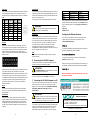
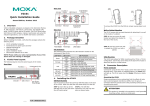
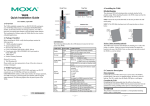
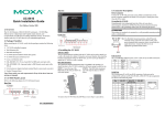
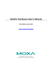
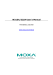
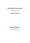
STEP 1: Insert the top of the DIN rail into the slot just below the stiff metal spring. Rear View UC-8481 Quick Installation Guide To remove the UC-8481 from the DIN rail, reverse steps 1 and 2 above. First Edition, May 2012 5. Connector Description 1. Overview The UC-8481 is an 802.11n, GPS, and 3G GSM/HSPA+ enabled embedded computer that comes with 2 RS-232/422/485 serial ports, 2 Ethernet ports, 4 digital input channels, 4 digital output channels, a CompactFlash socket, and 2 USB 2.0 ports, as well as a total of seven antenna ports to allow for easy expansion of Wi-Fi, cellular, and GPS capabilities. The UC-8481 is particularly well-suited for rolling stock or other vehicular applications, giving a solid, convenient foundation for constructing intelligent, cost-effective wireless communication platforms. 2. Package Checklist • • • • • • • STEP 2: The mounting assembly should then snap into place, as shown. 1 UC-8481 embedded computer Wall-mounting kit DIN rail mounting kit CBL-4PINDB9F-100: 4-pin pin header to DB9 female console port cable, 100 cm Quick installation guide (this guide) Document and software CD Warranty card Note: Please notify your sales representative if any of the above items are missing or damaged. 3. Panel Layout Refer to the following figures for the panel layouts. Front View Power Connector Connect the 24 VDC power line to the UC-8481’s power input with the M12 connector. When the OS has fully booted up, the Ready LED will glow a steady green color. LED Indicators The following table describes the LED indicators located on the front and rear panels of the UC-8481. LED Name Power LED Color Green Off Storage Yellow CF card is detected Off CF card is not detected Ready Green The system is ready Off The system is not ready X1 Green (programmable) Off LAN1, LAN2 P1 Tx, P2 Tx (on the right of the DB9 port) P1 Rx, P2 Rx (on the right of the DB9 port) LED Function Power is on and functioning normally Power is off, or power error Grounding the UC-8481 Grounding and wire routing help limit the effects of noise due to electromagnetic interference (EMI). Run the ground connection from the ground screw to the grounding surface prior to connecting the power. ATTENTION This product is intended to be mounted to a well-grounded mounting surface, such as a metal panel. There are two ground connectors on the front panel of the UC-8481. One is located at the middle pin of the power input, the other is beside the power input. Use either connector for grounding. Programmable: no default definition Programmable: no default definition Green Yellow 100 Mbps Ethernet mode 10 Mbps Ethernet mode Off No activity Green Off Serial port transmitting data Serial port not transmitting data Yellow Serial port receiving data Off Serial port not receiving data 4. Installing the UC-8481 Wall and cabinet mounts The two metal brackets included with the UC-8481 can be used to attach it to a wall or the inside of a cabinet. Using two screws per bracket, first attach the brackets to the bottom of the UC-8481. Next, use two screws per bracket to attach the UC-8481 to a wall or cabinet. SIM Card The UC-8481 comes with 3 cellular modules for wireless communication. Unscrew the SIM card cover and insert the SIM card in the desired slot. The SIM1 socket is reserved for the default cellular module. Ethernet Port The UC-8481 comes with 2 10/100 Mbps Ethernet ports with M12 connectors. DIN rail assemblies An aluminum DIN rail mounting assembly is included in the package. When attaching the rail assembly to the UC-8481, orient the stiff metal spring towards the top. P/N: 1802084800010 –1– –2– –3– Serial Port CompactFlash The 2 serial ports (P1 and P2) use DB9 male connectors. Each port can be configured by software for use on RS-232, RS-422, or RS-485 networks. The pin assignments are shown in the following table: The UC-8481 has a single CompactFlash type I/II slot for memory expansion, and comes with a single CompactFlash (CF) card. The CF card may be accessed by unscrewing the panel located on the bottom of the UC-8481 device. Pin RS-232 RS-422 The mount point for the CompactFlash filesystem is /mnt/sda. 1 2 3 4 5 6 7 8 TxDA(-) TxDB(+) RxDB(+) RxDA(-) GND – – – DCD RxD TxD DTR GND DSR RTS CTS RS-485 (4-wire) TxDA(-) TxDB(+) RxDB(+) RxDA(-) GND – – – RS-485 (2-wire) – – DataB(+) DataA(-) GND – – – Antenna The UC-8481 comes with its GPS, 3G GSM/HSPA+, and dual 802.11n antenna connectors already mounted by default; three more empty port-holes are provided, to be used when mounting antenna connectors for additional wireless, cellular or GPS modules. The following chart indicates the default configuration of antenna mounts: WARNING Be sure to power off the computer before inserting or removing the CompactFlash card! Console Port The RS-232 console port is a 4-pin header connector located on the underside of the motherboard above the CF card socket. As above, use a screwdriver to remove the panel protecting the CF card to access the 4-pin RS-232 connector. This serial port is used to access the console terminal, and is useful for viewing boot messages, file system logs, and error messages. Use the CBL-4PINDB9F-100 cable included with the UC-8481 to connect a PC to the UC-8481’s serial console port. USB The UC-8481 computer features 2 USB 2.0 ports for external storage expansion. 6. Powering on the UC-8481 Computer To power on the UC-8481, connect the power cable to the M12 connector and then connect the power adapter. ATTENTION Antenna connectors for the default 802.11n module are mounted on the W1 and W3 port-holes; connectors for the cellular GSM/GPRS/EDGE/UMTS/HSPA+ module uses the W5 port, and for the GPS module, on the W7 port. We strongly recommend that only qualified technical engineers for antenna installations, as this is a specific product that requires professional mounting and configuration. Please refer to the UC-8481 User’s Manual for detailed instructions. DI, DO The UC-8481 has 4 digital output channels and 4 digital input channels. T he UC-8481 User's Manual has detailed pinout and wiring diagrams. The Shielded Ground should be connected to the center pin of the power input connector. Note that it takes approximately 30 seconds for the system to boot up. Once the system is ready, the Ready LED will light up. Netmask DHCP 255.255.255.0 255.255.255.0 Note that LAN1 of the UC-8481 uses DHCP for both IP address and netmask. Once the UC-8481 is powered on and the Ready LED has lit up, a login page will open. The default Login and Password are root/root: Login: root Password: root Configuring the Ethernet Interface If you use the console cable for first-time configuration of the network settings, use the following commands to edit the /etc/network/interfaces file: #ifdown –a To reconfigure LAN settings all networking interfaces (LAN 1/eth0, LAN 2/eth1, WLANA/wlan0) must be disabled. #vi /etc/network/interfaces This command opens up the Vi editor to view and modify the interfaces configuration file. After the boot setting of the LAN interface has been modified, use the following command to activate the LAN settings immediately: #sync; ifup –a NOTE: For additional configuration information, refer to the UC-8481 User’s Manual. 7. Connecting the UC-8481 Computer to a PC There are two ways to connect the UC-8481 to a PC: through the serial console port, or by Telnet over the network. The COM settings for the serial console port are: Baudrate=115200 bps, Parity=None, Data bits=8, Stop bits =1, Flow Control=None. Reset Button ATTENTION Press and hold the “Reset” button continuously for at least 5 seconds to load the factory default configuration. After the factory default configuration has been loaded, the system will reboot automatically. The Ready LED will blink on and off for the first 5 seconds, and then maintain a steady glow once the system has rebooted. Remember to choose the “VT100” terminal type. Use the CBL-4PINDB9F-100 cable included with the product to connect a PC to the UC-8481’s serial console port. –4– Default IP Address DHCP 192.168.4.127 192.168.5.127 LAN 1 LAN 2 WLAN A To use telnet you will need to know the UC-8481’s IP address and netmask. The default LAN settings are shown below. For initial configuration, you may find it convenient to use a crossover Ethernet cable to connect directly from the PC to the UC-8481. –5– www.moxa.com/support The Americas: Europe: Asia-Pacific: China: +1-714-528-6777 (toll-free: 1-888-669-2872) +49-89-3 70 03 99-0 +886-2-8919-1230 +86-21-5258-9955 (toll-free: 800-820-5036) 2012 Moxa Inc., All Rights Reserved –6–