1
258
Chapter 10
Using Communication Function
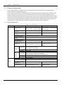
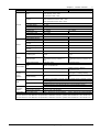
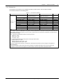
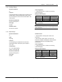
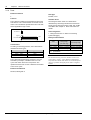
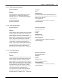
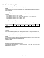
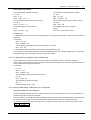
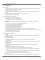
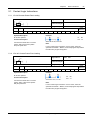
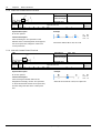
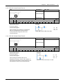
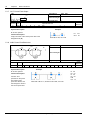
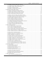
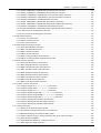
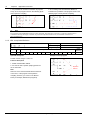
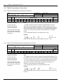
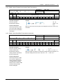
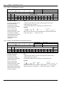
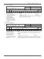
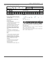
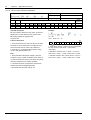
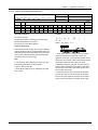
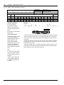
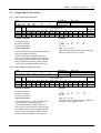
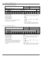
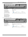
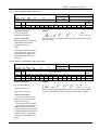
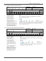
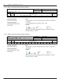
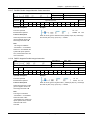
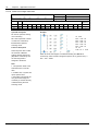
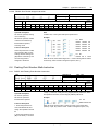
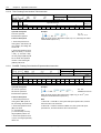
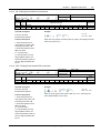
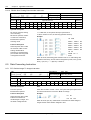
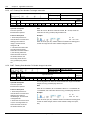
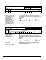
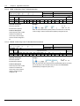
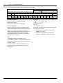
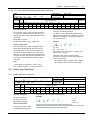
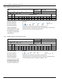
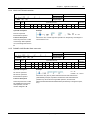
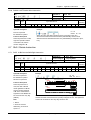
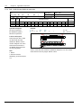
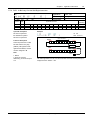
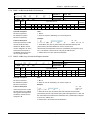
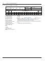
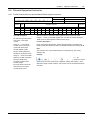
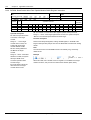
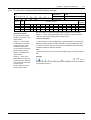
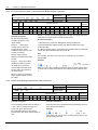
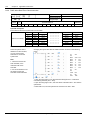
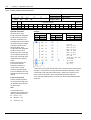
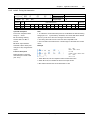
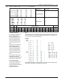
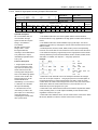
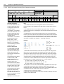
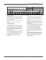
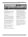
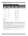
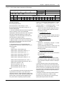
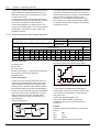
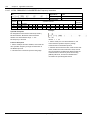
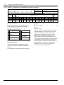
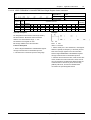
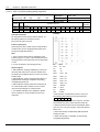
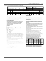
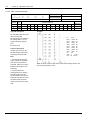
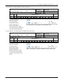
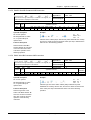
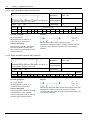
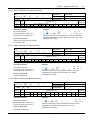
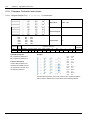
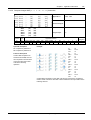
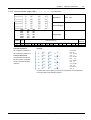
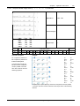
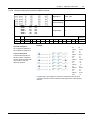
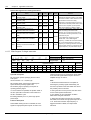
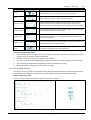
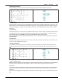
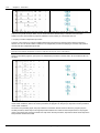
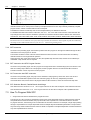
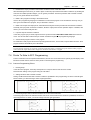
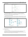
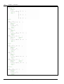
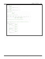
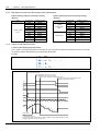
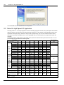
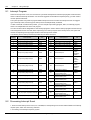
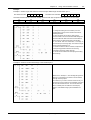
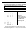
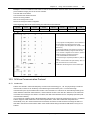
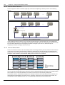
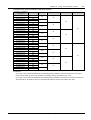
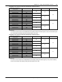
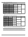
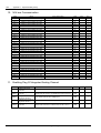
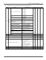
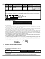
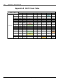
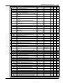
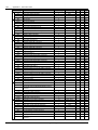
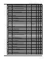
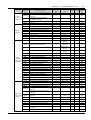
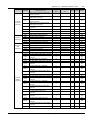
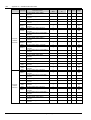
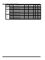
Distribution of M element on N:N bus single-layer network:
Distribution of M element
in sending area
M1400 to M1415
M1416 to M1431
M1432 to M1447
M1448 to M1463
M1464 to M1479
M1480 to M1495
M1496 to M1511
M1512 to M1527
M1528 to M1543
M1544 to M1559
M1560 to M1575
M1576 to M1591
M1592 to M1607
M1608 to M1623
M1624 to M1639
M1640 to M1655
M1656 to M1671
M1672 to M1687
M1688 to M1703
M1704 to M1719
M1720 to M1735
M1736 to M1751
M1752 to M1767
M1768 to M1783
M1784 to M1799
M1800 to M1815
M1816 to M1831
M1832 to M1847
M1848 to M1863
M1864 to M1879
M1880 to M1895
M1896 to M1911
Mode 1
#0
#1
#2
#3
#4
#5
#6
#7
#8
#9
#10
#11
#12
#13
#14
#15
#16
#17
#18
#19
#20
#21
#22
#23
#24
#25
#26
#27
#28
#29
#30
#31
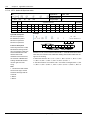
Mode 2
Mode 3
Mode 4
Mode 5
#0
#0
#1
#0
#2
#1
#0
#3
#4
#2
#5
#1
#6
#3
#0
#7
#8
#4
#9
#2
#10
#5
#11
#1
#12
#6
#13
#3
#14
#7
#15
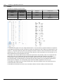
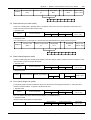
Explanation:
1) In mode 1, the M elements distributed to the sending area by 0# station range from M1400 to M1415. The
elements can be written by the PLC of 0# station and directly read by other stations (1#--31#).
2) In mode 2, the M elements distributed to the sending area by 0# station range from M1400 to M1431. The
elements can be written by the PLC of 0# station and directly read by other stations (1#--31#).
IVC Series Small PLC
Programming Manual