1
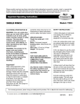
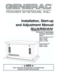
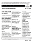
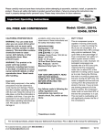
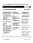
Please carefully read and save these instructions before attempting to assemble, maintain, install, or operate this
product. Observe all safety information to protect yourself and others. Failure to observe the instructions may
result in property damage and/or personal injury. Please keep instructions for future reference.
Important Operating Instructions
4000 XLT GENERATOR
CALIFORNIA PROPOSITION 65
WARNING: You can create dust
when you cut, sand, drill or
grind materials such as wood,
paint, metal, concrete, cement,
or other masonry. This dust
often contains chemicals
known to cause cancer, birth
defects, or other reproductive
harm. Wear protective gear.
WARNING: This product or its
power cord may contain
chemicals, including lead,
known to the State of California
to cause cancer and birth
defects or other reproductive
harm. Wash hands after
handling.
CAUTION:
FOR YOUR OWN SAFETY
READ INSTRUCTION MANUAL
COMPLETELY AND
CAREFULLY BEFORE
OPERATING THIS GASOLINE
ENGINE Failure to follow all
instructions as listed below
may result in electrical shock,
fire, and/or serious personal
injury.
Models: 9224, 52223
SPECIFICATIONS:
Engine: 4-stroke; Single phase;
Electronic ignition
Start Type:Recoil & Electric Start
Rated Power: 3500W
Fuel Capacity: 4gallons
Run Time:9 hours
SAFETY WARNINGS
1) Do not operate this generator
indoors or in enclosed spaces.
Emissions created by this
generator are harmful.
2) Do not operate the generator in
wet conditions. This will increase
the risk of electrical shock.
3) Do not directly connect the
generator to a household power
supply.
4) Do not smoke while refueling
the generator. Do not overflow the
fuel when refueling the generator.
Stop the generator before
refueling. Gasoline is
flammable and the sparks may
cause it to ignite. Keep the
generator at least 3 feet away
from flammable materials.
5) Electrical equipment,
including any lines and plug
connections, should be
insulated.
6) The circuit breakers should
be matched with the generator
equipment. If the circuit
breakers need replacement,
they must be replaced with a
breaker that has identical
ratings and performance
characteristics.
7) Do not operate the generator
before grounding it. An
ungrounded generator could
cause electrical shock to occur.
8) The temperature of the
environment will affect the
overcurrent protector. Please
change the protector so it will fit
with the local environment
temperature.
For warranty purchase, please keep your dated proof of purchase. File or attach to the manual for safekeeping.
For customer service, call 1-800-348-5004 or email [email protected]
1
8807517
12/7
9) Keep your work area clean
and well lit. Do not wear loose
clothing or jewelry. Keep long
hair pulled back.
10) Do not overload the
generator. Do not force a small
generator to do the job of a large
one.
11) Do not use the generator if
the power switch does not
properly turn it on and off.
12) Do not use damaged
generator.
13) Wipe up any gasoline spills
that may have occurred during
refueling before starting the
generator.
14) Do not refill the generator
while it is running or while the
engine is still hot.
15) Use only engine
manufacturer recommended fuel
and oil.
16) Do not attempt to connect or
disconnect load connections
while standing in water or on wet
or soggy ground.
Connect a #6 AWG groundingwire
(not included) from the generator
grounding log on the front of the
generator to a grounding rod (not
included) that has been driven at
least 24 inches into the earth. The
grounding rod must be an earthdriven copper or brass rod
(electrode) which can adequately
ground the generator.
3. Before the first use ,remove
the fuel Tank cap and fill the
Fuel Tank with unleaded
Pre-Start Checks:
gasoline . Then replace the fuel
1. Check to make sure the Engine Tank Cap. Thereafter, check the
Engine’s Fuel Gauge for the
Power Switch is in its "OFF"
amount of unleaded gasoline in
position. (See Figure C)
the Fuel Tank. If necessary, refill
2. IMPORTANT! Prior to first using the Fuel Tank with unleaded
the Generator , the Engine MUST gasoline; the Generator must be
turned off and cooled down
be filled with approximately 3/4
(0.63) quart of a high quality SAV before refilling the fuel tank.(See
Figure B.)
10W-30 grade engine oil. To do
so, unscrew and remove the
Engine’s Oil Dipstick located at the To Start The Engine
bottom of the Engine Crankcase.
1.Check to make sure the
Fill the Engine’s Crankcase until
the oil level is level with the upper Engine Switch is in its "OFF"
marked line on the Dipstick. Then, position.(See Figure C.)
screw the Dipstick back into the
Oil Fill Hole.(See Figure B.)
17) Keep all electrical equipment
clean and dry.
OPERATING
INSTRUCTIONS
FIGURE C
2.IMPORTANT: 2. Make sure to
unplug any load from the
Generator before starting to
prevent permanent damage to
any appliances, tools, or
equipment.
FIGURE A
GROUNDING THE
GENERATOR
[email protected]
FIGURE B
2
1-800-348-5004
3.Turn the Engine Fuel Valve to
its "ON" position. Then turn the
Engine Choke Lever to its
"CLOSE" position.
No choke is required if the
Engine is warm. Make sure the
Choke Lever is in the "OPEN"
position when starting a warm
Engine.(See Figure D.)
Then, pull the Starter Handle(See
Figure E.)with a rapid, full arm
stroke. Allow the Rope to rewind
slowly. If necessary, repeat this
procedure until the Engine starts.
3. CAUTION! Never exceed the
rated capacity for this Generator,
as serious damage to the
Generator and/or appliances,
tools, and equipment could result
from an overload. Starting and
running wattage requirements
should always be calculated
when matching this Generator’s
wattage capacity to the
appliance, tool, or equipment.
Figure E.
4.Use the DC12V terminals to
charge DC batteries.
WARNING! Frequently monitor
charging of DC batteries. Do not
overcharge.
6.When the Engine starts, slowly
move the Choke Lever to its
"OPEN" position. (See Figure D.)
Figure D
4.To start the Engine, using the
Battery (Model:9224 with
Battery, Model:52223 Battery not
included) for cranking power,
insert the Engine Switch Key into
the Engine Switch (See Figure
C.) Then turn the Key to the
"START" position. NOTE: To
prolong Starter life, use short
starting cycles (5 seconds
maximum). Then wait one
minute before attempting to start
again.
5.To start the Engine manually,
using the Starter Handle, insert
the Engine Switch Key and turn
the Key to its "RUN" position.
Grasp the Starter Handle, and
pull slowly until
resistance is felt. Allow the
Starter Rope to rewind slowly.
[email protected]
7.IMPORTANT:Allow the
Generator to run at no load for
five minutes after each start-up
so that the Engine and Generator
can stabilize.
TO CONNECT ELECTRICAL
LOADS
1.Start the Engine, and allow the
Engine and Generator to run and
warm up for five minutes after
starting with no electrical load.
2. WARNING! Connect 120 VAC
appliances, tools, and equipment
only to the two 120 VAC Outlet
Sockets. Connect 240 VAC
appliances, tools, and equipment
only to the one 240 VAC Outlet
Socket. (See Figure F.)
120/240V RECEPTACLE
120V RECEPTACLE
Figure F
3
5.Most appliances, tools, and
equipment will list on the motor
nameplate the starting and
running voltage and amperage
requirements. Use the following
formula to convert voltage and
amperage to wattage:
a.Volts x Amps = Watts
(example: 120 Volts x 3 Amps =
360 Watts)
b.To determine the approximate
wattage requirement for most
appliances, tools, and equipment
with "inductive" type motors,
multiply the wattage that was
calculated by 2 times to assure
adequate Generator capacity.
c.The starting and running
wattage for "resistant" loads are
the same. Example: a 100 watt
light bulb requires only 100 watts
to turn on. Most resistant loads
will be listed in wattage.
1-800-348-5004
6.Always power the largest
electric motor first. Then, plug in
other appliances, tools, and
equipment.
a.Connect "inductive" load
appliances, tools, and
equipment first. Inductive loads
consist of small hand tools and
some small appliances. Connect
the items that require the most
wattage first.
b.Connect any lights next.
c.Voltage sensitive appliances,
tools, and equipment should be
the last to be connected to the
Generator. Plug voltage
sensitive items such as T.V.’s,
VCR’s, microwaves, and
cordless telephones into a UL
Listed voltage surge protector
(not included). Then, connect
the surge protector into the
Generator.
7.IMPORTANT! Failure to
connect and operate appliances,
tools, and equipment in this
sequence can cause damage to
the Generator, appliances, tools,
and equipment and will void the
Warranty of this Generator.
8.Once the Engine is running,
simply connect the 120 VAC
appliances, tools, and
equipment into the 120 VAC
Outlet Sockets. Also, connect a
240 VAC appliance, tool, or
equipment into the 240 VAC
Outlet Socket .(See Figure F.)
[email protected]
9.NOTE:If Engine speed or
voltage fluctuates with a load
below 250 watts, move the
Engine Choke Lever to the
"HALF-CHOKE" position. (See
Figure D.)
NOTE: Do not allow the
generator to completely run
out of fuel with devices
attached. A generator’s output
may sharply spike as it runs
out of fuel, causing damage to
attached devices.
10.When finished using the
Generator, disconnect all
electrical loads. Turn the Engine
Switch to its "OFF" position to
stop the Engine. Then, close the
Engine Fuel Valve. (See Figures
C and D.)
11.Allow the Generator and its
Engine to completely cool. Then
store the unit in a clean, dry,
safe location out of reach of
children and other unauthorized
people
- a vacuum
- pressurized air
Never clean your generator with
a bucket of water or a hose.
Water can get inside the
working parts of the generator
and cause a short circuit or
corrosion.
Checking the Oil
The generator is equipped with
an automatic shutoff to protect it
from running on low oil.
Nonetheless, you should check
the oil level of the generator
before each use to ensure that
the generator crankcase has a
sufficient amount. To check the
oil level:
1. Make sure the generator is on
a level surface.
2. Unscrew the oil filler/dipstick
cap (see figure G).
3. With a dry cloth, wipe the oil
off of the stick on the inside of
the cap.
MAINTENANCE
Cleaning the Generator
Always try to use your generator
in a cool dry place. In the event
your generator becomes dirty
you may clean the exterior with
one or more of the following:
- a damp cloth
- a soft brush
4
4. Insert the dipstick as if you
were replacing the cap and then
remove again. There should
now be oil on the stick. If there
is no oil on the stick, or oil only
at the very end of the stick, you
should add oil until the engine
crankcase is filled. See
"Changing/ Adding Oil" in this
section.
1-800-348-5004
5. Be sure to reinstall the cap
when finished checking the oil
oil filler cap
Air Cleaner Maintenance
oil filler cap
Routine maintenance of the air
cleaner helps maintain proper
air flow to the carburetor.
Occasionally check that the air
cleaner is free of excessive dirt.
oil filler hole
Drain plug
Figure H
Figure G
Changing/ Adding Oil
You should check the oil level of
your generator.When the oil
level is low you will need to add
oil until the level is sufficient to
run the generator.
The oil capacity of your
generator engine is 37 fluid oz.
It is necessary to drain the oil
from the crankcase after 50 hrs
of use, or if it has become
contaminated with water or dirt.
In this case, you can drain the
oil from the generator according
to the following steps:
3. Replace the oil drain plug and
tighten with a hex wrench.
To add oil to the crankcase,
follow these steps:
1. Make sure the generator is on
a level surface.
2. Unscrew the oil filler/dipstick
cap from the engine as shown in
figure 12 above.
3. Using a funnel, add 30W, 4stroke engine oil. When full, the
oil level should come close to
the top of the oil fill opening (see
figure I).
[email protected]
2. Remove the sponge-like
elements from the casing.
3. Wipe the dirt from inside the
empty air cleaner casing.
4. Wash the sponge-like
elements in household
detergent and warm water.
Allow to dry.
5. Soak the dry elements in
engine oil. Squeeze out any
excess oil.
6. Replace the sponge-like
elements in the air cleaner
casing and replace the cover.
ELEMENT
1. Place a bucket underneath
the generator to catch oil as it
drains.
2. Using a hex wrench, unscrew
the oil drain plug, which is
located on the crankcase
underneath the oil filler/dipstick
cap (see figure H). Allow all the
oil to drain from the generator.
1. Unscrew the four bolts at the
top and bottom of the air cleaner
cover (see figure J).
Figure I
NOTE: Never dispose of used
motor oil in the trash or down a
drain. Please call your local
recycling center or auto garage
to arrange oil disposal.
5
Figure J
1-800-348-5004
Fuel Filter Cup Cleaning
The fuel filter cup is a small well
underneath the fuel valve. It
helps to trap dirt and water that
may be in your fuel tank before
it can enter the engine. To clean
the fuel filter cup.
1. Turn the fuel valve to the "off"
position.
2. Unscrew the fuel filter cup
from the fuel valve using a
wrench. Turn the valve toward
you to unscrew (see figure K).
3. Clean the cup of all sediment
using a rag or brush.
Visually inspect the spark plug.
If it is cracked or chipped,
discard and replace with a new
spark plug. Measure the plug
gap with a gauge (see figure M).
The gap should be (0.0280.031in.).
3. If you are re-using the spark
plug, use a wire brush to clean
any dirt from around the spark
plug base and then re-gap the
spark plug.
4. Screw the spark plug back
into its place on the generator
using the spark plug wrench.
Replace the spark plug cap.
1. Turn the fuel valve to the "off"
position.
2. Remove the fuel filter cup
(see "Fuel Filter Cup Cleaning"
earlier in this section).
3. Empty the fuel filter cup of
any fuel.
4. With a receptacle underneath
the generator to catch the gas,
turn the fuel valve to the "on"
position. Drain all the gas from
the generator.
5. Turn the fuel valve to the "off"
position.
6. Replace the fuel filter cup.
4. Reinstall the fuel filter cup.
Figure L
7. Store the emptied gasoline in
a suitable place.drain. Please
call your local recycling center
or auto garage to arrange oil
disposal.
Figure K
Spark Plug Maintenance
The spark plug is important for
proper engine operation. A
good spark plug should be
intact, free of deposits, and
properly gapped. To inspect
your spark plug:
Figure M
Emptying the Gas Tank
1. Pull on the spark plug cap to
remove it.
2. Unscrew the spark plug from
the generator using the spark
plug wrench included with this
product (see figure L).
[email protected]
Before storing your generator for
extended periods of time, you
should drain your generator of
gasoline. To drain the generator
of gas:
6
1-800-348-5004
Recommended Maintenance Schedule
first month of
each use
Engine oil
check level
check
50 hrs
x
x
gas tank
check gas level
As
or 300 hrs necessary
x
x
x
x
x
Clean
[email protected]
100 hrs
every year
x
fuel filter cup Clean
check/ clean
months or months or
hrs
Clean
spark plug
every 6
x
Replace
Air cleaner
use or first 20
every 3
x
7
1-800-348-5004
Troubleshooting Guide
[email protected]
8
1-800-348-5004
Limited Manufacturer Warranty
North American Tool (NAT) Industries makes every effort to ensure that this product meets high quality
and durability standards. NAT warrants to the original retail consumer a 1-year limited warranty from
the date the product was purchased at retail and each product is free from defects in materials.
Warranty does not apply to defects due directly or indirectly to misuse, abuse, negligence or accidents,
repairs or alterations, or a lack of maintenance. NAT shall in no event be liable for death, injuries to
persons or property, or for incidental, special or consequential damages arising from the use of our
products. To receive service under warranty, the original manufacturer part must be returned for
examination by an authorized service center. Shipping and handling charges may apply. If a defect is
found, NAT will either repair or replace the product at its discretion.
DO NOT RETURN TO STORE
For Customer Service:
Email: [email protected] or Call 1-800-348-5004
[email protected]
9
1-800-348-5004
4000 XLT GENERATOR
Models: 9224, 52223
Parts List - Generator
For customer service, call 1-800-348-5004 or email [email protected]
10
8807517
12/7
Parts List
Call 1-800-348-5004 for assistance or replacement parts
Please provide the following information
-Model number
-Part description and number as shown in parts list
-Serial number
Address any correspondence to:
North American Tool Industries
84 Commercial Rd
Huntington, IN 46750
[email protected]
1-800-348-5004
11
4000 XLT GENERATOR
Models: 9224, 52223
Parts List - Engine
For customer service, call 1-800-348-5004 or email [email protected]
12
8807517
12/7
Parts List
Call 1-800-348-5004 for assistance or replacement parts
Please provide the following information
Address any correspondence to:
-Model number
North American Tool Industries
84 Commercial Rd
Huntington, IN 46750
-Part description and number as shown in parts list
-Serial number
No.
1
2
3
4
5
6
7
8
9
10
11
12
13
14
15
16
17
18
19
20
21
22
23
24
25
26
27
28
29
30
31
32
33
34
35
36
37
38
39
40
41
42
43
44
45
46
Spare parts code
2.55.07.001000
2.55.06.000100
2.55.05.005206
2.55.05.005201
2.55.05.005205
/
2.54.02.000200
2.54.02.000300
2.54.04.000100
2.63.01.00274
2.63.01.00340
2.51.03.000100
2.54.03.000100
2.63.01.00170
2.63.01.00092
/
2.63.01.00370
/
/
/
/
2.51.10.000100
/
/
2.52.06.000100
2.63.01.00045
2.53.05.000200
/
2.63.01.00278
2.52.03.000100
2.52.04.000200
2.53.01.000100
2.52.07.000100
2.51.17.000100
2.63.01.00173
2.51.04.000700
2.63.01.00178
2.63.01.00149
/
2.63.02.006000
2.51.04.000100
2.51.02.000100
2.50.05.000104
2.50.05.000103
2.50.06.000100
2.50.07.000100
Name
CLIP TUBE
TUBE FUEL
JOINT ASSY FUEL TANK
CAP COMP FUEL FILLER
FILTER FUEL
TANK COMP FUEL
SPRING THROTTLE
SPRING THROTTLE
ARM GOVERNOR
NUT FLANGE
PIN LOCK
SHAFT GOVERNOR ARM
ROD GOVERRNOR
BOLT FLANGE
BOLT QUADRATE HEAD
CONTROL ASSY
WASHER PAIN
COVER COMP FAN
OIL STICK
CONNECTING ROD
PIN PISTON
CLIP PISTON PIN
PISTON
RING SET
SHROUD
BOLT STUD EXHAUST
SWITCH ASSY ENGINE
COVER COMP FAN
NUT SPECIAL
PULLEY STARTER
FAN COOLING
FLYWHEEL COMP
DIVERSION ASSY
OIL SEAL25*41.25*6
BOLT FLANGE
ALART UNIT OIL
BOLT FLANGE
BOLT DRAIN PLUG
CRANK CASE
BEARING RADIAL BALL
OIL LEVEL SWITCH
GEAR GOVERNOR
ARM VALVE ROCKER
BOLT PIVOT ARM
PLATE ASSY
ROD PUSH
Qty No. Spare parts code
2
47 2.63.01.01036
1
48 /
1
49 /
1
50 2.60.01.001100
1
51 /
1
52 2.60.03.000100
1
53 2.51.05.000800
1
54 2.63.01.00208
1
55 2.63.01.00166
5
56 /
1
57 2.50.04.000100
1
58 /
1
59 /
9
60 2.63.01.00404
1
61 2.50.05.000101
1
62 2.50.05.000102
1
63 2.63.01.00181
1
64 2.53.02.000100
1
65 2.63.01.00406
1
66 2.63.01.00256
1
67 2.60.05.000100
2
68 2.55.01.000601
1
69 /
1
70 2.60.04.000100
1
71 2.55.02.000100
2
72 2.60.02.000100
1
73 2.63.01.00051
1
74 2.63.01.00365
1
75 /
1
76 2.60.09.000100
1
77 2.50.09.001300
1
78 2.50.09.000200
1
79 2.50.09.000300
2
80 2.50.09.000100
4
81 2.53.06.000200
1
82 /
1
83 /
2
84 2.50.03.000100
1
85 2.63.01.00270
2
86 2.63.01.00182
1
87 2.63.01.00175
1
88 2.63.01.00497
2
89 2.62.01.000100
2
90 2.50.10.000100
1
91 /
2
92 2.62.01.000600
[email protected]
13
Name
KEY SPECIAL WOODRUFF
MUFFLER ASSY
CRANKSHAFT COMP
PACKING CASE COVER
OIL FILLER CAP
GASKET MUFFLER
COVER
BOLT, M8*32
BOLT, M6*10
AIR CLEANER
VALVE EX
LEFTER VALVE
CAMSHAFT ASSY
PIN FLYING BLOCK
PIVOT ROCKER ARM
NUT PIVOT ADJUSTING
BOLT FLANGE 6*25
COIL ASSY IGNITION
PIN DOWER
BOLT FLANGE 8*55
SPACER COMP AIR
CHOKE HANDLE
CARBURETOR
PACKING CABURETOR
INSULATOR, CARBURETOR
PACKING INSUL ATOR
BOLT STUD IN
WASHER,8
COVER COMP HEAD
PACKING HEAD COVER
RATATOR VALVE
SEAL GUIDE
RETAINER VALVE SPRING
SPRING VALVE
PLUG SPARK
HEAD COMP CYLINDER
GASKET CYLINDER
VALVE IN
NUT HEX 8MM
BOLT, M6*28
BOLT, M6*16
WASHER DRAIN PLUG
WIRE CLIP
SEAL GUIDE
PING
Bushing
8807517
Qty
1
1
1
1
1
1
1
6
3
1
1
2
1
2
2
2
2
1
2
4
1
1
1
1
1
1
2
2
1
1
1
1
1
2
1
1
1
1
2
1
2
2
1
1
1
1
12/7
Wire Diagram
[email protected]
AC 240V /120V
CIRCUIT BREAKER
AV120V
VOLT MERTER
V
R E C T I F I ER
ON
OFF
ENGINE
SWITCH
BREAKER
DC12V OUTPUT
CIRCUIT BREAKER
RED
GREEN
F+
F-
Oil Level
Switch
AVR
VOLT
ADJSUT
8807517
Generator Block
START MOTOR
BLACK
CHARGE
RELAY
YELLOW
BATTERY
14
FUSE
Ignition Coil
ENGINE Block
12/7