1
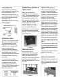
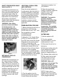
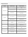
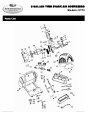
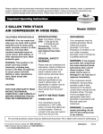
2 GALLON TWIN STACK
AIR COMPRESSOR
CALIFORNIA PROPOSITION 65
WARNING: You can create dust
when you cut, sand, drill or grind
materials such as wood, paint,
metal, concrete, cement, or other
masonry. This dust often
contains chemicals known to
cause cancer, birth defects, or
other reproductive harm. Wear
protective gear.
WARNING: This product or its
power cord may contain
chemicals, including lead,
known to the State of California
to cause cancer and birth
defects or other reproductive
harm. Wash hands after
handling.
CAUTION:
FOR YOUR OWN SAFETY READ
INSTRUCTION MANUAL
COMPLETELY AND CAREFULLY
BEFORE OPERATING THIS OILFREE AIR COMPRESSOR KIT.
SPECIFICATIONS
Type: Twin Stack, Oil free
CFM: 1 CFM @ 40 PSI
.5 CFM @ 90 PSI
Horsepower: 1/4 HP
Maximum PSI: 100 PSI
GENERAL SAFETY
WARNING
Please read and understand all
instructions. Failure to follow all
instructions listed below may
result in electric shock, fire
and/or serious personal injury.
Failure to comply with all
electrical specifications may
result in serious injury. All
adjustments or repairs must be
done with the compressor
disconnected from the power
source.
SAFETY INSTRUCTIONS
POWER SUPPLY
Your compressor must be
connected to a 120V outlet,
using a 15-amp time delay fuse
or circuit breaker. Failure to
connect in this way can result in
injury from shock or fire.
For Customer Service, call 1-800-348-5004 or email [email protected]
Model: 51735
GROUNDING
Your compressor must be
properly grounded. Not all
outlets are properly
grounded. If you have
hesitations on whether or not
your outlet is properly
grounded, have it checked by
a qualified electrician.
WARNING: If not properly
grounded, this compressor
can cause electrical shock,
particularly when used in
damp locations. If the
power cord is worn or
damaged in any way have it
replaced immediately.
If the compressor should
breakdown, the grounding
provides a path of least
resistance for the electric
current which reduces the risk
of electric shock. The plug
must be plugged into an
appropriate outlet that is
grounded in accordance with
the local codes and
ordinances.
WARNING: To maintain
proper grounding, do not
alter the grounding prong
in any manner.
88051735
07/10
120V OPERATION
OPERATION CONTROLS
REGULATOR (A) FIG. 4
As received from the factory,
your compressor is ready to run
for 120V operation. This
machine is intended for use on
a circuit that has an outlet and a
plug which looks like the one
illustrated in Fig.1.
CHECK VALVE
The air pressure coming from the
air tank is controlled by the
regulator. Turn the regulator knob
clockwise to increase pressure and
counterclockwise to decrease
pressure. To avoid minor
readjustment after making a
change in the pressure setting,
always approach the desired
pressure from a lower pressure.
When reducing from a higher to a
lower setting, first reduce the
pressure less than that desired,
then bring it up to the desired
pressure. Depending on the air
requirements of each particular
accessory, the outlet regulated air
pressure may have to be adjusted
while operating the accessory.
WARNING: Do not use a twoprong adapter.
When the compressor is
operating, the check valve is
“open”, allowing compressed air
to enter the air tank. When the
air compressor reaches “CutOut” pressure, the check valve
“closes”, allowing air pressure to
remain inside the air tank.
ON/OFF SWITCH (A) FIG. 3
Turn this switch ON (press
downwards) to provide power to
the automatic pressure switch
and OFF to remove power at the
end of each use.
EXTENSION CORDS
The use of any extension cord
will cause some loss of power.
It is recommended to use a
longer air hose instead of an
extension cord. Use the chart
below to determine the
minimum wire size extension
cord. Use only 3-wire extension
cords which have 3-prong
grounding type plugs and 3-hole
receptacles which accept the
tool’s plug.
For circuits that are further
away from the electrical circuit
box, the wire size must be
increased proportionately in
order to deliver ample voltage to
the motor. Refer to Fig. 2 for
wire length and size.
[email protected]
OUTLET PRESSURE GUAGE (B)
FIG. 4
The tank pressure gauge indicates
the reserve air pressure in the tank.
PRESSURE SWITCH
The pressure switch
automatically starts the motor
when the tank pressure drips
below the factory set “Cut-in”
pressure. It also stops the motor
when the air tank pressure
reaches the factory set “Cut-Out”
pressure.
2
TANK PRESSURE GAUGE (C)
FIG. 5
Indicates the available reserve air
pressure in the tank.
DRAIN VALVE (A) FIG.5
The drain valve is located on the
base of the air tank and is used to
drain condensation at the end of
each use.
SAFETY PRESSURE RELEASE
VALVE (A) FIG. 6
ADDITIONAL REGULATORS
AND CONTROLS
tank pressure reaches “cutout” pressure.
If the pressure switch does not
shut off the air compressor at its
cutout pressure setting and the
air pressure keeps rising, the
safety valve will protect against
high pressure by “popping out”
above factory set pressure
(slightly higher than the pressure
switch cut-out setting).
Since the air tank pressure is
usually greater than that which is
needed, a regulator is employed
to control the air pressure ahead
of any individual driven device.
Separate air transformers which
combine the function of air
regulation, moisture and dirt
removal should be used where
applicable.
6) Open the regulator by
turning it clockwise. Adjust the
regulator to the correct
pressure setting. The
compressor is ready.
WARNING: If the safety
pressure release valve does
not work properly, over
pressurization may occur,
causing air tank to rupture or
explode. Pull the ring on the
safety valve daily to make sure
that the safety valve operates
freely. If the valve is stuck or
does not operate smoothly, it
must be replaced with the
same type of valve.
SETTING UP YOUR AIR
COMPRESSOR
Operate the air compressor in a
dry, clean and well ventilated
area. Clean off dust or dirt that
collects on the air compressor. A
clean air compressor runs cooler
and provides longer service. The
ventilation openings on your air
compressor are necessary to
maintain proper operating
temperature. Do not place rags
or other containers near these
openings.
[email protected]
PREPARATION FOR USE
1) Before attaching the air hose or
accessories, make sure the
On/Off switch is set to “OFF” and
the air regulator is closed
(completely turned
counterclockwise).
2) Attach the 1/4in. female fitting
(A Fig.7) to one end of the coil
hose (B), then connect the female
fitting (A) into the quick connect
outlet (C) at the back of the
compressor, then attach the 1/4in.
female quick connect (D) to the
other end of the coil hose. Attach
optional air tool or supplied
accessories. To prevent air leaks,
it is recommended to install Teflon
Tape (not supplied) on the threads
at both ends of the coil hose.
WARNING: Too much air
pressure causes a
hazardous risk of bursting.
Check the manufacturer’s
maximum pressure rating
for air tools and
accessories. The regulator
outlet pressure must never
exceed the maximum
pressure rating of the tool
being used.
AFTER USE
1) Set the switch to Off.
2) Turn the regulator
counterclockwise to set the
outlet pressure to zero.
3) Disconnect the air tool or
accessory.
4) Pull ring on safety valve (A)
Fig.6, allowing air to bleed
from the tank until tank
pressure is approximately 20
PSI. Release safety valve ring.
5) Drain water from air tank.
Turn drain valve (A) Fig. 5
counterclockwise to open.
WARNING: Water will
condense in the air tank. The
water will corrode and
weaken the air tank causing
a risk of air tank rupture if it
is not drained properly.
5) Turn the switch to the On
position and allow tank pressure
to build. Motor will stop when
3
NOTE: If drain valve is
plugged, pull ring on safety
valve (A) Fig.6, and hold until
all air pressure has been
released. The drain valve can
then be removed, cleaned, and
reinstalled.
6. After the water has been
completely drained, turn the drain
valve to close. The air compressor
can now be stored.
MAINTENANCE
Before doing any maintenance or
adjustments to your air
compressor, the following safety
precautions should be taken:
REPLACEMENT PARTS
For servicing, contact or return to
the retailer where you purchased
your product along with your proof
of purchase. Please use the 10digit part numbers listed in this
manual for all part orders where
applicable.
- Disconnect electrical power.
- Release air tank pressure.
DAILY OR BEFORE EACH USE
1) Drain condensation from tank.
2) Check for unusual noise or
vibration.
3) Be sure all nuts and bolts are
tight.
KEEP TOOL CLEAN
Periodically blow out all air
passages with dry compressed
air. Clean all plastic parts with a
soft damp cloth. NEVER use
solvents to clean plastic parts.
This could possibly dissolve or
otherwise damage the material.
CAUTION: Wear safety glasses
while using compressed air.
FAILURE TO START
Should your compressor fail to
start, check to make sure the
prongs on the cord plug are
making good contact with the
outlet. Also, check compressor
fuse or tripped circuit breakers in
the line.
[email protected]
4
Symptom
No start condition
Possible Cause(s)
Corrective Action
Fuse blown or circuit breaker tripped
Check for cause of blown fuse/breaker and
replace
loose electrical connections
Check wiring connections
Overheated motor
Turn compressor off, wait until total cool down
before restarting
Air leak in safety valve
Check valve manually by pulling upwards on
ring. If condition persists, replace valve
Defective check valve
Replace check valve
Defective pressure switch or improper
adjustment
Check for proper adjustment and if problem
persists, replace pressure switch
Loose drain valve
Tighten drain value
Loose connections at regulator or
pressure switch
Check connections for leaks, seal with teflon
tape
Excessive water in tank
Drain tank through drain valve
Humidity too high
Move compressor to an area of less humidity.
Low pressure
Safety valve releasing
Tamk pressure drops when
compressor is shut off
Excessive moisture coming
out of air hose
[email protected]
5
North American Tool (NAT) Industries makes every effort to ensure that this product meets high
quality and durability standards. NAT warrants to the original retail consumer a 1-year limited warranty
from the date the product was purchased at retail and each product is free from defects in materials.
Warranty does not apply to defects due directly or indirectly to misuse, abuse, negligence or
accidents, repairs or alterations, or a lack of maintenance. NAT shall in no event be liable for death,
injuries to persons or property, or for incidental, special or consequential damages arising from the
use of our products. To receive service under warranty, the original manufacturer part must be
returned for examination by an authorized service center. Shipping and handling charges may apply. If
a defect is found, NAT will either repair or replace the product at its discretion.
[email protected]
6
2 GALLON TWIN STACK AIR COMPRESSOR
Models: 51735
For Customer Service, call 1-800-348-5004 or email [email protected]
89051735
07/10
#
1
2
3
4
5
6
7
8
9
10
11
12
13
14
15
16
17
18
19
20
21
22
23
24
25
26
27
28
29
30
31
32
33
34
Description
Bolt M5x55
Spring Washer M5
Cylinder Head
Support of Cylinder Head
Gasket of Cylinder Head
Inlet Valve Reed
Cover of Valve Reed
Plug of Exhaust
O-Ring of Plug
Inlet Spring
Gasket for Exhausting
Cylinder
Eccentric
Screw M6x15
Conrod
Bearing of Conrod
Cover of Conrod
Piston Ring
Crankcase
Axle
Bearing of Crankcase
Screw M5x10
Washer M5
Driven Gear
Active Gear
Motor
Screw M3x30
Spring Washer M3
Fan
Cover of Motor
Circlip M6
Exhaust Elbow
Regulator Manifold
Safety Valve
[email protected]
QTY
#
3
3
1
1
1
1
1
1
1
1
1
1
1
1
1
1
1
1
1
1
1
1
1
1
1
1
2
2
1
1
1
1
1
1
35
36
37
38
39
40
41
42
43
44
45
46
47
48
49
50
51
52
53
54
55
56
57
58
59
60
61
62
63
64
65
66
67
68
2
Description
Y50 Pressure Gauge
Y40 Pressure Gauge
Quick Coupler
Cushion
Washer M5
Screw M5x20
Power Cord
Shroud
Electric Switch
Exhaust Tube
Rubber Hose
Pressure Switch
2 Gal Twin Tank
Drain Valve
Connect of Check Valve
Spring of Check Valve
Seal Gasket of Check Valve
Support Rubber
Support Bolt
Nut M6
Spring Washer M6
Tapping Screw
Screw M4x6
Washer M4
Screw M6x25
Control Panel of Manifold
Screw M4x10
Dual End Cord
Single End Cord
R Type Wrap
Cable Connector
Cap Press for Cord
Grounding Signal
Tool Box