1
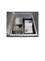
DESIGNED BY EXPERIENCE
PLASTIC SPHERE DISPENSER
USER MANUAL
Manufactured by PSDS, Inc. for sole distribution by:
AEROSTAT, INC.
8830 AIRPORT BLVD
LEESBURG, FL 34788
WEBSITE: AEROSTATINC.COM
TEL: 352 787-1348
FAX: 352 787-4666
MADE IN THE USA
WARNING!
Please review the following before
using your MARK V Dispenser.
• Keep all moving parts of the dispenser well lubricated
•
•
•
•
•
•
•
(lubricant should be applied before each use).
Bench test dispenser per instructions before use in the field.
Do not leave balls in the dispenser when the machine is not
in use.
Clean glycol and water filler strainers often.
Make sure safety harness strap is properly secured before
using machine.
Clean machine after using and before storing it for prolonged
periods of time.
Do not store or transport the dispenser without first draining
all fluids
If dispenser does not function properly contact Aerostat, Inc.
for assistance (Telephone: 352 787-1348).
Serial Number: _____________________
2
USING YOUR MARK V PLASTIC SPHERE DISPENSER
Your MARK V plastic sphere dispenser (PSD) has been designed for longevity as well as
for ease of operation. While similar in shape to some other dispensers the MARK V has
a number of enhancements that will make the users life much easier while increasing the
dependability of the machine over any other dispenser currently on the market.
Your MARK V PSD comes with an unprecedented twenty-four month warranty from
date of shipping to you. This warranty exceeds any other manufacturers warranty and
provides you with the assurance that should you have any problems with your MARK V
dispenser under normal use* it will be repaired at no cost to you for materials or labor.
Users should familiarize themselves with the operating instruction contained in this
manual before actually using the machine. Failure to do so could result in the improper
use of the dispenser and thus void your warranty.
*If the machine is damaged through improper use or abuse (i.e., failure to keep the machine properly
lubricated or dropping the machine) it will void the warranty.
3
INDEX
Removal of Dispenser from Transit Case ………………………
5
Testing the Dispenser …………………………………………...
7
Priming and Adjusting the Manifold …………………………… 10
Bench Testing the Dispenser ……………………………………. 12
Using the MARK V Plastic Sphere Dispenser ………………….. 14
Storing the Dispenser ………………………………………….…. 16
Troubleshooting the Dispenser …………………………………... 17
Appendix 1 – Dispenser Specifications ………………………….. 19
Appendix 2 – Repairs, Updates and Parts ………………………... 20
Appendix 3 – User Maintenance of the MARK V ……………….. 21
4
REMOVAL OF DISPENSER FROM ITS TRANSIT CASE
1. Open the transit case for your MARK V PSD by lifting the latch located in the
middle of the front of the transit case immediately below the lid.
2. If this is the first time the PSD is being removed from the case carefully remove
any packing around the dispenser.
3. There are six components of the PSD in the transit case. See figure 1 on the next
page..
4. Remove the drop chute extension from the case and set it aside.
5. Remove the mainframe and attached water tank of the machine by slipping the
fingers of one hand around the manifold and grasping the handle on the back of
the mainframe with the other. Lift the machine straight up and out of the case and
place it down carefully on a sturdy surface.
6. Under the mainframe is a stabilization tray which can be used to stabilize the
MARK V depending on the helicopter you will be using the machine in.
7. Remove the hopper from the case by grasping the handle on the top of the feeder
chute and the handle on the back of the hopper. Lift the hopper straight up and
out of the transit case. Place the hopper on top of the mainframe. (The feeder
chute should face the manifold.) Be sure to align the slots in the side of the feeder
chute with the guides sticking up inside the mainframe.
8. Remove the harness from inside the hopper. Secure the clips on the harness to the
“D” rings located on each side of the mainframe. The end of the harness will be
fastened to the buckle on the short strap which is mounted on the handle on the
back of the mainframe when the dispenser is installed for use in the helicopter.
5
Figure 1
6
Testing the Dispenser
[NOTE: Refer to Figure 2 to identify the location of any component.]
LID
HOPPER
HOPPER CONTROL
FEED CHUTES
WATER TANK
MAINFRAME
MANIFOLD
MAIN CONTROL
PANEL
MANUAL
ASSIST WHEEL
Figure 2
Initial Check of the Dispenser
1. Remove the hopper from the top of the mainframe to expose the filler caps for
both the water and glycol tanks.
2. Lift water tank up from the mainframe (about 2 to 3 inches) and remove water
line hose from brass fitting on the bottom of the tank. Set tank aside.
3. Unscrew the two wing nuts on the sides of the mainframe to remove mainframe
cover. Visually check that all hoses are properly connected.
4. Insert water line through slot in the middle of the cover and then replace cover
and retighten wing nuts. [NOTE: Be sure washers are between the outside edge of
the cover and the wing nuts.]
5. Open the water tank and check the strainer in the filler neck. Clean out any debris
that may be in it.
7
6. Push water line on to the brass fitting on the bottom of the water tank and set the
water tank into the four guide holes on the top of the mainframe cover.
7. Fill water tank with water and replace cap.
8. Open the cap on the glycol tank. Clean out any debris that may be in the strainer.
9. Fill glycol tank with clean ethylene-glycol (aka: antifreeze). Be careful not to
overfill tank. In the event of an overfill wipe up all excess glycol being careful
not to push any dirt into the tank.
10. Replace the cap on the glycol tank.
11. Install hopper on to the top of the mainframe being careful to align the grooves in
the hopper feeder chute with the guides inside the mainframe. [NOTE: When
properly positioned the top of the hopper should be parallel with the top of the
mainframe.]
12. Connect the wire lead from the hopper to the “two prong” male plug on the back
of the mainframe.
13. Connect a 24-28vdc power source to the wire coming out of the back of the
mainframe. [NOTE: The PSDS power supply can simply be plugged into the
plug on the rear of the mainframe.]
14. Turn on the motor switch (green LED should light) on the mainframe and observe
the direction of rotation of the manual assist wheel on the side of the mainframe.
Rotation should be in the direction of the arrow on the wheel. If it is not the lines
from the power source need to be reversed.
15. Turn on the hopper control panel switch (the LED indicator should light) and
observe that the shuffle plate in the hopper moves back and forth.
16. Turn off the hopper control switch.
17. Move the speed control switch on the main electrical panel into its opposite
position and observe a change in the speed of the slipper blocks.
18. Familiarize yourself with the next section of this manual, Priming and Adjusting
the Manifold.
19. Turn on the glycol pump control switch on the side of the mainframe. The amber
LED should illuminate and you should be able to hear the pump running.
20. Prime the manifold per the instructions in the Priming and Adjusting the Manifold
section of the manual.
8
21. Turn off the glycol pump switch.
22. Depress the emergency water switch button. The red LED should illuminate and
you should hear the pump run. Hold the switch button in until you see water
coming from the four holes in the manifold. [NOTE: There is no need to prime
the water pump.]
23. Release the emergency water switch button.
24. Disconnect the 24-28vdc power source from the dispenser.
9
Priming and Adjusting the Manifold
Needle Valve Adjustment Manifold
This manifold is similar to the manifolds used in older PSD machines. However, its
advanced design allows for ease of both priming and adjusting the flow of glycol per the
following directions.
Lubricate all four plungers with a water proof lubricant where the plunger depresses into
the manifold before use.
Connect the PSD to a power source and turn on the glycol pump (NOTE: The motor must
be in the on position for the glycol pump to work.) Open the bleeder screw (about one
turn) located in the brass plug on the side of the manifold using a Phillips screw driver.
When glycol starts to escape from the bleeder screw in a steady stream the manifold is
primed and the screw should be retightened. (Note: See figure 3 – bleeder screw can be
seen protruding from the brass fitting on the left.)
Figure 3
10
The flow of glycol is adjusted as follows (the procedure must be followed for each of the
four needles):
• Loosen the locking nut all the way.
• Turn the needle valve in a clockwise direction until it bottoms out.
• Turn the needle valve no more than ONE QUARTER TURN in a
counterclockwise direction. There are orientation marks on both the manifold and
the needle valve. The needle valve orientation mark should be located between
the two marks on the manifold when properly adjusted (see Figure 4).
Figure 4
•
•
•
Hold the needle valve to be sure it does not move while tightening down the
locking nut securely.
While holding out the manual assist wheel depress the plunger on the manifold
for each needle to observe that the flow from each needle is the same. (Proper
priming of a sphere requires about .75 cc of glycol.)
If additional glycol flow is desired (i.e., using the machine in cold temperatures)
the needle valve can be opened further but be careful not to over prime the
spheres may melt instead of igniting.
11
Bench Testing the Dispenser
[NOTE: This test should not be done until having first performed the “Initial Check of
the Dispenser” as described above. Before beginning this test make sure the machine is
located in an area that is well vented. It is strongly recommended that this operation be
performed outside any building.]
1. Carefully secure the PSD on a bench with the short chute extending over the edge.
[NOTE: The machine must be secured to the bench in order to be certain that it
does not tip forward and fall when you start testing.]
2. Place a metal container below the short chute to catch balls. [NOTE: Container
should be tall enough so that the balls will not bounce out when dropped into it.]
3. Check the glycol and water tanks to make sure there is glycol and water in the
respective tanks and that the glycol pump is primed.
4. Check that the hopper is securely mounted on the mainframe and that the
electrical connection is properly secured.
5. Verify that the hopper control handles are in the down position to prevent any
spheres from leaving the hopper.
6. Place some live aerial ignition spheres into the hopper and observe that the four
chutes leading from the hopper fill with spheres.
7. Connect a 24-28vdc power source to the leads coming out of the back of the
mainframe.
8. Turn on the motor switch on the mainframe electrical control box and observe the
direction of rotation of the manual assist wheel. If the wheel is not rotating in the
direction of the arrow shut off the motor and reverse the leads from the 24-28vdc
power source from the way they are connected. Re-start the motor and verify that
the manual assist wheel is turning in the direction of the arrow.
9. Depress the emergency water switch to make certain that the water pump is
primed and water will be ejected from the four ports on the manifold.
10. Turn on the hopper control switch to activate the agitator in the hopper.
11. Turn on the pump switch located on the main electrical control box.
12. Raise the inside handle of the hopper control handle to open the two inside chutes
and allow two or three spheres from each chute to drop into the container.
12
13. Close the hopper control handle and observe the balls in the container to see if
they ignite. [NOTE: Should they fail to ignite refer to the troubleshooting section
of this manual.]
14. Sphere fires inside of the container can be extinguished with a light spray of
water. Make sure there is not an excessive amount of water in the bottom of the
container before proceeding to the next step.
15. Check to be sure there are enough spheres in the hopper to fill the four chutes.
Raise both the small and large hopper control chute handles and allow several
spheres to drop from each chute.
16. Close the hopper control handles and observe the spheres in the container. If
spheres do not ignite refer to the trouble shooting section of this manual.
17. Extinguish any burning spheres with a light spray of water.
18. Turn off the pump and motor switches. Disconnect the 24-28vdc power source
from the dispenser.
19. Remove any spheres remaining in the hopper. [NOTE: Be certain that the hopper
chutes are all empty when you are done.]
20. Your dispenser is now ready for use. If it not going to be used for a significant
amount of time after testing it is recommended that both the water and glycol
tanks be drained. To aid in draining the glycol there is a drain valve installed at
the bottom of the glycol tank. The water tank can be drained by lifting it from the
PSD and removing the water hose or by simply turning the tank over with the cap
removed.
13
Using the MARK V Plastic Sphere Dispenser
[NOTE: The dispenser should be tested as outlined above before being used to perform a
burn.]
1. Make sure that the glycol and water tanks are full, the glycol pump is primed and
the water pump is operational.
2. If not already attached to the dispenser attach the harness to the two “D” rings on
the front of the machine (see Step 7 in the section entitled “Removal of Dispenser
from Its Transit Case”).
3. Set the assembled dispenser inside the helicopter per instructions specific to the
make and model being used. If you choose to use the stabilization tray set it in
the helicopter first and then place the MARK V into it.
4. Run the harness strap under the helicopter and back in through the opposite side.
5. Attach the end of the harness strap to the buckle hanging from the back of the
dispenser and loosely tighten it.
6. Carefully move the dispenser toward the outside of the helicopter until the short
drop chute extends over the outside edge and clears any obstruction. Be sure to
keep a firm hold on the handle at the back of the dispenser as the dispenser may
tip forward.
7. Tighten the harness to hold the dispenser in place.
8. Carefully release your grip on the rear handle making sure the dispenser does not
begin to shift.
9. Install the long chute over the short chute. Be sure to slide the long chute all the
way up such that the cutouts pass the bolts which extend from each side of the
long chute. Tighten the knurled nut on each side to hold it in place (Figures 5a/b).
Figure 5a
14
Figure 5b
10. Connect the power cord to the plug on the back of the PSD and then connect the
other end to the power outlet in the helicopter.
11. Once power is connected to the dispenser turn on the motor switch on the main
control panel and verify the direction of rotation on the manual assist wheel is
correct (in the direction of the arrow).
12. Be certain that the control handles on the hopper chute are in the down position to
prevent balls from falling and then load the hopper with spheres.
13. When you are ready to begin dropping spheres, turn on the drive motor switch on
the main control panel and select the speed you want the dispenser to run at (high
or low) using the speed control switch.
14. Turn on the glycol pump switch and the hopper switch then lift the handles on the
hopper chute to allow the balls to begin dropping. [NOTE: Lifting only the small
inside handle will activate the middle two chutes, lifting both the small and large
handle will activate all four chutes.]
15. When you wish to stop dropping spheres lower the chute handles to prevent balls
from exiting the chute and then observe the drop chute to make certain no other
primed spheres are dropping out. (CAUTION: Once the handles are lowered any
spheres currently in the slipper block assembly must be allowed to exit from the
dispenser as they will have been injected with glycol and therefore will ignite.
This could involve about seven spheres depending on how full the hopper was.)
16. Once spheres are all cleared from the machine turn off the hopper motor switch,
the glycol pump switch and the drive motor switch.
15
Storing the Dispenser
1. Carefully remove the dispenser from the helicopter and place it on a solid
surface.
2. Empty any spheres that may be remaining in the hopper and inspect the four
chutes to be certain no spheres are left in them.
3. Remove the hopper from the mainframe section of the dispenser.
4. Drain the water tank by removing the cap and then lifting it from the PSD and
turning it over.
5. Drain the glycol by positioning the machine so that the drain valve located at
the bottom of the glycol tank is accessible. Open the valve and allow the
glycol to flow out into a container.
6. Place the stabilization tray into the transit case so that it will sit under the
mainframe.
7. Place the mainframe and hopper in there respective places in the transit
container. (NOTE: When properly placed in the container the tops of both the
mainframe and hopper should be parallel to the upper edge of the case.)
8. Place the drop chute extension in the case making certain it is properly placed
in the designated spot.
9. Close the transit case lid and make sure it latches. [NOTE: If the lid does not
drop down easily and latch the machine is not properly positioned in the case.]
16
TROUBLESHOOTING THE DISPENSER
Hopper Motor Fails to Run
• Make sure that the hopper electrical control wire is plugged into and secured in
the mainframe.
• Verify that the mainframe is connected to a power source.
• Depress the circuit breaker on the hopper control panel to be sure it is not tripped.
Mainframe Motor Fails to Run
• Make sure the mainframe is connected to a power source.
• Depress the 2 amp circuit breaker for the motor located on the main control panel
next to the drive motor switch to be certain it is not tripped.
• Depress the 5 amp circuit breaker on the main control panel to be sure it is not
tripped.
Glycol is Not Pumping
• If pump can be heard running make sure there is glycol in the tank.
• If pump fails to operate make certain that mainframe is connected to a power
source.
• Depress the 2 amp circuit breaker on the main control panel next to the glycol
pump switch to be sure it is not tripped.
• Depress the 5 amp circuit breaker on the main control panel to be sure it is not
tripped.
Water is Not Pumping
(NOTE: The water pump is designed to work whenever there is power to the dispenser
regardless of what other components are or are not operating. Do not use the dispenser if
the water pump is not operational!)
• If pump fails to operate make certain that mainframe is connected to a power
source.
• Depress the 2 amp circuit breaker on the main control panel next to the red water
pump button to be sure it is not tripped.
Spheres Fail to Ignite
(NOTE: For optimum ignition the spheres should be injected with about .75cc of glycol.)
Check to see that the spheres have been punctured by the needles. If they have then:
• Check the glycol tank to be sure there is sufficient glycol in it.
• Verify that the glycol pump is functioning and that the manifold has been primed.
• Lubricate each of the four plungers on the manifold and depress them to be sure
they are working properly.
• Check the needle valve adjustment on the manifold (see Figure 3) :
o Rotate each of the needle valve locking nuts in a counterclockwise
direction until they stop.
17
o Turn each of the needle valves in a clockwise direction until they seat at
the bottom of the manifold. (NOTE: The mark on the top of the needle
valve should be aligned with the mark on the outside edge of the manifold
block.)
o Turn the needle valve in a counter clockwise direction keeping the mark
on the top of the valve between the two marks on the manifold.
o Hold the needle valve in position and tighten the locking nut by turning it
in a clockwise direction until it stops.
o Repeat this procedure for each of the four needle valves.
o Hold the manual assist wheel out to stop the movement of the slipper
blocks and depress the plunger under each needle to see that the glycol
flow is steady and even. (Proper priming of spheres requires the needle to
inject about .75 cc’s of glycol into each sphere.)
If the dispenser will not operate correctly after performing the appropriate steps in
the trouble shooting section contact Aerostat, Inc. (352 787-1348).
18
APPENDIX 1
Dispenser Specifications
Dispenser weight fully assembled less glycol and water
Power source
Dimensions fully assembled
65 lbs
24 – 28 VDC
length
width
height
27.25 inches
10.50 inches
26.00 inches
Hopper capacity (approx.)
450 spheres
Glycol tank capacity
2.4 gal.
Emergency water tank capacity
Sphere Diameter
Sphere shell material
.8 gal.
1.25 inches
High Impact Polystyrene
19
APPENDIX 2
Repairs, Updates and Parts for the MARK V dispenser
Repairs/Updates to your MARK V can be made by contacting:
Aerostat, Inc.
8830 Airport Blvd.
Leesburg, FL 34788
Telephone: 352 787-1348
Fax: 352 787-4666
Email: [email protected]
Parts for your MARK V can also be obtained by contacting Aerostat, Inc.
20
APPENDIX 3
User Maintenance of the MARK V
Machine Lubrication
The most important thing the user can do to assure trouble free operation of the MARK V
is to make sure it is kept well lubricated. A non-drying, oily film lubricant such as LPS 2
in aerosol form along with an extension tube that can be inserted into the nozzle is ideal
for this. [NOTE: Lubricants such as WD-40 are not recommended!]
•
Liberally apply the lubricant to the slipper block assembly then use the manual
assist wheel to move the blocks several times to spread the lubricant around
evenly.
•
Using an extension tube on the lubricant can spray each plunger in the manifold
block close to where the plunger enters the block. Then depress each plunger
several times to spread the lubricant.
•
Insert the extension tube behind the manual assist wheel into the chain drive cover
and spray. Turn the manual assist wheel about a half turn and spray again. This
will get lubricant on to the drive chain and drive gears.
Keep in mind that a machine can never be over lubricated providing the right lubricant is
used.
Pump Maintenance
The MARK V contains two identical pumps, one for pumping the glycol and the other for
pumping water. However, should a pump need to be removed the following information
should prove useful to the user:
•
Remove the top of the mainframe and locate the pump housing (Figure A)
•
Unplug the two electrical connections on the front of the housing (Figure A).
•
The entire housing is held in place by two 7/16 inch head bolts located on the
outside of the mainframe. Remove those two bolts and lift the pump housing
straight up. [Note: Be careful that the flexible hoses do not snag on anything as
you lift up the housing.]
21