1
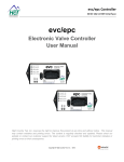
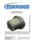
P1/PD IDEC Pump User Guide
Pump Setup and Powering IDEC Electronics
1. Plug in the CON 1 – 30 pin circular mating connector, that was supplied by
Parker, into the pump, see Figure 1.
2. Power the pump electronics through CON 1 according to the pin connections as
stated in Table 1.
a. Pins 1 and 2, the EXT PWR, +24VDC (nominal) regulated power supply
at 3.0 Amps minimum. Connect +24VDC to both.
b. Pins 3 and 4, must be connected to external power ground, 0 volts.
c. All of the connecting wires must be 16 AWG minimum.
d. Pin 11, PUMP ENABLE INPUT, must have +24VDC (nominal) to
operate the pump, remove the +24VDC (nominal) from pin 11 and the
pump will go to 0% displacement and minimum pressure setting.
3. With Pins 1, 2, and 11 having +24VDC (nominal) and pins 3 and 4 connected to
external power ground, the pump is now ready to operate.
4. The displacement and pressure commands can be sent in two ways. They can be
a fixed value which can be changed by computer through the RS-232 connector,
see the section on “How to use the GUI”. A second option is a proportional
command that is changed with a voltage or current signal. See table 1 for the pin
assignment of the 30 pin connector, and Figure 3 for a wiring schematic.
5. The X-port on the housing is ported to an extra pressure transducer that is
available for use, see Figure 2. In load sense control mode this port can be used
for the hydraulic load sense line.
6. The S-port on the housing is for the servo pressure, see Figure 2 for the location
of the port. The servo pressure should be 25 to 35 Bar and the capacity 4 to 6
Lpm. Two check valves in the housing sends the higher pressure, of the servo or
the pump outlet, to the control piston of the pump.
a. If the pump outlet pressure is below 25 Bar / 363 psi and/or true zero
displacement/flow is desired the “S” servo port must be used to maintain a
pressure of 25 Bar / 363 psi or greater for pump control.
b. CAUTION: If the servo port is used and the control valve current goes to
zero when using the spring offset to zero flow valve, the pump will go to
mechanical over center stops. Resulting in -100 percent over center
condition for XS specified pumps and -10% for PS specified pumps,
which would pump oil from the outlet to the inlet back to the reservoir
possibly cavitating the pump.
Figure 1: A View of the pump showing the connection locations of the 30 pin
connector, and 3 pin RS-232 connector.
“X” PRESSURE
PORT
“S” PORT
EXTERNAL
SERVO
Figure 2: Drawing of P1/PD 75cc IDEC pump with electronic control
showing location of “X” pressure port and “S” External Servo Port.
TABLE 1: CON 1 – 30 Pin Circular Connector Pin Assignment
PIN
Designation
Signal
Input/Output
1
EXT PWR (+24V)
(+20 ~ 36 V)
Input
2
EXT PWR (+24V)
(+20 ~ 36 V)
Input
3
EXT PWR GND
(0 V)
Input
4
EXT PWR GND
(0 V)
Input
5
+5 VOLTS OUTPUT
(+5 V @ 10 mA)
Output
6
-5 VOLTS OUTPUT
(-5 V @ 10 mA)
Output
7
SIGNAL GND
(0 V)
Input/Output
8
TRAPPED VOLUME 1
(+12 ~ 36 V)
Input
9
TRAPPED VOLUME 2
(+12 ~ 36 V)
Input
10
TRAPPED VOLUME 3
(+12 ~ 36 V)
Input
11
PUMP ENABLE INPUT (+24V)
(+12 ~ 36 V)
Input
12
EXTERNAL SHAFT SPEED PULSE
(+12 ~ 36 V)
Input
13
EXTERNAL SHAFT SPEED ANALOG
(0 ~ ± 20 mA)
Input
14
PUMP READY OUTPUT
(+5 V @ 5 mA)
Output
(0 ~ ± 5 V)
Input
(0 ~ ± 20 mA)
Input
(0 ~ ± 5 V)
Input
(0 ~ ± 20 mA)
Input
(0 ~ ± 5 V)
Input
(0 ~ ± 20 mA)
Input
15
16
17
18
19
20
TORQUE LIMIT SUM/ANTISTALL SUM #2
(VOLT)
TORQUE LIMIT SUM/ANTISTALL SUM #2
(AMP)
TORQUE LIMIT SUM/ANTISTALL SUM #1
(VOLT)
TORQUE LIMIT SUM/ANTISTALL SUM #1
(AMP)
TORQUE LIMIT/ANTISTALL COMMAND
VOLT
TORQUE LIMIT/ANTISTALL COMMAND
AMPS
21
PRESSURE COMMAND VOLT
(0 to +5 V)
Input
22
PRESSURE COMMAND AMPS
(0 ~ 20 mA)
Input
23
PORT B PRESSURE INPUT
(0 ~ ± 20 mA)
Input
24
EXTERNAL LOAD SENSE INPUT
(0 ~ ± 20 mA)
Input
25
PUMP IN PRESSURE MODE INDICATOR
(+5 V @ 5 mA)
Output
26
PUMP OUTLET PRESSURE
(0.3 ~ 3.0 V)
Output
27
DISPLACEMENT/LOAD SENSE CMD VOLT
(0 ~ ± 5 V)
Input
28
DISPLACEMENT/LOAD SENSE CMD AMPS
(0 ~ ± 20 mA)
Input
29
CAM POSITION
(0.3 ~ 3.0 V)
Output
30
ANALOG OUT
(0 ~ ± 5 V)
Output
Figure 3: Wiring schematic of 30 pin cable
Loading the GUI (Graphical User Interface) Software
7. Turn on the computer
8. Install the GUI software onto the computer.
a. Insert CD into CD drive
b. Run the file named “setup.exe”
c. Follow installation instructions
d. If the computer already has an older version of the GUI, the “setup.exe”
file will need to be run twice.
i. The first time the “setup.exe” file is run it will prompt the user to
uninstall the older version GUI.
ii. Run the “setup.exe” file again and it will prompt the user to install
the new version of the GUI.
e. To place the P1/PD IDEC Gui on the desktop a shortcut needs to be
created. Do Not try to copy the executable file to the desktop. Create a
shortcut to the executable and place the shortcut on the desktop.
9. System Requirements
a. Desktop or laptop computer with Windows 98/NT/2000/XP operating
system
How to use the GUI (Graphical User Interface)
10. Plug in CON 2 (3 pin RS-232 connector) into the pump, see Figure 1, and plug
the DB9 connector into the computer.
11. Make certain the pump electronics are powered with 24VDC according to the
“Pump Setup and Powering IDEC Electronics” section.
12. Start the P1/PD GUI program.
13. The upper left of the GUI should say STATUS Online.
a. If the status says online the computer is communicating with the pump
correctly.
b. If the computer isn’t communicating with the pump, turn the power to the
electronics off, close the GUI down, check the RS-232 connector and the
30 pin connector to make certain there is a good connection.
i. Turn the power back on to the pump electronics, wait a couple of
seconds and then start the GUI software.
ii. If there is still a problem, make certain that the serial port is
“enabled” in the BIOS setup.
14. The “Quick View” menu option will be the screen that comes up when first
starting the GUI, see Figure 4.
F
A
B
G
C
D
H
E
I
J
K
L
M
N
O
P
Figure 4: Quick View screen of P1/PD GUI
A
Pump Enabled: Green Light means pin 11 on 30 pin cable has +24VDC.
B
Controller Ready: Green Light means pin 14 of 30 pin cable is outputting 5 VDC
indicating the IDEC is functioning properly.
C
Pump Mode: Indicates what control mode the controller is currently in.
D
Access Level: (Display Only) – customer can only change the units, (User) –
customer can change pump settings, and (Advanced) – Parker only, factory
calibration and control gains can be changed.
E
Units can be changed from Metric to English.
F
User can change Displacement Cmd Type and Pressure Command Type from
digital (PC) to analog (30 pin cable).
G
The Displacement Command setting can be changed with the PC if the
Displacement Cmd Type is set to Digital.
H
The actual pump displacement in (%).
I
Pressure Limit Setting if the Pressure Command Type is set to Digital.
J
Actual Outlet Pump Pressure.
K
Pressure at the “X” port.
L
O
Load Sense Margin setting when Load Sense Press Cmd Type is Digital.
Calculated delta P: Difference between Pump pressure and the “X” port pressure.
Pump speed.
Temperature of the electronics.
P
Calculated power using the displacement, pressure, and speed transducers.
M
N
15. NOTE: Changing the Pressure Command Type to Digital will block the analog
signal of pin 21 or 22 from controlling the pressure limit setting of the pump.
Changing the Displacement Cmd Type to Digital will block the analog signal at
pin 27 or 28 from controlling the displacement setting of the pump. With the
Command Type set to Digital a constant value is used to command the respective
control mode, even if the GUI is not running.
A
B
C
D
E
F
G
H
I
Figure 5: Pump Settings screen of P1/PD GUI
A
B
C
D
E
F
G
H
I
Pump Settings Tab, click on the tabs to switch between screens.
Command Type: Digital – a fixed setting, Analog – Proportional to current or
voltage depending on user selection.
Save to Controller NOVRAM: this button needs to be clicked anytime the pump
settings have been changed and the user wants them saved to the controller. If not
when the IDEC is powered down and then powered back up the last saved
parameters will be in the controller.
Maximum Displacement, similar to a max volume stop, for example if 80% is
entered and the pump is in analog mode then 5 volts will now correspond to 80%
instead of 100% displacement.
Maximum Pressure, for example if 210 bar is entered then 5 volts would
correspond to 210 bar instead of 280 bar.
Load Sense margin setting, changing here will also change the value in the Quick
View Screen.
Analog Output Type: User selectable option for what signal to output on pin 30.
Ramp up and Ramp down: 1 sec corresponds for the time to go from 0 to 100 %.
If you want to go from 50 to 100% in 1 sec, then put 2 sec as the ramp time.
Pump Control Mode: This identifies all the control options available and running.
16. Figure 6, shows the “File Save/Load” screen where the different signals can be
turned on and off for display purposes and logging purposes.
A
B
C
Figure 6: File Save/Load screen of P1/PD GUI
A
Save and Save as will let the user save the pump parameter settings and values to
the computer that is connected to the IDEC through the RS-232 cable.
B
Load file to pump: will load the saved pump parameter settings and values from
the file on the computer to the IDEC pump.
C
View Settings: Allows the user to see all the pump parameters and their settings
or values.
17. The GUI has data logging capability. Figure 8, shows the “Data log” screen
where the different signals can be logged to a .csv file which is excel compatible.
Make certain the signals to be logged are checked in the “Pump Data” screen,
Figure 7. If the signal is not checked it will not be logged.
i.
A
B
Figure 7: Pump Data screen of P1/PD GUI
A
B
On/Off All will show all the signals on the graph and save all the signals when
using the Data Log screen when checked. Unchecking On/Off All clears all the
signals from the screen and none of the signals will be saved when using the Data
Log screen.
Each of the signals can individually be checked on or off depending on what
signals the user wants displayed and what signals the user wants saved when
using the Data Log screen.
18. Figure 8 shows the data logging screen. The following steps will describe how to
log and save data.
a. Click the “Set Folder” button to select the desired location to save the log
file on your computer.
b. Click the “Set Log File” button to name the log file.
i. This needs to be done before starting to log data.
c. Select the time interval for the data to be logged.
i. The “log every data point”, will log data as fast as the speed of
data transfer of your computer and RS-232 connection.
ii. The endurance log will log data at the specified interval as fast as
the RS-232 connection allows for as long as the user specifies.
iii. Data can also be logged at specified intervals, 1 sec., 10 sec., etc.
d. Click on the Start Button to start and stop the data logging.
B
A
C
D
E
F
G
H
I
Figure 8: Data log screen of P1/PD GUI
A
Start Data Log button; make certain to specify log interval and set up a log file
name before starting to log data. Once START is clicked it changes to the STOP
button.
B
Clicking the save and close data button will close the log file otherwise clicking
the start and stop button will keep adding data to the same log file.
C
Log interval: Specify how often data is to be logged, 1 sec, 10 sec, etc. Also log
every data point can be selected, but then this is not a fixed time interval. If
endurance logging is selected then the user needs to specify how often to activate
and for how long.
D
Activate every, is only used when endurance logging is selected.
E
For endurance logging the data is logged every data point for as long as specified.
For example if your computer is capable of 10 data points per second then if the
user specifies to long for 2 seconds then 20 data points will be logged.
F
The user can specify how often the data is saved to the .csv file in case the
computer loses power the data will not be lost.
G
The user must specify a filename before starting to log data.
H
The user can specify where on the computer the log data file should be saved.
I
The file is a .csv file which is excel compatible, so there is a limited amount of
data that can be saved.
A
D
B
E
F
C
Figure 9: Tools screen of P1/PD GUI
A
Controller Tuning Mode: This is Advanced level access for Manufacture to
change the control gain settings of the pump.
B
Diagnostic Mode: This communicates the raw data for troubleshooting ability.
C
Factory Calibration: All the sensors are calibrated at the factory.
D
Save controller settings to non-volatile memory or NOVRAM. If the user
changes any of the pump settings or command types this button needs to be
clicked either here or on the pump settings screen. Otherwise when the IDEC is
powered down and then back on the lasted saved settings will be what the IDEC
uses.
E
Comport Details: lets the user know things about the RS-232 connection. For
example how many data points a second are being transferred.
F
Update pump controller software: The user clicks this button and browses to the
location of the .hex file that the manufacture sent to the user for the latest pump
controller software version. Go to “Downloading New Pump Controller
Software” section for a step by step how to guide.
Downloading New Pump Controller Software
19. NOTE: Steps 20 through 29 are only done when the user receives an update new
controller software file from the manufacturer.
20. Make certain that the pump is NOT running
21. Connect the 3 pin RS-232 connector to the pump according to Figure 1, and
connect the other end of the cable with the db9 connector to a computer.
22. Turn on the 24VDC power to the pump electronics.
23. Run the GUI (Graphical User Interface) software. If the computer does not
contain the GUI software, go to the section “Loading the GUI software” in this
user manual to find out how to install the GUI software.
24. With the GUI running go to the tools menu item, see Figure 9.
25. Click on the “Update Pump Controller Software” button.
26. Find the new .hex file received from the manufacturer to be downloaded using the
file open dialog box.
27. Once you click on the new pump controller software .hex file, then click on the
“download” button.
28. Once the download is completed the GUI will ask you to turn off the power to the
pump electronics wait a couple of seconds and then turn the power back on.
29. After turning the power to the pump electronics back on wait a couple of seconds
and then click “Yes” to reconnect the GUI with the pump.