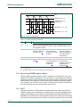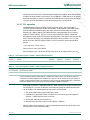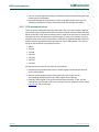
1
D
D
D
D
D
R
R
R
R
R
D
R
R
R
A
FT
R
A
F
FT
FT
A
A
R
R
D
D
D
D
SPEN
MSTR
SPR0
SPR1
CPOL
CPHA
MSTR
DORD
SPEN
SS
P2.4
SPI
interrupt
request
internal
data
bus
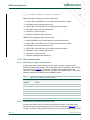
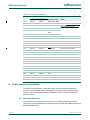
002aaa900
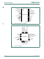
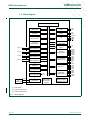
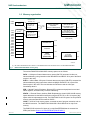
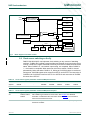
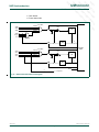
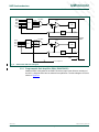
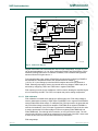
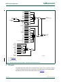
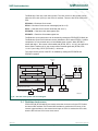
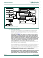
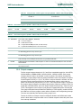
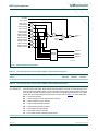
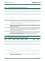
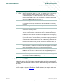
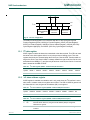
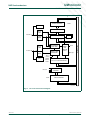
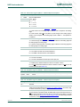
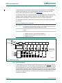
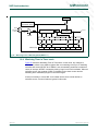
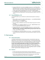
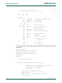
Fig 42. SPI block diagram
The SPI interface has four pins: SPICLK, MOSI, MISO and SS:
• SPICLK, MOSI and MISO are typically tied together between two or more SPI
devices. Data flows from master to slave on the MOSI (Master Out Slave In) pin and
flows from slave to master on the MISO (Master In Slave Out) pin. The SPICLK signal
is output in the master mode and is input in the slave mode. If the SPI system is
disabled, i.e. SPEN (SPCTL.6) = 0 (reset value), these pins are configured for port
functions.
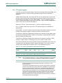
• SS is the optional slave select pin. In a typical configuration, an SPI master asserts
one of its port pins to select one SPI device as the current slave. An SPI slave device
uses its SS pin to determine whether it is selected. The SS is ignored if any of the
following conditions are true:
– If the SPI system is disabled, i.e. SPEN (SPCTL.6) = 0 (reset value)
– If the SPI is configured as a master, i.e., MSTR (SPCTL.4) = 1, and P2.4 is
configured as an output (via the P2M1.4 and P2M2.4 SFR bits);
– If the SS pin is ignored, i.e. SSIG (SPCTL.7) bit = 1, this pin is configured for port
functions.
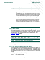
Note that even if the SPI is configured as a master (MSTR = 1), it can still be converted to
a slave by driving the SS pin low (if P2.4 is configured as input and SSIG = 0). Should this
happen, the SPIF bit (SPSTAT.7) will be set (see Section 13.4 “Mode change on SS”)
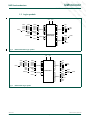
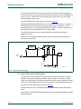
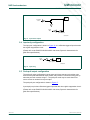
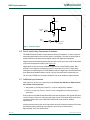
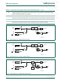
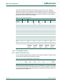
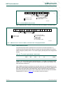
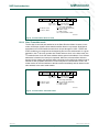
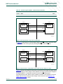
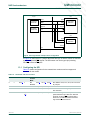
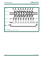
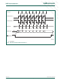
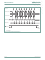
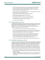
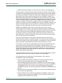
Typical connections are shown in Figure 43 to Figure 45.
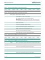
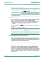
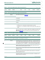
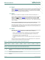
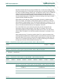
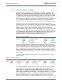
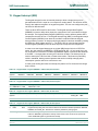
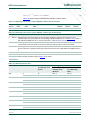
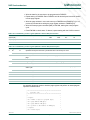
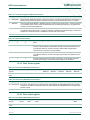
Table 106. SPI Control register (SPCTL - address E2h) bit allocation
Bit
7
6
5
4
3
2
1
0
Symbol
SSIG
SPEN
DORD
MSTR
CPOL
CPHA
SPR1
SPR0
Reset
0
0
0
0
0
1
0
0
<Document ID>
© NXP B.V. 2009. All rights reserved.
Rev. 01.xx — 5 February 2009
109 of 172
A
SSIG
R
SPR0
D
WCOL
D
SPICLK
P2.5
SPI CONTROL REGISTER
SPI STATUS REGISTER
FT
MSTR
SPEN
A
S
M
CLOCK LOGIC
MOSI
P2.2
R
SPI clock (master)
SPI CONTROL
D
clock
SELECT
FT
PIN
CONTROL
LOGIC
READ DATA BUFFER
DIVIDER
BY 4, 16, 64, 128
FT
A
A
R
R
D
MISO
P2.3
M
S
8-BIT SHIFT REGISTER
SPR1
D
R
FT
FT
A
A
R
R
D
D
D
CPU clock
SPIF
FT
FT
FT
FT
A
A
A
A
R
R
D
D
D
S
M
FT
FT
FT
FT
FT
UM<nnnnn>
P89LPC9331/9341/9351 User manual
User manual
A
A
A
A
A
NXP Semiconductors