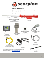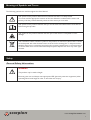
1
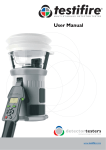
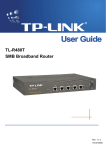
scorpion
®
Remote Tester for Point Smoke Detectors
& Aspirating Smoke Detection (ASD) Systems
User Manual
*Note: The ASD pipe and brackets shown in the illustration above and
within this manual are not part of the Scorpion ASD product line.
www.scorpion-tester.com
scorpion
®
User Manual
This manual provides information for the correct use of scorpion®
Remote Detector Test System
System Components:
Scorpion ASD Head Unit Kit
SCORP 2001
Scorpion Point Head Unit Kit
SCORP 1001
(including Door Detectors)
Scorpion Access Point
SCORP 25
(for single heads)
Scorpion Power Pack
SCORP 50
Scorpion Wall Mounted
Scorpion Portable
Controller
Controller
SCORP 8000
SCORP
7000
(for single heads) (for multiple heads)
Includes Control Cable (SCORP 1054)
and Battery Cable (SCORP 60)
Scorpion Control Cable
SPARE 1054
(for connecting Portable
Controller, SCORP 7000 to
Access Point, SCORP 25)
Scorpion Battery Cable
SCORP 60
(for connecting Solo 760
Battery Baton to Scorpion
Control Panel)
Solo Universal Fast
Battery Charger
SOLO 726
For any additional information or technical support, please visit
the Scorpion web site at: www.scorpion-tester.com
Solo Battery Baton
(optional)
SOLO 760
www.scorpion-tester.com
i
Meanings of Symbols and Terms
The following symbols are used throughout this User Manual.
This symbol on the product and literature indicates that there is a safety hazard.
You must read the appropriate sections of the User Manual to understand the nature and
severity of all the potential hazards present and the action you must take.
This symbol on the product indicates that you should read and understand this User Manual
before using this product.
This symbol on the product indicates that this part of the device is susceptible to static
damage.
The crossed-out refuse container symbol on this product or literature indicates that it should
not be disposed with other business waste at the end of its working life. To help ensure that
valuable resources are reused and recycled, and to prevent possible harm to the environment
or human health from uncontrolled waste disposal, please separate this from any other types
of waste.
Safety
General Safety Information
WARNING
This product may be used at height.
Exercise great care and always wear appropriate PPE (personal protective equipment) when
operating above head height in order to avoid the risk of injury.
scorpion
®
www.scorpion-tester.com
ii
Important Information
l
Read this User Manual completely before using your Scorpion System.
l
Save this User Manual - Save all safety and operational instructions for future reference.
l
Take note of the Cautions and Warnings - Read carefully and follow all warning labels on the product and those
described in this User Manual.
l
Installation of the Scorpion system must not obstruct or impair the operation of the fire system.
CAUTION
Environment - This product is designed for indoor use only and should not be subject to, or
used in, a wet, high humidity or dusty environment. Installation in these environments may reduce
the life and/or performance of the system. Scorpion is not designed for use in hazardous areas
(those containing explosive vapour or dust). Do not install where insects are likely to interfere
with the detector as it is also possible they will interfere with Scorpion in the same way.
l
Location - Whenever possible, the Scorpion Head Unit should be positioned where there is no movement of air.
In situations where there is a draft, position the head unit smoke nozzle 'upwind' of the direction of air
flow. In turbulent air the smoke generated may not reach the Point detector or ASD pipe inlet.
l
Servicing
Direction of ambient air flow
l
Direction of ambient air flow
There are no user serviceable parts in the Scorpion Head Unit.
l Any
attempt to open or tamper with the Head Unit or Controller, other than shown in this manual will invalidate any
warranty or claim against No Climb Products Ltd.
l The
l
Scorpion Controllers contain a safety fuse which can be replaced if necessary.
General Advice
l Always
allow the equipment to reach ambient temperature before use (e.g. after removing from packaging) to
prevent condensation damage.
CAUTION
Stop using Scorpion immediately if you notice any unusual odours; liquids or noise coming from it.
Switch off immediately and consult technical support.
Do not paint the Head Unit
l If
your Scorpion unit becomes damaged do not use it. Switch off immediately and consult technical support.
l Scorpion
is not designed for use in hazardous areas (those containing explosive vapour or dust).
scorpion
®
www.scorpion-tester.com
iii
WARNING
Scorpion is not designed for use in hazardous areas (those containing explosive vapour or dust).
l Use
only approved accessories that are recommended by the manufacturer.
l The
Scorpion Battery Pack or Solo Battery Baton should be removed when Scorpion is not in use. This will
prevent gradual discharge of the battery and prevent possible accidental or malicious operation of the head unit.
l Always
use a fully charged battery when commissioning the system.
CAUTION
Do not use your Scorpion if it is not operating properly. Consult the Troubleshooting section of
this manual, and if required, seek technical advice
scorpion
®
www.scorpion-tester.com
iv
Table of Contents
Page No.
5
5
5
5
1.
General Instructions
1.1
Warranty
1.2
Acknowledgement
1.3
Recycling
2.
Introduction
6
3.
Applications
3.1
Installation Examples
7
7
4.
Parts Identification
8
5.
Scorpion Components
5.1
Point Head Unit
5.2
ASD Head Unit
5.3
Portable Controller Interface
5.4
Wall Mounted Controller Interface
9
9
9
10
11
6.
Installation
6.1
Scorpion Head Units
6.2
Head Unit Wiring
6.3
Cabling
6.4
Point Head Unit Installation
6.5
Do's and Don'ts for Point Head Unit Installation
6.6
ASD Head Unit Installation
6.7
Do's and Don'ts for ASD Head Unit Installation
6.8
Access Point Installation
6.9
Wall Mounted Control Panel Installation
12
12
12
13
13
15
16
17
17
18
7.
Using Scorpion
7.1
Charging the Scorpion Battery Pack (or Solo Battery Baton)
7.2
Connecting the Battery
7.3
Setting Test and Clear Times on the Portable Controller
7.4
Setting Test and Clear Times on the Wall Mounted Control Panel
7.5.1
Enabling the Transport Timer
7.5.2
Test Settings using the Portable Controller
7.5.3
Test Settings using the Wall Mounted Control Panel
7.6
Warnings and Error Messages
19
19
20
20
21
21
22
22
23
8.
Troubleshooting
24
9.
Service and Maintenance
9.1
Scorpion Head Units
9.2
Scorpion Portable Controller and Wall Mounted Control Panel
9.3
Batteries and Battery Charger
25
25
25
scorpion
®
www.scorpion-tester.com
iv
1. General Instructions
1.1 Warranty
In addition to any other express warranty given in writing by the Company in relation to the Goods, the Company
warrants that the Goods supplied under the terms and conditions will be in accordance with the specification
(if any) contained in the Purchase Order, and will be free from defects in workmanship and material for a period of
18 months from the date of delivery to the Buyer or for a period of 12 months after the date of sale by the Buyer
to the final customer whichever period is the shorter. Warranty is limited to the replacement of Scorpion system
only.
Keep a record of the serial numbers of the components, particularly the Head Units, as these will be needed to
verify the warranty status. Make a note of these before installation as they will be inaccessibly once the Head Unit
is fitted to the mounting bracket. The serial number is printed on the Head Unit label and on the packaging label.
Make a note of the model, serial number, and date of purchase.
1.2 Acknowledgement
Scorpion®is a registered mark of No Climb Products Ltd. All other brand names mentioned are trademarks
or registered marks of their respective holders, and are hereby acknowledged. ©2012 No Climb Products Ltd. All
Rights Reserved.
1.3 Recycling
The packaging can be easily separated into
the following materials:
l
Cardboard (outer box)
Cardboard (inner buffers, boxes)
l Polyethylene (bags)
l Plastic / metal (any items or accessories
that are not required for a specific
installation)
l
Please dispose in line with local
environmental requirements.
CE Declaration
This product and its associated components are designed and manufactured to be fully compliant with the
requirements of the following EU Directives for CE marking:
l
l
l
EMC Directive 2004/108/EC of the European Parliament and of the Council of 15 December 2004 on the
approximation of the laws of the Member States relating to electromagnetic compatibility.
Low Voltage Directive 2006/95/EC of the European Parliament and of the Council of 12 December 2006 on the
harmonisation of the laws of Member States relating to electrical equipment designed for use within certain
voltage limits.
RoHS Directive 2011/65/EU of the European Parliament and of the Council of 8 June 2011 on the restriction of
the use of certain hazardous substances in electrical and electronic equipment.
WEEE (Waste Electrical & Electronic Equipment) Regulations 2006
Scorpion components are suitably marked to be recycled in accordance with your local environmental
requirements. When supplied as B2B EEE, the provider invokes regulation 9.2 and passes all WEE obligations to
the end user.
scorpion
®
www.scorpion-tester.com
page 5
2. Introduction
Thank you for purchasing the Scorpion Remote Test System.
Scorpion is a unique, functional remote smoke detector test system that assists compliance with codes
and standards for testing fire detection systems, while delivering radical time, cost and disruption savings
and considerable enhancements to safety.
Scorpion can be used on Aspirating Systems (ASD) as well as Point smoke detectors, on new or retrofit
installations. Point and ASD heads can be connected to the same Control Panel and can be located up to
100m away from the panel, depending on the cable type used.
Each Head Unit will provide in excess of 240 tests of 15 seconds each.
Scorpion for Point Smoke Detectors
The Scorpion Point Head is a smoke generator which is permanently installed adjacent to a standard
point smoke detector but which uses its own cabling and remains discrete from the fire detection system.
A Clearing function is available that blows air through the detector which helps remove smoke from the
detector to enable it to reset more quickly, and reduces repeat alarms.
Scorpion for ASD systems
Traditional post commissioning ASD testing is generally performed by trying to introduce a test smoke
(often of inappropriate suitability or even questionable quality) into individual sampling points. Not only
can this be highly impractical but it can also contaminate an ASD system. Scorpion offers an approved,
benign and effectively non contaminating test particulate delivered in a controlled and repeatable manner.
With a Scorpion ASD Head Unit permanently positioned at the end of a pipe run, a repeatable and
consistent test is achieved throughout the system's lifetime. By recording the moment of Scorpion
activation and the moment of alarm signal, the transport time is measured. Comparing this against the
retained commissioning data, previous tests and the acceptable tolerances enables judgments to be made
regarding the integrity of the aspirating system.
If you require additional information or assistance in the use of Scorpion, please visit the support area of
our web site, or contact our technical support department as detailed on the Support page of this User
Manual.
scorpion
®
www.scorpion-tester.com
page 6
3. Applications
3.1 Installation Examples
Installation Example (Point)
l
Scorpion is designed for use on optical
(photoelectric) and ionization smoke
detectors.
l
Certain combination point detectors
(combinations of smoke, heat, or CO)
cannot be activated by the introduction of
a single stimulus. In these cases, Scorpion
will not work and a Multi-Stimulus
Detector Tester should be used
(see: www.testifire.com).
l
The head unit can be up to 100m away
(cable length) from the Access Point /
Wall Mounted Controller depending on
the cable type used.
l
l
Scorpion Head Unit
Point Smoke Detector
Scorpion Head Unit
Point Smoke Detector
Scorpion
Circuit
(100m max.)*
One Access Point is required for each
head unit or the Wall Mounted Controller
can be used for up to 8 head units.
Scorpion is activated by connecting the
portable battery (either the Scorpion
Battery Pack or a SOLO 760 Battery
Baton) to the relevant Scorpion Controller.
Scorpion
Wall Mounted
Control Panel
(for multiple heads)
Scorpion
Portable
Controller
(for single heads)
Scorpion Access
Point
(1 per Head Unit)
Scorpion
Battery Pack
Installation Example (ASD)
The Portable Controller is connected to
an Access Point (and Scorpion Head Unit
adjacent to the relevant detector) and is
used to run a test.
Air Sampling
Points
Aspirating
Sampling
Pipe
Scorpion ASD
Head Unit
End Hole
Presenter
The Wall Mounted Control Panel only
needs a battery connected to provide the
power to run a test.
NOTE: The default smoke generation
time is set to 15 seconds. The majority of
point and ASD system detectors should
activate within this time period. If the
detector does not activate refer to section
7.3 of this manual to adjust the timer.
If the detector does not activate after a
long period or repeated tests it may be
faulty and need replacing.
Always use the shortest time required to
activate the detector.
Scorpion
Circuit
(100m max.)*
Remote
Air Sampling
Points
Suspended
Ceiling
ASD System
Detector
Scorpion
Wall Mounted
Control Panel
(for multiple heads)
Scorpion Access
Point
(1 per Head Unit)
Scorpion
Portable
Controller
(for single heads)
Scorpion
Battery Pack
*Depending no cable type (see Section 6.3)
scorpion
®
www.scorpion-tester.com
page 7
4. Parts Identification
Scorpion ASD Head Unit Kit
SCORP 2001
Scorpion Point Head Unit Kit
SCORP 1001
(including Door Detectors)
Scorpion Access Point
SCORP 25
(for single heads)
Scorpion Power Pack
SCORP 50
Scorpion Wall Mounted
Control Panel
Scorpion Portable
SCORP 8000
Controller
(for multiple heads)
SCORP 7000 (for single heads) Includes Control Cable (SCORP 1054)
and Battery Cable (SCORP 60)
Scorpion Control Cable
SPARE 1054
(for connecting Portable
Controller, SCORP 7000 to
Access Point, SCORP 25)
Scorpion Battery Cable
SCORP 60
(for connecting Solo 760
Battery Baton to Scorpion
Control Panel)
Solo Universal Fast
Battery Charger
SOLO 726
Solo Battery Baton
(optional)
SOLO 760
For any additional information or technical support, please visit
the Scorpion web site at: www.scorpion-tester.com
scorpion
®
www.scorpion-tester.com
page 8
5. Scorpion Components
5.1 Point Head Unit
Terminal
Cover
Point Head Unit
Smoke Presenter
& Bracket Screws
(25/35/70 mm length)
Outer Part of
Transport Pin
Transport Pin
Cable Removal
Tool
Point Bracket (A)
Inner Part of
Transport Pin
Fuel Breather Plug
Point Bracket (B)
Locking
Ring
Point Smoke
Presenter
Flexible Tube (Point)
5.2 ASD Head Unit
ASD Head Unit
Outer Part of
Transport Pin
Terminal
Cover
Cable Removal
Tool
Inner Part of
Transport Pin
Transport
Pin
Fuel Breather Plug
ASD Bracket
ASD Pipe Clips
ASD End
Cap Smoke
Presenter
Flexible Tube (ASD)
scorpion
®
ASD Sampling
Hole Smoke
Presenter
Self-adhesive
pads for securing
Smoke Presenters
www.scorpion-tester.com
page 9
5.3 Portable Controller Interface
Battery Status Indicator
Smoke Test Status
POWER Button
START Test
STOP / EXIT
Transport Timer Status
Clearing Status
Adjust Smoke or Clearing time UP / DOWN
Set Smoke Time
Set Clearing Time
Display
Indicates:
- Firmware version on power-up
- Countdown timer (5 sec.) during warm-up when in Point Detector mode
- Countdown timer (5 sec.) during warm-up followed by Transport Time when in ASD mode (i.e. Transport Timer is active)
- “C” implies incorrect or no cable connection
Display
- Three flashing dots indicate the internal fuse has blown (see Section 8)
Power Button
- Press and hold to switch the Controller ON and OFF
- The Controller will automatically switch OFF after 10 minutes without use
RUN TEST Button
- Used to start a test (smoke generation followed by clearing)
STOP / EXIT Button
- Used to stop test (stop smoke generation and start clearing, or to stop clearing, or to stop
the timer)
- When in Smoke Time or Clear Time function, this exit button takes the user out of the
function without saving changes
- Press for 3 seconds to activate or deactivate the transport timer
SMOKE
CLEAR
SMOKE TIME
- Used to change the smoke duration saved in the controller
- Press once to enter the change smoke time function, and again to save the time and exit
CLEAR TIME
- Used to change the clearing duration saved in the controller
- Press once to enter the change clear time function, and again to save the time and exit
UP / DOWN Button
- When the SET SMOKE or SET CLEAR button is pressed:
- the UP button increases the time
- the DOWN button decreases the time
Battery Status Indicator
- Glows red up when battery power is low. Glows Green when battery level is ok
TIMER Indicator
- Lights up when timer is active
- The display then indicates the time since smoke generation started
SMOKE
SMOKE Indicator
- Test cycle in progress (smoke being generated)
CLEAR
CLEAR Indicator
- Clearing (detector purging) in progress
scorpion
®
www.scorpion-tester.com
page 10
5.4 Wall Mounted Control Panel Interface
Battery Status Indicator
Display
000
Time Indicator
UP Button
DOWN Button
RUN Button
STOP Button
TEST
Smoke Test Indicator
Smoke Time Button
(recessed)
CLEAR
Clearing Indicator
Clearing Time Button
(recessed)
scorpion
®
REMOTE DETECTOR
TEST TECHNOLOGY
Display
Indicates:
- Head Unit number (1 - 8)
- Timer (counting up in seconds when the ‘time indicator’ LED is on)
Display
Three flashing points indicate a fault has caused the fuse to blow (see Section 9)
UP Button
- Used to select Scorpion Head Unit or adjust timer
- When TEST or CLEAR recessed button is pressed, the UP button increases the time
DOWN Button
- Used to select Scorpion Head Unit or adjust timer
- When TEST or CLEAR recessed button is pressed, the DOWN button decreases the time
RUN Button
- Used to start test (smoke generation and/or clearing)
STOP Button
- Used to stop test (smoke generation and start clearing, or to stop clearing, or to stop timer)
- Press for 3 seconds to activate or deactivate timer
Timer Indicator
- Lights up when timer is active
- The display then indicates the time since smoke generation and/or clearing cycle started
TEST
CLEAR
TEST Indicator
- Test cycle in progress (smoke generated and /or clearing functions)
- Recessed Button: Press and hold with small pointed tool to change smoke duration
CLEAR Indicator
- Clearing (detector purging) in progress.
- Recessed Button: Press and hold with small pointed tool to change clearing time
Battery Status Indicator
- Glows red up when battery power is low. Glows Green when battery level is ok
scorpion
®
www.scorpion-tester.com
page 11
6. Installation
6.1 Scorpion Head Units
CAUTION
The Head Unit contains a liquid fuel, and is suitably sealed during transportation. Care must
be taken during installation to prevent the fuel from leaking (the fuel is not harmful) - see the
Safety Data Sheet (SDS) on www.scorpion-tester.com for more information.
Ensure that the Head unit is kept level (+/- 15° from horizontal) and the correct
way up at all times (labels facing upwards). Failure to do this could result in the fuel
leaking out. Only remove the Fuel Breather Plug and Transport Pin (two parts) at the
correct point during installation.
Note: Scorpion Head Units and Mounting Brackets are differentiated by their colour; white for Point Detectors and
Red for ASD Systems (one part). Both Head Units have a similar specification but their mounting brackets are
different. Please ensure you have the correct Head Unit and fittings for the application.
Fig. 1
Transport Pin
NOTE: Do not remove this pin
until just before the Head Unit is
installed. The pin consists of an
outer and inner part and they
should be removed as instructed.
IMPORTANT
Fuel Breather Plug
NOTE: Do not remove until
just before the Head Unit
is installed
There are alternative ways of installing the Scorpion
Head Units depending on the individual site
situation.
Resistance Lug
(keeps the Head Unit firmly
clamped to the bracket)
NOTE: It is very important that whichever way
you adopt to install Scorpion, the head unit must be
maintained horizontal and with the label facing
upwards once the transport pins and fuel breather
plug have been removed. This will prevent any
accidental leakage of the liquid fuel.
6.2 Head Unit Wiring
The wiring procedure is the same for both Scorpion
Point and Scorpion ASD Head Units (Point Head
Unit illustrated).
Fig. 2
Insert wires here
Fig. 3
D C B A
DO NOT USE
Terminal Cover
ABCD
1. Remove the terminal cover by squeezing and
gently pulling (Fig. 2). Loosen the cable clip
and rotate 90° (Fig. 3).
2. To connect the cable, strip the sleeve back by
approximately 10mm then push the conductor
into the same lettered terminal as used on the
Control Panel (see Section 6.9), or follow the
numbers for the Access Point (6.8).
Cable Clip
3. Rotate the cable clip back over the cable and
under the retaining pin. Re-tighten the screw.
A suitable cable tie can also be used to secure the cable to the Head Unit.
Cable Entry
Cut-out
Cable Clip
Retaining
Pin
10mm
10mm
Fig. 4
3
4. If necessary, enlarge the cable entry cut-out to suit the cable diameter and re-fit the terminal cover.
5. To remove the cable, latch the two prongs of the cable removal tool under the connector.
Push the tool upwards and pull the cable out (Fig. 14).
scorpion
®
1
2
www.scorpion-tester.com
page 12
6.3 Cabling
1. Scorpion can be connected using the following cables to give up to 100m distance between the Control Panel
and each Head Unit:
a. Fire resistant cables such as FP200 1.5mm2, Lapp J-Y(ST)Y 0.5mm2, or equivalent recommended
2
b. Maximum conductor size is 1.5mm ,
2
minimum is 0.5mm
Smoke Time
Maximum
Cable Length
1.5
15 seconds
100m
1.0
15 seconds
100m
0.5
30 seconds
75m
2
Cable Cross Section (mm )
c. 4-core cable required
d. Screened cable is not required.
Note: Smoke time is a guide only. Always use the shortest smoke time needed
to activate the fire system
2. The connector used in the Head Unit is intended for solid-core conductors for ease of installation in difficult
areas. Stranded cable may be used but would need to be tinned (soldered) or terminated with a suitable
terminal (ferrule) with an external diameter no greater than 1.5mm.
3. Each Head Unit requires three (3) conductors (A, B & C). 4-core cable is recommended with the fourth
core cut and not connected both ends.
4. Cabling must be installed in accordance with local wiring regulations. Scorpion uses battery power (nominal
7.2V, 2.2Ah).
WARNING
This product may be used at height.
Exercise great care and always wear appropriate PPE (personal protective equipment) when
operating above head height in order to avoid the risk of injury.
6.4 Point Head Unit Installation
l
The Scorpion Point Head Unit is located beside a point detector with the 'forked' end of the mounting bracket
inserted above the detector (or its base) and flush with the ceiling. For installation on sloping ceilings, the
mounting bracket will need to be bent to keep the Scorpion Head Unit horizontal to prevent the leakage of fuel
(see Section 6.3).
l
Where the air is relatively still (e.g. away from air conditioning, doors, etc) then the Head Unit can be positioned
on any convenient side of the detector.
l
In drafty locations, the head unit must be positioned 'upwind' of the detector so any air flow will blow the
Scorpion smoke towards the detector (see Section 6.3). If there is too much air flowing across the Scorpion
nozzle, then it is possible that the smoke will not reach the detector and the detector may not activate.
l
The smoke presenter can be adjusted by sliding the bracket horizontally towards or away from the detector to
which it is fixed, and vertically by unplugging the flexible tube from the nozzle and rotating the nozzle until it aligns
with the detector opening (see Fig 5).
NOTE: The flexible tube must be re-fitted after adjustment.
scorpion
®
www.scorpion-tester.com
page 13
1. Loosen the detector mounting screws
enough to allow the forked end of the
bracket to be inserted between the
detector base and the ceiling (Fig 5 A).
2. Join the two sections of the point
mounting bracket by inserting the lug
into the slot (Fig. 5 B).
Fig. 5
A
B
Fig. 6
3. Using the smoke presenter as a guide,
select the screw (25mm 35mm, or
70mm) that allows the presenter to
line up with the detector chamber
opening (Fig. 6 & 8).
(25mm)
(35mm)
(70mm)
Fig. 7
4. Secure the two sections of the bracket
with the screw and nut, then attach the
smoke presenter and its locking nut
(Fig. 6).
5. Adjust the smoke presenter nozzle so
that it aligns with the detector air
openings (Fig. 5 C & D) and is approx.
5-10 mm from the detector (E).
Re-tighten the detector screws, ensuring
the complete assembly is secure.
Fig. 8
C
D
E
NOTE: It is advisable to connect the cables
to the Head Unit before proceeding
(see Section 6.6).
6. Unscrew and remove the Fuel Breather
Plug from the head unit.
IMPORTANT: the head unit should
now be kept horizontal with the label
side facing upwards to prevent any
fuel leakage (Fig. 9).
5-10mm
Fig. 9
Fig. 10
7. Slide the head unit onto the bracket
as far as it will go (Fig. 10).
8. Remove the Transport Pin (Fig. 11).
Note: there are two parts to this pin.
Turn part F firmly in a clockwise
direction while pulling outwards.
After removing part G, turn part H
anti-clockwise and pull out.
Note: Part F is designed to be tight
and requires some effort to remove.
9. Finally, attach the flexible tube by
pushing it firmly into the head unit
and the smoke presenter (Fig. 12).
It may be necessary to trim the tube
to ensure a tight fit.
Fig. 11
F
G
G
H
H
Fig. 12
14mm
14mm
scorpion
®
www.scorpion-tester.com
page 14
6.5 Do's and Don'ts for Point Head Unit Installation
Please read: 'Important Information' (page iii) as well as these guidelines before installation.
4
Smoke is blown
through the
detector chamber
6
Smoke is blown
away from the
detector chamber
Direction of ambient air flow.
4
Direction of ambient air flow
(crosswind - e.g. from air conditioning,
open windows or doors etc.).
6
With a sloping ceiling, the bracket should
be bent and the pipe shortened so that
the Head Unit remains horizontal.
4
6
Distance is too small smoke is blown around
the detector
Distance is
correct - smoke is
blown centrally
through the detector
chamber
5-10mm (approx.)
6
Distance is too large smoke is blown under
the detector
NOTE: The above applies to all makes and sizes of
Point detector. Adjustments should be made to ensure
smoke enters the detector chamber correctly.
scorpion
®
www.scorpion-tester.com
page 15
6.6 Scorpion ASD Head Unit Installation
Please read: 'Important Information' (page ii) as well as these guidelines before installation.
l
l
l
The Scorpion Head Unit is usually fitted to the
end of a standard ASD pipe (not supplied) using
the clips and smoke presenter provided
(Fig. 13 A).
The Scorpion Head Unit can also be located
adjacent to an air sampling hole along the length
of an ASD pipe using the sampling hole
presenter (B).
C
Fig. 13
C
Fig. 14
A
B
Ensure that the Scorpion smoke presenter is a
tight fit on the pipe or pipe end cap and the
presenter does not obstruct the air sampling hole.
12mm
1. Attach either the end cap presenter (Fig. 13 A)
or the sampling hole presenter (B) to the ASD
pipe as applicable. Use the double sided selfadhesive pads provided © or a suitable glue,
to secure the presenter to the end cap or pipe.
Fig. 15
Fig. 16
2. Attach the flexible tube by pushing it firmly
into the smoke presenter (Fig. 14).
NOTE: It is advisable to connect the cables to the
Head Unit before proceeding (see Section 6.6).
Fig. 17
3. Slide the head unit on to the bracket as far as it
will go (Fig. 16).
4. Attach the head unit and bracket assembly to
the pipe but do not lock the pipe clips at this
stage to allow for adjustment (Fig. 17).
Fig. 18
D
5. Unscrew and remove the Fuel Breather Plug
from the head unit (Fig. 18).
IMPORTANT: the head unit should now
be kept horizontal with the label side facing
upwards to prevent any fuel leakage.
D
E
E
Fig. 19
6. Remove the Transport Pin (Fig. 18).
Note: there are two parts to this pin. Turn part
D firmly in a clockwise direction while pulling
outwards. After removing part D, turn part E
anti-clockwise and pull out. Note: Part D is
designed to be tight and requires some effort to
remove.
Fig. 20
“CLICK”
14mm
7. Attach the flexible tube by pushing it firmly into
the head unit and the smoke presenter (Fig. 19).
8. Finally, lock the pipe clips to secure the Scorpion
bracket to the ASD pipe by squeezing the pipe
and bracket as shown (Fig. 20).
scorpion
®
www.scorpion-tester.com
page 16
6.7 Do's and Don'ts for ASD Head Unit Installation
4
Smoke is drawn
into the ASD pipe
end cap sampling
hole
Direction of ambient air flow
6
Smoke is drawn
out of the ASD
end cap sampling
hole
Direction of ambient air flow
(crosswind - e.g. from air conditioning,
open windows or doors etc.)
4
With a vertical ASD pipe, the mounting bracket should be bent
so that the Head Unit remains horizontal. Some "improvisation"
may be required in these situations. A longer smoke pipe may be
required or the Head Unit may need to be attached to an adjacent
structure. Please contact our support department for guidance
in these circumstances.
6
NOTE: The above also applies to a sampling hole
application. Scorpion should ideally be mounted
adjacent to the furthest hole from the ASD detector.
6.8 Access Point Installation
1. Fix the pattress box provided in a suitable location.
2. Cabling for the Access Point can either be run
inside a cavity wall or can be run in conduit on the
outside of the wall.
3. Feed the cables through the break-outs in the
pattress box.
4. Connect the cables to the screw terminals
on the connector, noting the wire colours
used. The opposite end of the cable is
connected to the head unit as shown.
(Note: Applies to both ASD and Point
Head Units).
Ground (do not use)
2
ABC
D (do not use)
1
3
Scorpion Access Point
(SCORP25-001)
Cable Clip
Retaining
Pin
Scorpion Head Unit
(SCORP1001-001) or (SCORP2001-001)
Terminal 1
Terminal A
Terminal 2
Terminal B
Terminal 3
Terminal C
Note: The fourth wire (G), (D) should be cut and not connected at either end.
Note: Incorrect wiring may lead to damage to either the Controller or the Head Unit. See Section 8 for
Troubleshooting.
scorpion
®
www.scorpion-tester.com
page 17
6.9 Wall Mounted Control Panel Installation
1. The Control Panel is fixed using the two M5 slots in the rear of the box.
2. Cabling for the Control Panel can either be run inside a cavity wall with an exit hole directly behind the
Control Panel, or can be run in conduit on the outside of the wall. If using conduit, the optional spacer box
must be used to allow cable access to the sides of the panel (Fig. 21).
3. Undo the two small screws at the top of the panel and carefully remove the front face, taking care not to pull
the cable between the two parts (Fig. 22).
4. Connect the cable for each Head Unit to the appropriate screw terminals (marked CH1 to CH8) on either side
of the rear entry slot. Note which colour wires have been used for each terminal (marked A, B, C, and D).
These will connect to the corresponding terminals in the Head Unit. If using 3-core cable, connect to terminals
A, B, and C only (Fig. 23). If using 4-core cable, trim the 4th cable and do not use terminal D.
Note: Incorrect wiring may lead to damage to either the Control Panel or the Head Unit. See Section 8 for
Troubleshooting.
5. Tighten the screws on the terminals.
Fig. 21
ABC
Mounting
Slots
Fig. 22
Spare Fuse
Fig. 23
D (do not use)
D (do not use)
NEW PHOTO
scorpion
®
www.scorpion-tester.com
page 18
7. Using Scorpion
7.1 Charging the Scorpion Battery Pack or Solo Battery Baton
WARNING
Do not attempt to use or charge the battery if either the unit or the battery connection
point are damaged.
Never connect AC and DC power at the same time.
CAUTION
Store charger in a dry place (indoor use only when connected to AC mains). Danger of fire
and electric shock! Do not fast-charge a hot battery, allow the Battery Baton, or Scorpion
Battery Pack, to cool down naturally before starting a charge cycle. Allow the charger to cool
down for at least 15 minutes after one fast charge. Stop charging if the Battery Baton, or
Scorpion Battery Pack, becomes too hot during charging (>55-60°C). Do not leave
unattended whilst charging. Only clean with a dry cloth. Do not attempt to open the charger.
Repair permitted only by authorised dealer.
Battery Batons, or Scorpion Battery Pack, must be stored and charged in accordance with
stated environmental conditions.
Environment: Operating temperatures: 5°C to 45°C / 40°F to 115°F
Storage temperature: -10°C to 50°C / 15°F to 120°F
Humidity: 0-90% RH non-condensing
Only the Solo 726 charger should be used for charging Scorpion Battery Packs
or Solo Battery Batons (Fig. 24). Do not connect other types of batteries.
Danger of explosion.
l
The Scorpion Battery Pack (SCORP 50) or Solo Battery Batons (SOLO 760)
are used to power the Scorpion System, and must be charged before using Scorpion.
l
Connect the Solo 726 charger to a mains power outlet (100/240V – 50/60Hz)
or 12 volt vehicle accessory socket.
l
Connect the Scorpion Battery Pack or Solo Battery Baton to the charger via
the seven pin polarised connector and turn the locking ring (Fig. 25-26).
l
The LED will flash from red to green for around 5 minutes whilst the battery
status is checked. The LED will then turn to red to indicate fast charging,
unless the battery is fully charged, in which case it may go directly to green
(ready for use) (Fig. 27).
Scorpion Battery Pack
(SCORP 50)
Solo Battery Baton
(Solo 760)
Solo Battery Cable
(SCORP 60)
Locking Ring
Fig. 25
Fig. 26
Fig. 27
Fig. 24
scorpion
®
www.scorpion-tester.com
page 19
l
After fast charging is complete (90 minutes for a fully discharged battery), the charge is automatically converted to
a trickle charge and the LED turns to green (ready for use).
l
A red flashing LED indicates a faulty battery. Disconnect the battery from the charger and replace with a new
battery.
l
The battery charger and battery can remain connected under a trickle charge for several hours without damage
to the battery. This maintains the battery in a fully charged state, ready for use.
Note: If the battery is not to be used for some time (i.e. within the next day), it is advisable to unplug the charger
from the power supply.
l
To stop charging, disconnect the power plug before removing the battery from the charger.
l
To obtain the maximum battery life, the Scorpion Battery Pack or Solo Battery Baton should be fully discharged
before recharging when possible.
7.2 Connecting the Battery
11. Using Scorpion
l
With a Scorpion Battery Pack (SCORP 50), insert the connector at the end of the Battery Pack to the socket
at the bottom of the Scorpion Portable Controller or the Wall Mounted Controller. The connectors need to
be aligned before they can push together. Once inserted, twist the collar on the battery socket clockwise to
lock the battery into place.
l
To remove the battery, twist the collar anti-clockwise to unlock, then pull gently to disengage.
l
When using a Solo Battery Baton (SOLO 760), a Scorpion Battery Cable (SCORP 60) is required to connect
the battery baton to the Scorpion Portable Controller or Wall Mounted Controller.
7.3 Setting SMOKE and CLEAR Times on the Scorpion Portable Controller
Display
l
Connect the battery
l
Switch the Controller ON
- Press and hold the ON button
- The display shows the firmware version, then
goes blank.
Smoke Test Status
Adjust Smoke or Clearing time UP / DOWN
Stop / Exit
l
Clearing Status
Set Smoke Time
Set Clearing Time
Setting Smoke and Clear times (If required)
- The time that is required for SMOKE (the time for which smoke is generated) and CLEAR (ambient air is
blown through the detector chamber) can be changed depending on the system activation time.
SMOKE (default time is 15 seconds)
CLEAR (default time is15 seconds)
- To change the default times, press the relevant SMOKE TIME or CLEAR TIME button. The display will
show the previously set (or default time) and the Smoke or Clear status light will flash.
- Press the UP and DOWN buttons until the time required is shown. Press the SMOKE TIME or CLEAR
TIME button again to save the time and exit.
SMOKE - time range is 5 to 90 seconds CLEAR - time range is 10 to 60 seconds
- The time is now set and is saved in the Controller for future use.
- To exit without saving the times, press the Stop / Exit button.
NOTE: the CLEAR function is used to purge smoke from the detector to enable it to reset more quickly. It
cannot be used to clean the internal components of the detector. Always use the least amount of smoke required
to activate the detector.
scorpion
®
www.scorpion-tester.com
page 20
7.4 Setting TEST and CLEAR Times on the Wall Mounted Control Panel
l
The time that is required for TEST (the time for which smoke is generated) and CLEAR (ambient air is
blown through the detector chamber) can be changed depending on the system activation time.
TEST (default time is 15 seconds)
CLEAR (default time is 15 seconds)
l
Press and hold the relevant TEST or CLEAR recessed button with a small blunt tool.
l
The corresponding LED will start to flash.
l
Press the UP button to increase the time or the DOWN
button to decrease the time. The time is shown on the display.
TEST - time range is 5 to 90 seconds
CLEAR - time range is 10 to 60 seconds
l
When the required time is shown, release the TEST or CLEAR recessed button. The time is now set and is
saved in the Control Panel for future use. This time is used for all the Head Units connected to that panel.
NOTE: the CLEAR function is used to purge smoke from the detector to enable it to reset more quickly. It
cannot be used to clean the internal components of the detector.
000
UP Button
DOWN Button
START Button
STOP Button
TEST
Smoke Test Indicator
Smoke Time Button
(recessed)
CLEAR
scorpion
®
REMOTE DETECTOR
Clearing Indicator
Clearing Time Button
(recessed)
TEST TECHNOLOGY
7.5.1 Enabling the Transport Timer
l
The Transport Time is used in ASD systems, and is the time taken between the start of smoke generation and
the event appearing on the ASD panel.
l
The Timer is activated / deactivated by pressing and holding the STOP button for 3 seconds (both
Controllers).
l
The Timer Indicator LED flashes fast 3 times to show the timer has been activated, and flashes slowly for
3 times when deactivated.
l
During a test cycle, the Timer Indicator LED is illuminated and the display shows the time since the start of
smoke generation (counting up).
scorpion
®
www.scorpion-tester.com
page 21
7.5.2 Test Procedure using the Portable Controller
l
Connect the Portable Controller to a Scorpion Access Point wired to the Head Unit (Detector) under test
using the Scorpion Control Cable (SPARE 1054).
l
Switch the Controller ON.
l
“C” on the display implies that either the Control Cable is not connected properly, or that an incorrect cable
is being used.
l
Press the START button to begin the test.
l
The test will run based on the default times set for SMOKE and CLEAR unless changed (see Section 5). The
LED indicators on the front panel illuminate to show the stage of the test i.e. SMOKE or CLEAR. Once the
test has been completed, the system will stop automatically.
l
If a manual stop is needed, then press the STOP button. Depending on the stage of the test, the STOP
button will have the effect shown in the table below.
TEST STAGE
Button
START
STOP
POINT
STOP
WARM UP
SMOKING
CLEARING
DISPLAY
Head Unit warms up. Display
counts down from 5 to 0 sec.
Smoke ON, Smoke LED = ON, Display = “0"
Clearing ON, Clear LED = ON, Display = “0"
Test Ends. Display goes blank.
Head Unit warms up. Display
counts down from 5 to 0 sec.
Stops SMOKE and starts Clearing, Display = “0"
Clearing ON, Clear LED = ON, Display = “0"
Test Ends. Display goes blank.
Head Unit warms up. Display
counts down from 5 to 0 sec.
Test Ends. Display goes blank.
Stops Clearing, Display = “0"
STOP
Test Ends. Timer continues to
count up until STOP
Stops warming up
ASD
START
Head Unit warms up. Display
counts down from 5 to 0 sec.
Smoke ON, Smoke LED = ON, Transport Timer LED = ON,
Display = Time counting up
Clearing ON, Clear LED = ON, Transport Timer LED = ON,
Display = Time counting up
Test Ends. Timer continues to
count up until STOP
STOP
Head Unit warms up. Display
counts down from 5 to 0 sec.
Stops smoke, Display = Transport Timer
Clearing ON, Clear LED = ON, Transport Timer LED = ON,
Display = Transport Time
Test Ends
STOP
STOP
Head Unit warms up. Display
counts down from 5 to 0 sec.
Test Ends
Stops Clearing, Display = Transport Time
Stops warming up
Test Ends. Display goes blank.
7.5.3 Test Procedure Using The Wall Mounted Controller
l
Select the head to be tested using the UP and DOWN buttons (head number is shown on the display).
The Control Panel will allow selection of up to 8 heads, even if no head is connected to that port.
l
Press the START button to begin the test.
l
The test will run based on the times set for TEST and CLEAR (using the recessed buttons). The LED
indicators on the front panel illuminate to show the stage of the test i.e. SMOKE or CLEAR. Once the test
has been completed, the system will stop automatically.
l
If a manual stop is needed, then press the STOP button. Depending on the stage of the test, the STOP
button will have the effect shown in the table below.
TEST STAGE
Button
START
POINT/
DOOR
STOP
DETECTOR
CLEARING
Smoke ON
Clearing ON
Test Ends
Shows Head Number
Stops Smoke and starts Clearing
Clearing ON
Test Ends
Shows Head Number
Clearing OFF
Test Ends
Shows Head Number
STOP
ASD
SYSTEM
DISPLAY
SMOKING
START
Smoke ON and Timer starts
Clearing ON
Test Ends
Shows time counting up
STOP
Stops Smoke and Clock - starts Clearing
Clearing ON
Test Ends
Shows stopped time
Stops Clock
Stops Clearing
Test Ends
Shows stopped time
STOP
UP or
DOWN
Once test has stopped (either run its course
or stopped manually), any button will clear
the time from the display and allow the next
head to be selected
scorpion
®
Shows Head Number
www.scorpion-tester.com
page 22
7.6 Warnings and Errors
l
Battery Status Indicator - Glows red when battery level is low. Glows green when the level is ok.
Tests cannot made when the LED glows red and the battery will need to be recharged.
l
Error - Three flashing points on the display indicate that a fault has occurred and the Control Panel fuse has
blown (see Section 9).
l
Scorpion has a clearing function that blows air through the detector to clear the smoke more quickly. This is
part of the standard test profile (unless stopped manually). If the alarm keeps sounding, the clearing time may
not be long enough and can be increased.
l
For future tests, try reducing the smoke time to lessen the amount of smoke in the detector chamber.
scorpion
®
www.scorpion-tester.com
page 23
8. Troubleshooting
Scorpion not working
Ensure battery is fully
charged and properly
plugged in.
Ensure Portable Controller
is switched on.
Portable Controller
Wall Mounted
Controller
Is the
Controller / Panel ON
(are any lights on?)
No
Yes
Ensure battery is fully
charged, or try another
battery.
Is Battery Status
LED glowing red?
No
Yes
If display shows flashing
points, this indicates a fault
has caused the internal
fuse to blow. Check circuit
and replace fuse.
‘C’ indicates a fault with
the yellow Control Cable.
Does display
show anything ?
No
0. 0. 0.
The Controller does not
detect the presence of a
head, so will still allow a
“test” to be run on an
unused port. Ensure the
patch cable is connected
at both the Portable
Controller and Access
Point. Ensure the correct
head is selected on the
Wall Mounted Control
Panel.
ABC
Ground (do not use)
Is the correct port
selected?
No
At this stage, the Wall Mounted
Control Panel looks like it is
working correctly .
At this stage, the Portable
Controller looks like it is
working correctly.
Yes
2
D (do not use)
Control Panel CH 1
connects to Head 1,
Display = “1”, check
correctly wired .
1
3
Yes
Is smoke coming out
of the head nozzle?
Yes
Scorpion is then working.
Check the alignment of
the smoke nozzle with the
detector (smoke going
into detector ) (Section 6),
increase the smoke time
(Section 7.3) to activate
your detector, or follow
the detector’s
troubleshooting guide.
No
Is a light visible
through the mesh in
the head?
No
Check that the wiring from
the Access Point / Control Panel
to the Head Unit is correct,
conductors are properly in
the terminals, conductors
are not broken, and cable
is within CSA and length
specification.
Yes
Is the Head Unit
mounted correctly ?
No
Refer to Section 6.
Check Head Unit is
horizontal , breather plugs
(top and nose) removed,
tube connected,
no blockages?
Yes
Replace the Head Unit
.
scorpion
®
www.scorpion-tester.com
page 24
9. Service and Maintenance
9.1 Scorpion Head Units
l
There are no user serviceable parts in the Scorpion Head Unit which is permanently sealed.
l
Any attempt to open or tamper with the Scorpion Head Unit will invalidate any warranty or liability with
No Climb Products Ltd.
NOTE: The Head Unit is designed to be permanently installed providing in excess of 240 tests of 15 seconds each.
9.2 Scorpion Portable Controller and Wall Mounted Control Panel
l
The Portable Controller contains a 500mA fuse (5 x 20mm cartridge type) which can be replaced if necessary.
l
The Control Cable (yellow) can be replaced using Part No. SPARE 1054-001.
l
The Wall Mounted Control Panel contains a 500mA fuse (Littlefuse Omni-Block 500mA Farnell Part No. 9943625, or
equivalent) which can be replaced if necessary. One spare fuse supplied with each Control Panel.
l
There are no other user serviceable components in the Portable Controller or the Wall Mounted Control Panel.
9.3 Batteries and Battery Charger
l
There are no user-servicable parts in the Scorpion Battery Pack (SCORP 50-001) or the Solo Battery Baton (Solo 760-001),
or in the Solo Charger (Solo 726).
l
Any attempt to open or tamper with the batteries, charger, or any other approved Scorpion (or Solo) component will
invalidate any warranty or liability with No Climb Products Ltd.
Disposal of old product
See WEEE statement (page 5).
scorpion
®
www.scorpion-tester.com
page 25
10. Technical Specification
l
Environment
Scorpion Battery Pack
Scorpion Head Unit
Scorpion Controllers
Transport / Storage
Temperature
-20°C to +35°C
(-4°F to +95°F)
-10°C to 50°C
(14°F to 122°F)
-10°C to 50°C
(14°F to 122°F)
Storage Humidity
0-90% RH
(non-condensing)
0-90% RH
(non-condensing)
0-90% RH
(non-condensing)
Operating Temperature
+5°C to +45°C
(41°F to 113°F)
0°C to 60°C
(32°F to 140°F)
+5°C to 45°C
(41°F to 113°F)
Operating Humidity
0-85% RH
(non-condensing)
0-95% RH
(non-condensing)
0-85% RH
(non-condensing)
IP40
IP20
IP40
523g
<200g
Ingress Protection
Weights & Dimensions
139mm (W) x 81mm (L) x 48mm (H) 155mm (W) x 54mm (L) x 34mm (H)
(excluding nozzle)
<500g
100mm (W) x 225mm (L) x 40mm (H)
[Portable Controller]
155mm (W) x 150mm (L) x 37mm (H)
[Wall Mounted Controller]
Note: The Scorpion system is designed for specific applications within the above parameters. For additional information regarding
location and installation procedures, please refer to the Scorpion User Manual and Quick Start Guide at: www.scorpion-tester.com
l
Safety features
• Scorpions energized only at time of test
• Isolation between Scorpion circuit and detection system
• Internal over-current protection on Scorpion circuit
• Battery over-current cut-out
l
Power source and charge data
• Scorpion Battery Pack (SCORP 50) - NiMH rechargeable nominal 7.2v 2.2Ah
• Solo Battery Baton (Solo 760) - NiMH rechargeable nominal 7.2v 2.2Ah
• Charging time 75 - 90 minutes (when completely discharged) using Solo-726 charger
• Solo Battery Charger (Solo 726) - Input: 100-240V AC / 50/60 Hz / 0.44A
: 13.8V DC 1.8A
- Output: 8.4V DC 2A FAST
: 8.4V DC 100mA TRICKLE
Servicing intervals
• None required
• Scorpion Head Unit sealed for life (no serviceable or field replaceable parts)
• Scorpion Portable and Wall Mounted Controllers contains a fuse
l
l
Cabling
• Maximum conductor size is 1.5mm2, minimum is 0.5mm2
• Scorpion circuit wiring: FP200 1.5mm2, Lapp J-Y(ST) Y 0.5 mm , or equivalent
• Maximum cable length per Scorpion Control Panel - 100 metres(1)
• Maximum Scorpions per Access Point - 1 / per Wall Mounted Control Panel - 8
2
l
(1)
Testing Capacity
• In excess of 240 tests of 15 seconds each per Scorpion Head Unit
Depends on cable used (see Section 6.7).
scorpion
®
www.scorpion-tester.com
page 26
11. Technical Support
For support, service and further information, please contact:
No Climb Products Ltd
Edison House, 163 Dixons Hill Road, Welham Green, Herts, AL9 7JE United Kingdom
Tel: +44 (0) 1707 282760 Fax: +44 (0) 1707 282777
Email: [email protected]
Online help available at www.scorpion-tester.com/support
scorpion
®
www.scorpion-tester.com
page 27
As our policy is one of continuous improvement, details of products
described within this publication are subject to change without
notice. All information provided here is believed to be correct at the
time of going to press. Every effort has been made to ensure the
accuracy of information which is provided in good faith but nothing
contained herein is intended to incorporate any representation or
warranty, either express or implied or to form the basis of any legal
relations between the parties hereto, additional to or in lieu of such
as may be applicable to a contract of sale or purchase.
Copyright Notice: All Rights Reserved. No part of these written
materials may be reproduced or used in any form or by any means,
electronic or mechanical, including photocopying without the prior
written permission of detectortesters, No Climb Products Ltd.
No liability is assumed with the respect to the use of information
contained in these written materials or software, or for damages
resulting from use of the information contained therein.
No Climb Products Ltd
Edison House
163 Dixons Hill Road
Welham Green
Hertfordshire AL9 7JE
United Kingdom
Tel: +44 (0) 1707 282 760
Fax: +44 (0) 1707 282 777
[email protected]
www.scorpion-tester.com
LI32344-3