1
US 20130328671A1
(19) United States
(12) Patent Application Publication (10) Pub. No.: US 2013/0328671 A1
(43) Pub. Date:
McKoWn et al.
(54)
HORN INPUT TO IN-VEHICLE DEVICES
AND SYSTEMS
Dec. 12, 2013
Publication Classi?cation
(51)
(71) Applicant: Guardity Technologies, Inc., Plano, TX
(Us)
Int. Cl.
B60Q 5/00
(52)
(2006.01)
US. Cl.
CPC ...................................... .. B60Q 5/00 (2013.01)
(72)
Inventors: Russell Carl McKoWn, Richardson, TX
USPC
(US); Joseph Thomas Mader, Plano,
TX (US); Thomas Edward Mader,
of using a vehicle horn as an inexpensive user input interface
to serve the function of a simple push button sWitch for an
(21) Appl. No.: 13/907,885
Filed:
in-vehicle device or system. The use of the vehicle horn as a
user input interface to an in-vehicle device or system is novel.
Jun. 1, 2013
The description of example embodiments illustrates applica
Related US. Application Data
(60)
340/4255
ABSTRACT
The present application provides a system, method and non
transitory computer readable medium that provides a means
Plano, TX (US)
(22)
..................................................... ..
(57)
Provisional application No. 61/658,613, ?led on Jun.
tion details that take advantage of the properties of the vehicle
horn sound to alloW ef?cient processing that can be imple
12, 2012.
mented on a low cost processor.
2/110
I’
I
6120
.
Horn
Vehicle
.
\I\\~ Hom
Swatch
155
l
______
,1
:g
1/f1 30
2
2,140
Sound
i
Sound
‘l
Sensor
i
g
i ln-Vehicle
: Device
’
l
: ~~~~~~~~~~~~~~~~~ w
________ ">2
Processor
145
Push Button
;i
Voice Prompt
i
1
Generator
2
E
""'"X" ' " ' " ' " ' "X
Il
5
150
i
2
2
i
l
Patent Application Publication
2/
Dec. 12, 2013 Sheet 1 0f 8
110
US 2013/0328671 A1
6120
Horn
Switch
Sound
Processor
lf/MS
Push Button
ON/OFF
FIG. 1A
Voice Prompt
Generator
Patent Application Publication
Dec. 12, 2013 Sheet 2 0f 8
US 2013/0328671 A1
160
Calibration Phase Horn Sound Acquisition and Processing
;
2/155
_
170
I ‘
2’
Acquisition of Sound
Sensor Data
Horn identification Calibration Parameters
.
.
.
.
.
Sensing Phase Sound ACqUiSitlOn and Processing
FIG. 15
Push Button ON/OFF
190
f
180
Patent Application Publication
Dec. 12, 2013 Sheet 3 0f 8
US 2013/0328671 A1
l
l
210
l
i
Acquisition of Sound
l
Sensor Data for
:
Calibration
220
250
f
260
7/
Power spectrum
Measurement
l
/_Li
Horn identification / ll
Calibration
/
’
Spectmm
Analysis
‘
Parameters
*
/
‘ll
I
i
li
/ 240
l
f
, f270
230
l
}
:
Signal Power
Horn On/OFF
Parameter
I
Measurement
Decision
Quali?cation
;
l
i
l
‘
i
5 Calibration Phase Horn Sound Acquisition and Processing
>
160 f
: Calibration Quality Report ;
280
FIGI 2
Calibration Control
Patent Application Publication
Dec. 12, 2013 Sheet 4 0f 8
310
330
US 2013/032867 A1
320
340
Time (seconds)
Patent Application Publication
Dec. 12, 2013 Sheet 5 0f 8
US 2013/0328671 A1
2500
1000
2000
3000
Frequency (Hz)
FIG. 3B
4000
1000
2000 5555
Frequency (Hz)
FIG. 3C
4000
Patent Application Publication
Dec. 12, 2013 Sheet 6 0f 8
US 2013/0328671 A1
FIG. 3D
Tone ID
Frequency (Hz)
Amplitude
Comment
2:
Fa = 844
2100
2nd largest
b
Fb = 1270
2250
largest
0
P0 = 1688
880
F0 = 2*Fa
d
Fd = 2540
1530
Fd = 2*Fb
e
Fe = 2960
760
Fe — Fd ~ Fb - Fa
Patent Application Publication
Dec. 12, 2013 Sheet 7 0f 8
US 2013/0328671 A1
1
.
I
.
l
t
t
f 410
I
Continuous
_. .,
1
1
Acquisition of sound
Sensor Data
420
\
430
Power Spectrum
Spectrum
Measurement
Analysis
.
1
440
\
/ Locally .Measured
i
wem'?catmn
Parameters
/
i
v
t
t
j
t
i
l
.
i
1
--
-
!
t
7
260
450
____l
t
.
t
A
\\ l/
f '60
I
i
.
1
/ Horn identi?cation
'
Catibration
tli
/
Parameters
Determine
*9
L002‘ Hum
Detection
‘
.
4
1
ON/OFF IDeclswn
Statistic
4
I
,
-
1
1
470
l
.
I
g
t
v
1
Push Button
1
!
!
Detection
Decision
i
i
l
I
.
l
I
.
i1
5
Sensing Phase Sound Acquisition and Processing
FIG. 4
1
Push Button
ON/OFF
1510f
;
Patent Application Publication
Dec. 12, 2013 Sheet 8 0f 8
2/
502
Processor
2/
Memory
FIG. 5
504
US 2013/0328671 A1
Dec. 12, 2013
US 2013/0328671 A1
HORN INPUT TO IN-VEHICLE DEVICES
AND SYSTEMS
CROSS-REFERENCE TO RELATED
APPLICATIONS
[0001] This application claims priority to US. provisional
application No. 61/658,613, entitled “Horn Input to In-Ve
hicle Devices and System”, dated Jun. 12, 2012. This appli
cation is related to application Ser. No. 13/276,991, entitled
“Detecting a Transport Emergency Event and Directly
Enabling Emergency Services”, ?led on Oct. 19, 2011, and
Docket No. Guardity012012A entitled “Qualifying Auto
matic Vehicle Crash Emergency Calls to Public Safety
Answering Points”, ?led on even date hereWith, and Docket
No. Guardity012012B entitled “Qualifying Automatic
Vehicle Crash Emergency Calls to Public Safety Answering
Points”, ?led on even date hereWith, and Docket No.
Guardity032012 entitled “Mounting Angle Calibration for an
In-Vehicle Accelerometer Device”, ?led on even date here
With, and Docket No. Guardity042012 entitled “Automatic
Speech Message Validation of an Emergency Teletype Text
Message”, ?led on even date hereWith. The contents of Which
are hereby incorporated by reference in their entireties.
FIELD OF THE APPLICATION
[0002]
The present application relates to user input to trans
port systems and devices, in-vehicle data-acquisition systems
and transport telematics devices; and more particularly, the
use of the horn in a vehicle, or other form of transport, for user
input to a device or system that is located in or on the trans
port.
BACKGROUND OF THE APPLICATION
tions offers the OnStar® system, Ford Corporation offers the
SYNC® system, and Hughes Telematics offers their system
through OEM arrangements With manufactures such as Mer
cedes-BenZ Corporation.
[0005] In addition, a groWing aftermarket telematics device
and system industry offers telematics devices for use in exist
ing vehicles. These aftermarket telematics products enable
the upgrade of older vehicles With similar telematics func
tions as those available on neW cars. Additionally, these after
market telematics products may provide additional functions,
for example ?eet tracking, or the capture of vehicle telemetry
data for usage based vehicle insurance rating. Examples of
?eet tracking devices are available from CES Wireless Cor
poration and Sierra Wireless Corporation. The Snapshot®
device from Progressive Insurance Company is a Well-knoWn
telematics device for usage-based insurance. Like several of
the neWer aftermarket telematics products, the ‘Snapshot’
device plugs into and draWs poWer from the vehicle’s stan
dardiZed on-board diagnostic port, referred to as an ‘OBDII’
connector. The OBDII plug-in devices provide a straightfor
Ward user installation. In comparison, several commercial
?eet tracking devices are still rugged ‘bricks’ the siZe of a
blackboard eraser or larger that are intended for professional
installation involving more elaborate mechanical mountings
and custom Wiring.
[0006] The installation location of both factory installed
and certain aftermarket devices and systems may not alWays
fall Within convenient arrn’s reach of the operator. For
example, a device may be installed inside the dashboard of the
vehicle. In the case of factory installed telematics systems,
these concealed locations may not be problematic if a Well
designed user interface is provided. Such a user interface may
be readily integrated into the design of the dash or steering
Wheel, alloWing for ergonomically placed controls or touch
been manufactured, i.e. these devices are not factory
screen displays. Indeed, a quality user interface to factory
installed telematics systems provides a valuable feature that
may be used in marketing to enhance vehicle sales.
[0007] In the case of many aftermarket devices hoWever,
the concealed nature of the device installation is problematic
installed. Although this application description Will focus on
to providing even a minimal user input interface. These types
the use of the horn as an input interface to aftermarket
of aftermarket telematics systems, such as ?eet tracking
devices, automatic crash noti?cation devices, and usage
based insurance devices, Would bene?t from an accessible
push button sWitch user input interface. These systems do not
[0003]
In-vehicle devices and systems Will refer herein to
devices and systems that are installed on a vehicle. Aftermar
ket in-vehicle devices and systems Will refer to devices and
systems that are installed on a vehicle after the vehicle has
telematics devices Which are electronic devices, the applica
tion applies to in-vehicle devices and systems in general,
aftermarket or factory installed, electronic or not. The appli
cation is not restricted to aftermarket devices and systems
since embodiments of the application can be implemented at
the vehicle manufacturing plant. HoWever, as developed
beloW, a de?nite need for the application is associated With
certain unreadily accessible aftermarket devices and systems.
Furthermore, the application is not restricted to vehicles since
require a more elaborate interface such as a touch screen or
keypad. For example, a push button sWitch user input inter
face is desirable so the driver can respond to synthesiZed
voice prompts in order to con?gure or command the telemat
ics system. Also, an un-prompted push button user input
could serve as an emergency HELP/MAYDAY sWitch to
operators of other forms of transport use horns as a means of
initiate contact With a telematics service center or ‘ 91 1 ’ emer
Warning others or gaining attention to the transport operations
and the application applies to these transports as Well. The
term ‘vehicle’ Will be used for readability but should be inter
preted as including these other forms of transport.
[0004] Vehicle telematics devices and systems employ tele
communications and information processing for a variety
on-board functions and communication capabilities.
Examples of vehicle telematics functions include emergency
gency dispatch operator.
[0008] Note the terms ‘sWitch’, ‘push button’ and ‘push
button sWitch’ are used interchangeably here and meant to
include any type of binary or ON/OFF control signaling
method that is easily and directly activated and/or inactivated
by the user. An example of this type of sWitch is a push button
near the overhead interior light in the passenger compartment
of a vehicle that the occupants use to turn the light ON or OFF.
tions, and automatic driving assistance. Several neW car
The term ‘user’ here generally refers to the operator of the
vehicle but may also include vehicle occupants.
[0009] Several undesirable systems and methods exist for
manufacturers offer factory-installed telematics systems in
providing a push button sWitch as a user input interface to an
their neW vehicles. For example, General Motors Corpora
aftermarket device that is concealed from the user, for
Warning, GPS navigation, integrated hands-free cell phones,
automatic crash noti?cation, Wireless safety communica
Dec. 12, 2013
US 2013/0328671 A1
example a device that is under or inside the dash of the
passenger compartment. One such method, for example, is to
mount a sWitch someWhere on the dash and connect the
sWitch to the device by means of Wires or Wireless signaling.
This is undesirable cosmeticallyivery feW vehicle oWners
Want a button glued or otherWise attached to the dashboard of
their vehicle. A remote Wireless button creates the need for a
poWer source, and if a battery is used for poWer, the require
ment to replace or recharge the battery. Another approach that
is also undesirable is to reWire an existing control on the dash
so that it is Wired to the aftermarket device instead of being
Wired by the car manufacturer. This approach Would be dif
?cult to implement, result in permanent vehicle damage, and
may void the vehicle’s Warranty.
[0010] Voice activation may initially appear to be an attrac
tive solution for providing a simple user input interface for an
inaccessibly installed aftermarket device. HoWever, the audio
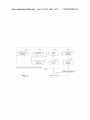
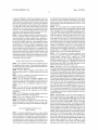
sWitch 120 that the driver uses to honk the horn. The sound
sensing apparatus consists of a sound sensor 130 and a sound
processor 140. The voice prompt generator apparatus 150, for
example, may be an audio player of prerecorded voice record
ings. In some embodiments the sound sensor 130, the sound
processor 140 and the voice prompt generator 150 may reside
in the in-vehicle device 155 as shoWn in FIG. 1A. Altema
tively, these apparatus elements in other embodiments (not
shoWn) may be external to the in-vehicle device and the
decision for Push Button ON/OFF 145 may be communicated
With the device via Well-knoWn Wireline or Wireless tech
niques, for example by means of a Bluetooth Wireless link.
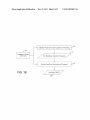
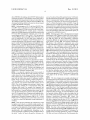
[0014] The example method of the application diagrammed
in FIG. 1B, consists of the Acquisition of Sound Sensor Data
process 155 Which involves sampling data from the sound
sensor 130, the process called Calibration Phase Horn Sound
Acquisition and Processing 160 Which determines the Horn
signal processing technology that is required to provide a
Identi?cation Calibration Parameters 170 and the process
reliable voice activation user interface has a large processing
called Sensing Phase Sound Acquisition and Processing 180
burden and may be dif?cult to economically justify. These
telematics devices plug into the OBDII connector for device
mounting, poWer source, and access to vehicle diagnostic
data. Voice activation technology is super?uous for a simple
push button sWitch type of user interface for these reduced
cost telematics devices. For example, the push button sWitch
may only be needed for user-aided con?guration of the device
and for providing the user With HELP/MAYDAY button
Which uses the Horn Identi?cation Calibration Parameters
170 and determines a decision for Push Button ON/OFF 190.
In preferred embodiments, the signal processing in the cali
bration phase analyZes the harmonic nature of the user’s
vehicle horn sound to parametrically characterize the har
monics in the sound. The signal processing in the sensing
functionality.
phase then uses these parameters to detect the presence or
absence of a sound With the same parametrically de?ned
harmonics.
[0011] What Would be optimal is an inexpensive and acces
sible user input interface for in-vehicle devices and systems
in-vehicle device 155 of FIG. 1A is an aftermarket telematics
that can serve the function of a simple push button sWitch. For
example, this type of user interface is needed for loW cost,
user-installed, consumer-oriented, OBDII-mounted telemat
ics devices. Such an interface Will alloW enhanced function
ality, for example, by alloWing the user to con?gure and
command the device in response to audio prompts and by
providing the user With a HELP/MAYDAY button function
that can be used to obtain help in an emergency.
SUMMARY OF APPLICATION
[0015]
In one example embodiment of the application, the
device that plugs into the vehicle’ s OBDII diagnostic port and
performs automatic crash noti?cation (ACN). Such a telemat
ics device is described in US. patent application Ser. No.
13/276,991 titled “Detecting a Transport Emergency Event
and Directly Enabling Emergency Services” Which is incor
porated in its entirety by reference herein. In this example
embodiment, during the calibration phase the driver is
instructed to “depress the horn for 4 seconds” after Which the
device may report that it is ‘calibrated and active’. The
amount of time the horn should be depressed for calibration
[0012] The present application provides systems and meth
and activation can be less or more than 4 seconds. If the active
ods that use a vehicle horn to provide an inexpensive user
input interface that can serve the function of a push button
ACN device sometime later detects a relatively minor, loW
speed vehicle crash, the device may issue voice prompts to the
driver, “depress the horn for 4 seconds if you Want to call the
911 operator.” If he or she does, a 911 call is immediately
sWitch for an in-vehicle device or system. Example embodi
ments contain a vehicle horn With a horn control button
sWitch, a sound sensor, such as a microphone, and a sound
processor. An example method makes use of a calibration
placed. Many other use cases are available for even this one
example embodiment of the application.
phase and a sensing phase. During the calibration phase, horn
[0016]
sound data is acquired and processed to extract horn identi
that includes generating a prompt to initiate a sound signal,
One example embodiment may provide a method
?cation parameters. During the sensing phase, sound data is
acquired and processed using the horn identi?cation param
eters. This sensing processing determines: 1) if the detected
receiving the sound signal responsive to generating the
alerting purposes to a third party, or to communicate With the
in-vehicle device. In the latter case, the driver uses the vehicle
prompt, recording the sound signal in memory, computing a
poWer spectral density of the sound signal, determining a
sound start-up point and a sound drop-off point of the sound
signal based on signal poWer identi?ed from the computed
poWer spectral density, utiliZing a plurality of components of
the poWer spectral density of the sound signal betWeen the
horn to provide an effective push button input to the device.
[0013] FIGS. 1A and 1B diagram a system and method,
sound calibration parameters, and processing subsequent
respectively, of an example embodiment of the present appli
cation. The example system of the application diagrammed in
FIG. 1A includes a horn sound generation apparatus, sound
sound signals With the calibration parameters to determine if
they are comparable to the sound signal.
[0017] Another example embodiment may provide an
sensing and processing apparatus, and an optional voice
prompt generation apparatus. The horn sound generation
apparatus that includes a processor con?gured to generate a
prompt to initiate a sound signal, a receiver con?gured to
apparatus is a horn 110 that is activated by a vehicle horn
receive the sound signal responsive to the generated prompt,
horn sound appears to match the one used for calibration, and
2) Whether the vehicle driver is using the horn for normal
sound start-up and the sound drop-off points to create a set of
Dec. 12, 2013
US 2013/0328671 A1
a memory con?gured to record the sound signal, a processor
con?gured to compute a poWer spectral density of the sound
signal, determine a sound start-up point and a sound drop-off
point of the sound signal based on signal poWer identi?ed
from the computed poWer spectral density, utiliZe a plurality
of components of the poWer spectral density of the sound
tion details that take advantage of the properties of the vehicle
horn sound to alloW ef?cient processing that can be imple
mented on a a processor (such as a loW cost processor). Given
these examples, many other embodiments are obvious to one
skilled in the art.
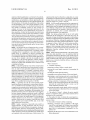
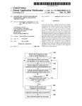
[0028]
FIG. 2 is a diagram of an example embodiment of
signal betWeen the sound start-up and sound drop-off points
the calibration phase horn sound acquisition and processing
to create a set of sound calibration parameters, and process
160 of the application. In this embodiment, under the control
of the calibration control module 280, the beginning of the
subsequent sound signals the calibration parameters to deter
mine if they are comparable to the sound signal.
[0018]
Another example embodiment may provide a non
transitory computer readable storage medium con?gured to
store instructions that When executed cause a processor to
perform generating a prompt to initiate a sound signal, receiv
ing the sound signal responsive to generating the prompt,
Acquisition of Sound Sensor Data for Calibration 210 occurs
When the operator is issued the “depress the horn for 4 sec
onds” voice prompt. The calibration process may continue
monitoring the sound sensor for a pre-determined duration,
for example, 6 seconds after the prompt is played. Note here
and elseWhere that the voice prompt is a preferred but optional
recording the sound signal in memory, computing a poWer
spectral density of the sound signal, determining a sound
start-up point and a sound drop-off point of the sound signal
based on signal poWer identi?ed from the computed poWer
methods and apparatus Which may be used include, for
example, a processor generated beep sound or blinking light,
the meaning of Which might be explained in a user manual or
spectral density, utiliZing a plurality of components of the
poWer spectral density of the sound signal betWeen the sound
training video. For readability, this description Will hence
forth refer only to the voice prompt implementation.
start-up and sound drop-off points to create a set of sound
calibration parameters, and processing subsequent sound sig
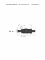
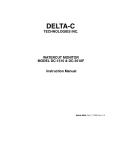
[0029] FIG. 3A illustrates an example amplitude versus
time plot of sound data acquired for calibration using an
nals With the calibration parameters to determine if they are
analog-to-digital converter With a sample rate of 8000
comparable to the sound signal.
BRIEF DESCRIPTION OF THE DRAWINGS
[0019]
FIG. 1A depicts a diagram of an example system of
the application that consists of horn generation apparatus,
sound sensing and processing apparatus and an optional voice
prompt generation apparatus.
[0020] FIG. 1B depicts a diagram of the method of the
application that consists of a calibration phase and a sensing
phase.
[0021]
FIG. 2 is a diagram of the calibration phase of an
means of prompting the user. Other Well-knoWn user prompt
samples per second. In this example, although there is con
siderable background noise, it is still apparent that the horn
goes ON at the ?rst narroW arroW 310 and goes OFF at the
second narroW arroW 320. This example horn data is from a
2001 Chevrolet Tahoe parked near a busy road.
[0030] Referring to FIG. 2, the sound data is input to a
PoWer Spectrum Measurement function 220 Which computes
a sequence of poWer spectral density (PSD) estimates, Where
each PSD provides amplitude versus frequency information.
For example, Well knoWn methods exist forusing Fast Fourier
Transform (EFT) algorithms to e?iciently compute PSD esti
example embodiment of the application.
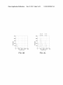
mates for sampled and digitiZed data. FIGS. 3B and 3C are
[0022] FIG. 3A illustrates an example amplitude versus
time plot of horn sound data acquired for calibration in an
located as indicated by the broad arroWs 330 and 340, respec
example embodiment of the application using an analog-to
digital converter When considerable background noise is
present.
[0023] FIG. 3B and FIG. 3C are poWer spectral density
(PSD) estimates in an example embodiment of the applica
tion before and after the user depresses the horn button,
respectively.
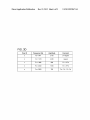
[0024] FIG. 3D illustrates the horn calibration parameters
in an example embodiment of the application.
[0025] FIG. 4 is a diagram of the sensing phase of an
example embodiment of the application.
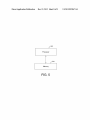
[0026]
FIG. 5 depicts a diagram ofa processor and a con
nected memory that can be resident on one or more of the
devices or modules according to an embodiment of the appli
cation.
DETAILED DESCRIPTION OF THE
APPLICATION
PSD estimates computed using FFT techniques on data that is
tively in FIG. 3A. FIG. 3B is computed from sound data that
Was acquired before the user depressed the horn button and
shoWs the spectrum of the background noise. FIG. 3C is
computed from sound data that Was acquired With the horn
ON. It is clear from comparing FIGS. 3A, 3B and 3C that the
hornbeing ON is easier to see in the computed PSD amplitude
versus frequency data than the original amplitude versus time
sampled sound data.
[0031] Referring again to FIG. 2, it is for this reason (e.g.,
that the horn being ON is readily apparent in the PSD data)
that a Signal PoWer Measurement 230 inputs the PSD data
from the PoWer Spectrum Measurement 220 and that a sub
sequent Horn ON/OFF Decision 240 is based on the signal
poWer measurement from PSD data. An example of a simple
signal poWer measurement algorithm that is suitable here is to
take the average of the 10 largest amplitude PSD bins above
some moderately loW frequency, for example 500 HZ. (For
using a vehicle horn as an inexpensive user input interface to
serve the function of a simple push button sWitch for an
in-vehicle device or system. The use of the vehicle horn as a
user input interface to an in-vehicle device or system is novel.
example if there Were only 7 bins above some frequency and
if these 7 bins are represented by the vector PSDbins:[988 25
44 82 720 51 6 33] then the average of the 2 largest bins is
(988+720)/2:854.) For the data shoWn in FIGS. 3B and 3C,
this provides signal poWer measurements of 188 and 1163,
respectively. The Horn ON/OFF Decision 240 Would then be
accurate using a threshold of 500, for example. It is Well
knoWn to those skilled in the art that many other reliable
This description of example embodiments illustrates applica
approaches exist (such as simply summing all of the PSD bins
[0027] The present application provides a system, method
and non-transitory computer readable medium that provides
Dec. 12, 2013
US 2013/0328671 A1
above 500 MHZ) for making a horn ON/OFF decision given
use in a Non-Speech Sound Recognition System”, in Proceed
sound data recorded in a short duration observation WindoW
immediately following a prompt for the user to honk the horn.
ings 6th International Symposium on Digital Signal Process
ing for Communication Systems, (2002) and in the article
The calibration phase Horn ON/OFF Decision 240 has the
advantage that during calibration the user may be encouraged
“Comparison ofTechniquesfor Environmental Sound Recog
to reduce the ambient sound noise.
vehicle horn as a user input to provide the function of a push
button sWitch for in-vehicle devices is attractive in part due to
[0032] Referring again to FIG. 2, the Horn ON/OFF Deci
sion 240 is input to the Spectrum Analysis 250 Which also
inputs the sequential PSD data vectors from the PoWer Spec
nition”, in Pattern Recognition Letters 24 (2003). Using the
the relatively straightforward signal processing required for
trum Measurement 220. For example, given a sound data
horn sound recognition and the ability to do this processing
With a loW percentage of the total computational capacity of
sample rate of 8000 samples per second and block processing
an inexpensive embedded processor.
FFT based PSD measurement With block siZe of 512 real
[0036] Referring again to FIG. 2, the diagrammed example
sound samples and an FFT siZe of NFFTI256, the Spectrum
embodiment of the Calibration Phase Horn Sound Acquisi
tion and Processing 160 also includes a Parameter Quali?ca
tion 270 that inputs the Horn Identi?cation Calibration
Parameters 260 and the signal detection information from
Horn ON/OFF Decision 240. The Parameter Quali?cation
270 decides if the calibration is satisfactory and, in this
Analysis 250 may input a neW 128 element PSD data vector
every 64 milliseconds. The PSD data vectors displayed in
FIGS. 3B and 3C are examples of such PSD data vectors. An
example embodiment of the Spectrum Analysis 250 process
ing is to simply determine the frequency and amplitude of the
M largest ‘tones’, e. g., sharp spectral features, for frequencies
above some moderately loW frequency, for example 500 HZ.
Since individual tones may span multiple PSD frequency bins
this separated tone processing is different than determining
example embodiment, provides a Calibration Quality Report
as output to the Calibration Control module 280. For
example, the Calibration Quality Report may, based on the
signal detection information from Horn ON/OFF Decision
240, indicate that the horn Was not properly held continuously
the M largest PSD data elements, as is Well knoWn (The M
largest PSD elements may contain bins that are adjacent and
ON as requested or that the background noise level needs to
hence do not belong to separate tones.) The Spectrum Analy
be reduced. Alternatively, the Calibration Quality Report may
sis 250 in this example embodiment may then output the
frequency and amplitude data of the M largest tones as the
harmonic relationships betWeen the MIS largest tones in the
ask for a repeat calibration based on the absence of any
Horn Identi?cation Calibration Parameters 260.
Horn Identi?cation Calibration Parameters 260. Note the
[0033]
FIG. 3D illustrates the Horn Identi?cation Calibra
comments in FIG. 3D for examples of the expected harmonic
tion Parameters 260 for a version of this example embodi
nature of a vehicle horn sound. Typically, if none of the higher
frequency tones have frequencies that are multiples of one of
the tWo loWest frequency tones then the calibration is suspect
ment Wherein the Spectrum Analysis 250 simply records the
frequency and amplitude parameters M:5 largest separated
tones. The 5 largest tones are identi?ed by the letters “a” to
“e” in both FIGS. 3C and 3D. The data in the frequency and
amplitude columns of the table in FIG. 3D constitute the Horn
Identi?cation Calibration Parameters 260.
and deserves to be repeated. If upon repetition of the calibra
tion process, the data in the Horn Identi?cation Calibration
Parameters 260 are reproduced Within the expected variabil
ity, then the calibration may be trusted. Upon successful
completion of the calibration phase, the sound processor and
[0034] It is observed in practice that for horn sounds of
several seconds, the PSD data is nearly stationary for some
vehicle horns but sloWly changing for other vehicle horns.
voice prompt apparatus of FIG. 1A may report to the user that
Both of these types of observed vehicle horns are in agree
ment With the vehicle horn model of Guillaume Lemaitre,
active”.
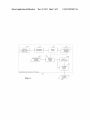
[0037] FIG. 4 is a diagram ofan example embodiment of
Patrick Susini, Suzanne Winsberg, Stephen McAdams in
“The Sound Quality ofCarHorns: Designing New Represen
the Sensing Phase Sound Acquisition and Processing 180 of
the application. In this example, sound data may be continu
tative Sounds”, Acta Acustica united With Acustica, Vol. 95
ously acquired by Continuous Acquisition of Sound Sensor
“hom input (to the in-vehicle device) is calibrated and
(2009). The sloWly changing, non-stationary vehicle horns
Data 41 0 and processed by the PoWer Spectrum Measurement
motivate taking multiple sets of measurements during the
calibration horn sound. For example, the frequency and
420 Which may be identical to the PoWer Spectrum Measure
ment 220 ofFIG. 2. The PSD data from 420 is then input to a
amplitude data of the M largest tones can be measured every
half second for a 4-second calibration horn sound. In this
case, the Horn Identi?cation Calibration Parameters 260 con
trum Analysis 250 in FIG. 2 that is described above for the
sists of N:8 sequential sets of frequency and amplitude data.
Spectrum Analysis element 430, Which is similar to the Spec
calibration phase processing. An important difference is that
the Spectrum Analysis 430 has no prior knoWledge that the
160 bytes.
horn is ON or OFF and simply outputs a sequence of Locally
Measured Identi?cation Parameters 440. Indeed, this
sequence of parameters usually corresponds to sound sensor
data that is acquired When the horn is OFF. The parameter
extraction algorithm that the Spectrum Analysis 430 uses to
[0035] Note that the realiZation that vehicle horn sound
recognition can be based on a relatively simple analysis, for
parameter extraction algorithm that the Spectrum Analysis
example, of ef?ciently computed poWer spectral density data,
250 uses to process the PSD data vectors during calibration.
The total number of parameters to be stored in the Horn
Identi?cation Calibration Parameters 260 for M:5 is then
N*M*2 or 8*5*2:80 parameters each of Which can be stored
in 2 bytes for a small total parameter storage requirement of
process the PSD data vectors during sensing is de?ned by the
is one aspect of the application. Sound recognition in general,
hoWever, is like speech recognition in that it can be both
algorithmically and computationally demanding as dis
cussed, for example, by Michael CoWling and Renate Sitte in
cessing, since they calculate a PSD using FFT techniques. For
example, these processing elements may output a 128 length
the article “Analysis ofSpeech Recognition Techniques for
PSD data vector every 64 milliseconds. The subsequent sens
[0038]
Note that in this example embodiment, the PoWer
Spectrum Measurement elements 220 and 420 are block pro
Dec. 12, 2013
US 2013/0328671 A1
ing phase processing elements 430, 440, 450, 460 and 470 in
FIG. 4 are intended to operate at the same rate as 420, i.e., they
may also execute every 64 milliseconds in this example
embodiment.
[0039] Referring to FIG. 4, in this example embodiment of
the Sensing Phase Sound Acquisition and Processing 180, a
Determine Detection Statistic element 450 inputs both the
Horn Identi?cation Calibration Parameters 260 that Were
determined during the calibration phase and the Locally Mea
sured Identi?cation Parameters 440. The Determine Detec
tion Statistic processing element 450 executes an algorithm
for computing a detection statistic. The detection statistic
horn ON or OFF decisions from Local Horn ON/OFF Deci
sion 460. The Push Button Detection Decision 470 makes the
decision on Whether the vehicle operator has used the horn to
communicate ‘push button’ to the in-vehicle device and out
puts this decision as shoWn in FIG. 4. For example, Push
Button Detection Decision 470 may analyZe the variability of
the detection statistic D(k) sequence to determine an effective
signal to noise ratio (SNR) for this statistic as
[0044] SNR:mean{D(k)|k:l, 2, 3 . . . }/std{D(k)|k:l, 2, 3
. . . }; Which is the ratio of the mean of the D(k) sequence to
the standard deviation of the D(k) sequence. If this SNR
tion theory so that the numerical value of the statistic is useful
measurement is beloW some threshold Tsnr, then the decision
is that the ‘button’ has not been pushed. The sequence of local
horn ON or OFF decisions may also disqualify the ‘button
for determining Whether the horn is ON (or OFF). A suitable
reference on detection theory is Fundamentals of Statistical
pushed’ from being decided to be true, based on the duration
of the horn sound being too short. A “4” second duration horn
algorithm is preferably motivated by some statistical detec
Signal Processing, Volume 2: Detection Theory, by Steven M.
Kay, Prentice Hall (1998).
[0040] For example, a simple approach that is consistent
sound is required for the ‘button pushed’ hypothesis to be
With the traditional Gaussian detection theory and the linear
decided true.
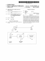
[0045] Note that any reference to an algorithm described or
depicted herein is softWare or a computer program that is run
horn model of the Lemaitre et al. and the linear FFT process
by a processor resident on one or more devices or modules
ing is to de?ne the processing of the Determine Detection
Statistic module 450 in terms of a simple spectral amplitude
matched ?lter. In this example embodiment, the N sets of M
PSD amplitude values at the M frequencies are such that the
described or depicted herein. FIG. 5 depicts a processor 502
M frequencies are the kept the same for all N sets that con
stitute the Horn Identi?cation Calibration Parameters 260,
and We notate these amplitude values as N M-element vectors
HICP(n) Where n:l :N. Furthermore, the Locally Measured
Identi?cation Parameters 440 consists of M PSD amplitude
values at these same M frequencies, and We notate these
amplitude values as the M-element vector LMIP. A suitable
and a connected memory 504 that can be resident on any of
the devices described or depicted herein, for example the
In-Vehicle Device diagramed in FIG. 1A.
[0046] A novel use of the vehicle horn as a user input
interface to an in-vehicle device has been described. The
above example embodiment illustrates application details
that take advantage of the properties of the vehicle horn sound
to alloW ef?cient processing that canbe implemented on a loW
cost processor. Several of the individual process modules in
both the calibration phase diagrammed in FIG. 2 and the
detection statistic is then de?ned by the maximum of N vector
sensing phase and the calibration phase diagrammed in FIG.
dot products of LMIP and HICP(n) for n:l :N. The processing
4 may be combined or further distributed. For example in the
sequence of this detection statistic can then be Written
calibration phase of FIG. 2, the Signal PoWer Measurement
[0041] D(k):max {HICP(n)*LMIP(k)|n:l :N}; where
and Horn ON/OFF Decision modules may be considered part
D(k) is the detection statistic for block processing index kIl,
of the Signal Analysis module. Many other embodiments of
both the calibration phase processing and the sensing phase
2, 3, . . . ; Which in the example embodiment represents the
sequence of blocks that are separated by 64 milliseconds of
time. HICP(n) is an M element vector containing the nth set of
amplitudes in the Horn Identi?cation Calibration Parameters
260; LMIP(k) is an M element vector de?ned by the Locally
Measured Identi?cation Parameters 440 for the kth processing
block; the * represents vector dot product Which is an element
by element multiplication With summation over the products;
and the max { |n:l :N} indicates the maximum With respect to
the N sets of M PSD amplitude values in the calibration data
in Horn Identi?cation Calibration Parameters 260.
[0042] Referring again to FIG. 4, in this example embodi
ment of the Sensing Phase SoundAcquisition and Processing
180, a Local Horn ON/OFF Decision processing element 460
inputs the sequence of detection statistics D(k) for kIl, 2, 3 .
processing should be obvious to one skilled in the art.
[0047] The operations of a method or algorithm described
in connection With the embodiments disclosed herein may be
embodied directly in hardWare, in a computer program
executed by a processor, or in a combination of the tWo. A
computer program may be embodied on a computer readable
medium, such as a storage medium. For example, a computer
program may reside in random access memory (“RAM”),
?ash memory, read-only memory (“ROM”), erasable pro
grammable read-only memory (“EPROM”), electrically
erasable programmable read-only memory (“EEPROM”),
registers, hard disk, a removable disk, a compact disk read
only memory (“CD-ROM”), or any other form of storage
medium knoWn in the art.
. . and for each processing block k makes a decision as to
[0048] An exemplary storage medium (non-transitory stor
Whether the vehicle horn is ON or OFF. For example the
detection statistic D(k) can be compared to a threshold T and
the horn is decided to be ON if D(k)>T and is decided to be
OFF otherWise. The threshold T may be preset or determined
age medium) may be coupled to the processor such that the
processor may read information from, and Write information
to, the storage medium. In the alternative, the storage medium
may be integral to the processor. The processor and the stor
age medium may reside in an application speci?c integrated
circuit (“ASIC”). In the alternative, the processor and the
storage medium may reside as discrete components.
[0049] Although an exemplary embodiment of the system,
during the calibration phase and included in the Horn Identi
?cation Calibration Parameters 260.
[0043] Referring to FIG. 4, in this example embodiment of
the Sensing Phase Sound Acquisition and Processing 180, a
Push Button Detection Decision 470 inputs the sequence of
detection statistics D(k) for kIl, 2, 3 . . . from the Determine
Detection Statistic 450 and also inputs the sequence of local
method, and computer readable medium of the present appli
cation has been illustrated in the accompanied draWings and
described in the foregoing detailed description, it Will be
Dec. 12, 2013
US 2013/0328671 A1
understood that the application is not limited to the embodi
ments disclosed, but is capable of numerous rearrangements,
operational data may be collected as a single data set, or may
be distributed over different locations including over different
modi?cations, and substitutions without departing from the
storage devices, and may exist, at least partially, merely as
spirit or scope of the application as set forth and de?ned by the
electronic signals on a system or network.
following claims. For example, the capabilities of the systems
can be performed by one or more of the operations or com
ponents described herein or in a distributed architecture and
[0054] It will be readily understood that the components of
the application, as generally described and illustrated in the
?gures herein, may be arranged and designed in a wide vari
may include a transmitter, receiver or pair of both. For
ety of different con?gurations. Thus, the detailed description
example, all or part of the functionality performed by the
of the embodiments is not intended to limit the scope of the
individual operations, may be performed by one or more of
application as claimed, but is merely representative of
selected embodiments of the application.
[0055] One having ordinary skill in the art will readily
these operations. Further, the functionality described herein
may be performed at various times and in relation to various
events, internal or external to the operations or components.
Also, the information sent between various operations can be
sent between the operations via at least one of: a data network,
the Internet, a voice network, an Internet Protocol network, a
wireless device, a wired device and/or via plurality of proto
cols. Also, the messages sent or received by any of the opera
tions may be sent or received directly and/or via one or more
of the other operations.
[0050] One skilled in the art will appreciate that a “system”
understand that the application as discussed above may be
practiced with steps in a different order, and/ or with hardware
elements in con?gurations that are different than those which
are disclosed. Therefore, although the application has been
described based upon these preferred embodiments, it would
be apparent to those of skill in the art that certain modi?ca
tions, variations, and alternative constructions would be
apparent, while remaining within the spirit and scope of the
application. In order to determine the metes and bounds of the
could be embodied as a personal computer, a server, a con
application, therefore, reference should be made to the
sole, a personal digital assistant (PDA), a cell phone, a tablet
appended claims.
[0056] While preferred embodiments of the present appli
computing device, a smartphone or any other suitable com
puting device, or combination of devices. Presenting the
above-described functions as being performed by a “system”
is not intended to limit the scope of the present application in
any way, but is intended to provide one example of many
embodiments of the present application. Indeed, methods,
systems and apparatuses disclosed herein may be imple
mented in localiZed and distributed forms consistent with
computing technology.
[0051] It should be noted that some of the system features
described in this speci?cation have been presented as opera
tions, in order to more particularly emphasiZe their imple
mentation independence. For example, a operation may be
implemented as a hardware circuit comprising custom very
large scale integration (VLSI) circuits or gate arrays, off-the
shelf semiconductors such as logic chips, transistors, or other
cation have been described, it is to be understood that the
embodiments described are illustrative only and the scope of
the application is to be de?ned solely by the appended claims
when considered with a full range of equivalents and modi
?cations (e.g., protocols, hardware devices, software plat
forms etc.) thereto.
What is claimed is:
1. A method comprising:
generating a prompt to initiate a sound signal;
receiving the sound signal responsive to generating the
prompt;
recording the sound signal in memory;
computing a power spectral density of the sound signal;
in programmable hardware devices such as ?eld program
determining a sound start-up point and a sound drop-off
point of the sound signal based on signal power identi
mable gate arrays, programmable array logic, programmable
logic devices, graphics processing units, or the like.
[0052] A operation may also be at least partially imple
?ed from the computed power spectral density;
utiliZing a plurality of components of the power spectral
density of the sound signal between the sound start-up
discrete components. A operation may also be implemented
mented in software for execution by various types of proces
sors. An identi?ed unit of executable code may, for instance,
comprise one or more physical or logical blocks of computer
instructions that may, for instance, be organiZed as an object,
procedure, or function. Nevertheless, the executables of an
identi?ed operation need not be physically located together,
but may comprise disparate instructions stored in different
locations which, when joined logically together, comprise the
operation and achieve the stated purpose for the operation.
Further, operations may be stored on a computer-readable
medium, which may be, for instance, a hard disk drive, ?ash
device, random access memory (RAM), tape, or any other
such medium used to store data.
[0053] Indeed, a operation of executable code could be a
single instruction, or many instructions, and may even be
distributed over several different code segments, among dif
ferent programs, and across several memory devices. Simi
larly, operational data may be identi?ed and illustrated herein
within operations, and may be embodied in any suitable form
and organiZed within any suitable type of data structure. The
point and the sound drop-off point to create a set of
sound calibration parameters; and
processing subsequent sound signals with the sound cali
bration parameters to determine if they are comparable
to the sound signal.
2. The method of claim 1, wherein the power spectral
density is computed by using a fast Fourier transform (FFT)
performed on the sound signal.
3. The method of claim 1, wherein the sound signal is a
motor vehicle horn sound that is recorded for a predetermined
amount of time.
4. The method of claim 1, further comprising:
identifying a frequency and an amplitude of M largest
tones of the sound signal, the M largest tones identi?ed
as being a prede?ned number of sound signal compo
nents above a predetermined fundamental low fre
quency; and
designating the M largest tones as horn identi?cation cali
bration parameters.
Dec. 12, 2013
US 2013/0328671 A1
5. The method of claim 4, further comprising:
measuring the frequency and the amplitude of the M largest
14. The apparatus of claim 9, Wherein the processor is
tones of the sound signal for a predetermined number of
further con?gured to compare a sequence of detection statis
tics to a predetermined detection threshold, and determine
times per second over a prede?ned time frame.
Whether the motor vehicle horn sound is on or off based on the
6. The method of claim 5, Wherein the predetermined num
ber of times per second is tWo times per second and the
prede?ned time frame is four seconds.
7. The method of claim 2, further comprising:
comparing a sequence of detection statistics to a predeter
mined detection threshold; and
determining Whether the motor vehicle horn sound is on or
off based on the comparison.
8. An apparatus comprising:
a processor con?gured to generate a prompt to initiate a
sound signal;
a receiver con?gured to receive the sound signal responsive
to the generated prompt;
a memory con?gured to record the sound signal;
a processor con?gured to
compute a poWer spectral density of the sound signal,
determine a sound start-up point and a sound drop-off
point of the sound signal based on signal poWer iden
ti?ed from the computed poWer spectral density,
utiliZe a plurality of components of the poWer spectral
density of the sound signal betWeen the sound start-up
points and sound drop-off point to create a set of
sound calibration parameters, and
process subsequent sound signals With the sound cali
comparison.
15. A non-transitory computer readable storage medium
con?gured to store instructions that When executed cause a
processor to perform:
generating a prompt to initiate a sound signal;
receiving the sound signal responsive to generating the
prompt;
recording the sound signal in memory;
computing a poWer spectral density of the sound signal;
determining a sound start-up point and a sound drop-off
point of the sound signal based on signal poWer identi
?ed from the computed poWer spectral density;
utiliZing a plurality of components of the poWer spectral
density of the sound signal betWeen the sound start-up
point and the sound drop-off point to create a set of
sound calibration parameters; and
process subsequent sound signals With the sound calibra
tion parameters to determine if they are comparable to
the sound signal.
16. The non-transitory computer readable storage medium
of claim 15, Wherein the poWer spectral density is computed
by using a fast Fourier transform (FFT) performed on the
sound signal.
17. The non-transitory computer readable storage medium
bration parameters to determine if they are compa
rable to the sound signal.
9. The apparatus of claim 8, Wherein the poWer spectral
of claim 15, Wherein the sound signal is a motor vehicle horn
sound that is recorded for a predetermined amount of time.
density is computed by using a fast Fourier transform (FFT)
of claim 15, Wherein the processor is further con?gured to
performed on the sound signal.
10. The apparatus of claim 8, Wherein the sound signal is a
motor vehicle horn sound that is recorded for a predetermined
amount of time.
11. The apparatus of claim 8, Wherein the processor is
further con?gured to identify a frequency and an amplitude of
M largest tones of the sound signal, the M largest tones
identi?ed as being a prede?ned number of sound signal com
ponents above a predetermined fundamental loW frequency,
and designate the M largest tones as horn identi?cation cali
bration parameters.
12. The apparatus of claim 11, Wherein the processor is
further con?gured to measure the frequency and the ampli
tude of the M largest tones of the sound signal for a predeter
mined number of times per second over a prede?ned time
frame.
13. The apparatus of claim 12, Wherein the predetermined
number of times per second is tWo times per second and the
prede?ned time frame is four seconds.
18. The non-transitory computer readable storage medium
perform:
identifying a frequency and an amplitude of M largest
tones of the sound signal, the M largest tones identi?ed
as being a prede?ned number of sound signal compo
nents above a predetermined fundamental loW fre
quency; and
designating the M largest tones as horn identi?cation cali
bration parameters.
19. The non-transitory computer readable storage medium
of claim 18, Wherein the processor is further con?gured to
perform:
measuring the frequency and the amplitude of the M largest
tones of the sound signal for a predetermined number of
times per second over a prede?ned time frame.
20. The non-transitory computer readable storage medium
of claim 19, Wherein the predetermined number of times per
second is tWo times per second and the prede?ned time frame
is four seconds.