1
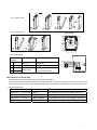
Fig.1 open the cover
1
4
3
2
Fig.4 close the cover
Fig.2 wall plate
28.00
3.00
55.00
4.50
8.00
45.00
6
5
7
60.00
jump selection
Fig.3 wiring diagram
J6 J5
J6 J5
400ppm
Connection
Function
Electrical Data
J6 J5
1200ppm
J6J5
800ppm
J6 J5
1600ppm
Terminal
1
G+
Power (+)
24VAC/VDC +
2
G0
Power ground (-)
24VAC/VDC
4
Ventilator
5
Common
Relay output
Common
ON
Line
Voltage
<240VAC/30VDC 3A switching
24VAC
Transformer
1 2
4 5
current (resistance load)
Select CO2 level to Control the Relay
The CO2 level for control the relay turning on has been set to 1200ppm.
If you need to change the CO2 level, open the cover after switch off, you may see two jumpers (J4 and J5) on the top of the
circuit board and under the CO2 module. Take off the CO2 module, you can select the CO2 level to control the relay on /off by
jumpers as below table.
Jumper
CO2 level
Relay turns on /turns off
J4-disconnect;
J5-disconnect
800ppm
CO2>900ppm,the relay on; CO2 <700ppm,the relay off
J4-connect;
J5-disconnect
1000ppm
CO2>1100ppm, the relay on; CO2 <900ppm, the relay off
J4-disconnect;
J5-connect
1200ppm (default)
CO2>1300ppm, the relay on; CO2 <1100ppm, the relay off
J4-connect;
J5-connect
1400ppm
CO2>1500ppm, the relay on; CO2 <1300ppm, the relay off
2