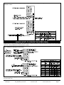
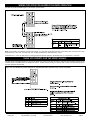
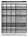
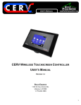
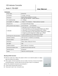
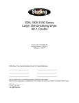
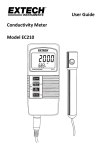
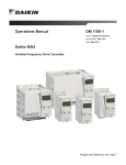
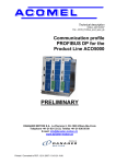
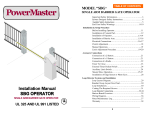
1
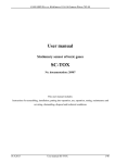
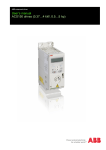
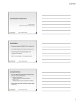
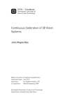
4510 Helgesen Drive, Madison, WI 53718 (608) 221-4499, (800) 627-4499, Fax: (608) 221-2824 [email protected] www.renewaire.com Factory-Installed Variable Frequency Drives (VFD) in RenewAire (ERV) Ventilators RISK OF FIRE, ELECTRIC SHOCK, OR INJURY. OBSERVE ALL CODES AND THE FOLLOWING: 1. Before servicing or cleaning the unit, switch power off at disconnect switch or service panel and lock-out/tag-out to prevent power from being switched on accidentally. More than one disconnect switch may be required to de-energize the equipment for servicing. 2. This installation manual shows the suggested installation method. Additional measures may be required by local codes and standards. 3. Installation work and electrical wiring must be done by qualified professional(s) in accordance with all applicable codes, standards and licensing requirements. 4. Any structural alterations necessary for installation must comply with all applicable building, health, and safety code requirements. 5. This unit must be grounded. 6. Use the unit only in the manner intended by the manufacturer. If you have questions, contact the manufacturer. 7. When cutting or drilling into unit, wall or ceiling, do not damage electrical wiring and other hidden utilities. 8. Do not re-wire the VFD(s) to control more than one motor per VFD. 9. Do not operate the motors in this unit above the motor’s rated full load amps (FLA) as indicated on the unit’s nameplate. NOTE: VFD(s) in this unit can be operated in many ways. This Manual provides only an outline of common methods. HOW TO USE THIS MANUAL IN THIS MANUAL YOU WILL FIND: • Orientation – basic concepts including ON and SPEED signals, Parameters and Keypad. • Simple Startup – how to make the unit run temporarily for testing and start-up. • Control Connections – examples of control system wiring connections to the ERV and the VFD(s). • VFD Parameters – information about the most commonly used Parameters • Scaling and Response to Analog Inputs – step-by-step approach to scaling VFD speed so that it responds correctly to an analog input from the external control system. FOR COMPLETE ERV INSTALLATION YOU WILL ALSO NEED: • Standard Installation and Operation Manual for the ERV – physical installation and duct connection, maintenance procedures, etc. • Supplemental Wiring Schematic Manual – complete unit wiring diagrams. • Short Form User’s Manual ACS320 – ABB’s user’s/installer’s manual. More detailed information is available online in the Document Library at www.abb.com/drives. VFD Addendum 138291_000 DO NOT OPERATE VFD IN CONDITIONS OUTSIDE OF TEMPERATURE LIMITS: The manufacturer’s ambient temperature limits for the VFDs are 14 to 122 °F. It is not recommended that the VFDs be used under conditions above or below these temperature limits. Operate outdoor ERV units continuously if outdoor design conditions are not within the VFD operating temperature range or make other provisions to bring the VFD operating condition into the acceptable ambient temperature range. RenewAire commercial ERVs are VFD ready, in extreme climates consider field installing VFDs in a climate controlled indoor electrical cabinet. ORIENTATION “ON” AND “SPEED” SIGNALS VFD operation in this unit is dependent on two signals: an ON signal and a SPEED (or REFERENCE) signal. The sources and types of these signals can vary. If the ERV is equipped with dampers the ON signal to the VFD comes from the end switch on the damper. If the ERV is not equipped with dampers, the ON signal comes from an external control connected directly to the VFD. When an ON signal is received by the VFD, it starts the motor. The VFD then operates the blower at the speed established by the SPEED signal. The SPEED signal is often provided by an external control, but in some applications “pre-set” speeds are set inside the VFD and are selected by external switches or relays. PRINCIPLES OF EXTERNAL CONTROL This ERV can be operated by various external control devices including remote switch or relay, digital time clock with relay, occupancy sensor with relay, and carbon dioxide sensor with relay and analog output. These devices are commonly known as 2-wire, 3-wire, and 4-wire devices. A Building Management System (BMS) can control this ERV through relay contacts and with 0-10vdc or 4-20mA analog inputs. The external control devices can be connected to this ERV to operate each blower independently or for one blower to act as leader and the other blower to act as follower. In leader-follower mode, a single external switch or relay calls for operation and the leader VFD sets SPEED to internal presets, or in response to an analog input signal. The follower VFD then operates at either exactly the same speed, at an offset above or below the leader’s speed, or at a scaled speed. The VFD’s are pre-programmed at the factory so only a few parameters need change for a specific installation. CONNECTING EXTERNAL CONTROLS If this ERV is equipped with damper(s), the ON signal is connected to the terminal strip in the electrical enclosure (“E-box”). If this ERV is not equipped with damper(s), and has 2 VFDs, the ON signal is connected directly to the VFDs. The SPEED signals are always connected directly to the VFD(s). Due to continuing product development, specifications are subject to change without notice. © 2012 RenewAire LLC VFD_Addendum_Jan12.indd Revised 01/2012 www.renewaire.com Page 1 SIMPLE STARTUP WIRE ROUTING Route input power cables, motor cables and control cables separately to decrease electromagnetic interference caused by the rapid changes in the drive output voltage. Where control cables must cross power cables make sure that they are arranged at an angle as near to 90 degrees as possible. See the ABB VFD manual for more detailed wire routing instructions. Power cables and control cables can be brought into the bottom of the electrical box attached to the ERV unit or through the bottom of the unit itself. There are plugged holes to run control wires and power wires between the electrical box and the unit interior, marked on the interior of the ERV unit and another plugged hole in the unit compartment divider to run wires to VFDs in the other airstream compartment if needed. In some configurations the VFD and/or VFD protective guard may need to be removed to access the control wire hole plug to run wires. A label is located in the ERV on the left interior wall indicating the power and control wire hole plug locations. Bring wires out from the top or bottom of the VFD mounting bracket and not through the mounting bracket window when routing wires if the VFD is mounted over the hole plug. After the wires are run, apply caulk around the wires at wire bushings used between the electrical box and ERV unit and between compartments in the unit to prevent air leakage between these compartments. PURPOSE OF PROVIDED KEYPAD Each VFD has a keypad which is accessible at the E-box while the unit is operating. You can check the status of the VFD at the keypad, and make changes to the VFD parameters at the keypad. You can manually control the VFD from the keypad during start-up and commissioning. (VFD is factory programmed to cover most needs but some parameters will need to be set to interact with the external control system.) Access the keypad(s) through the removable cover to the E-box. ABB Key Pad Buttons 230V Power Supplies ERVs rated for 208-230VAC power supplies are shipped with VFD parameters set for 208V operation. For 230VAC operation, change the following Parameters: 2003 MAX CURRENT Change to match the motor FLA for 230V, as listed on the unit nameplate. 9905 MOTOR NOM VOLT Change from 208V to 230V. 9906 MOTOR NOM CURR Change to match the motor FLA for 230V, as listed on the unit nameplate. TO START ERV 1) Turn off power to the ERV at its Disconnect Switch. • Make sure the ERV is wired to provide an ON signal. (See Control Wiring Schematics later in this Manual.) You may need to install a temporary jumper at the ERV or VFD lowvoltage terminal strip. • VFDs are set at the factory to respond to the keypad. If an external controller providing an analog input is connected to the VFD, you may want to temporarily disconnect it. • Close ERV doors and main cover for the E-box; leave keypads accessible. 2) Turn on power to the ERV at its Disconnect Switch. • Wait for keypad display to appear. 3) For each VFD: • Press the HAND button on the keypad. Motor should start running at about 425 RPM. • Use the UP/DOWN buttons to set motor speed as desired. Confirm the motor amps are no greater than the motor FLA as listed on the unit nameplate. 4) To transfer control of the VFD to a control system: • Press the OFF button on the keypad. Motor should stop running. • Change the VFD parameters as required for the specific controls system (see “Control Connections” and “VFD Parameters”, below, for examples; see also the ABB Manuals.) • Press the AUTO switch on the keypad. MOTOR PROTECTION BY THE VFD(s) Up/Down Buttons Softkey Each VFD in this unit protects one motor against overload. It is critical that the VFD be properly set at the Full Load Amps (FLA) of the motor. The following Parameters must be set correctly and individually for each VFD to match the characteristics of the motor attached to it: 2003 MAX CURRENT 9905 MOTOR NOM VOLT 9906 MOTOR NOM CURR 9909 MOTOR NOM POWER These parameters are set at RenewAire to match the motor controlled by the VFD. In most cases they should not be changed. Softkey “Auto” “OFF” Help Key “Hand” The function of each Softkey changes and is shown just above the Softkey in the display. VFD Addendum 138291_000 Due to continuing product development, specifications are subject to change without notice. © 2012 RenewAire LLC VFD_Addendum_Jan12.indd Revised 01/2012 www.renewaire.com Page 2 Capacitors in VFDs retain Charge Allow 2 minutes after shutting off power to the VFDs to allow the capacitors in the VFD to fully discharge. Do not connect or disconnect wires at the VFD without waiting 2 minutes. CONTROL CONNECTIONS “ON” SIGNAL CONNECTIONS If the ERV is equipped with Damper(s) and/or with just one VFD, the ON Signal control wires are connected to the low-voltage terminal strip in the ERV E-box. See Fig. 1. Install a jumper between terminals 2 and 3 to use the ERV’s on-board 24VAC power. Do this when the external control(s) have isolated contacts that don’t provide any voltage, as in the top two examples. Make no connections between terminals 1&2 and terminals 3-5 if the external control has a voltage output to provide the ON signal. This voltage must be 24VAC. With ERVs equipped with no dampers and 2 VFDs, the ON signal control wires are connected directly to the VFD. See Fig. 2 & 3. “SPEED” SIGNAL CONNECTIONS Any SPEED Signal connections are made directly to the VFD (see Figures 4, 6 & 7). The VFDs can accept 4-20mA or 0-10vdc analog control signals to operate at varying speeds. The VFDs also can accept momentary-contact inputs to operate at up to three preset speeds. VFD Parameters must be properly set to accept and act on Speed signals. Wiring for analog control signals should be twisted-pair, single- or double-shielded cable, with shield (and drain if provided) grounded at only one end of the cable. LEADER-FOLLOWER CONNECTIONS ON and SPEED signals can be passed from the LEADER VFD to a FOLLOWER VFD. See Figures 3 & 5. VFD Addendum 138291_000 Due to continuing product development, specifications are subject to change without notice. © 2012 RenewAire LLC VFD_Addendum_Jan12.indd Revised 01/2012 www.renewaire.com Page 3 Fig. 1: Connection of ON signals to low-voltage terminal strip in ERV E-box. Fig. 2 (ERVs with 2 VFDs and NO Dampers only): Separate ON Signals connected to each VFD. VFD Addendum 138291_000 Due to continuing product development, specifications are subject to change without notice. © 2012 RenewAire LLC VFD_Addendum_Jan12.indd Revised 01/2012 www.renewaire.com Page 4 Fig. 3 (ERVs with 2 VFDs and NO Dampers only): ON Signal connected directly to one VFD, passed to second VFD from terminals 17 & 19. ANALOG INPUTS TO PROVIDE THE SPEED SIGNAL Analog inputs are connected to terminals 2-4 as shown below. It may be necessary to scale the response of the VFD to the analog SPEED signal. See “Scaling and Response to VFD Parameters”, below. Fig. 4: Examples of Analog Input Connections. NOTE: All wiring for analog signals connected to the VFDs should be double- or single-shielded twisted-pair cable. Ground the shield at one end of the cable only. VFD Addendum 138291_000 Due to continuing product development, specifications are subject to change without notice. © 2012 RenewAire LLC VFD_Addendum_Jan12.indd Revised 01/2012 www.renewaire.com Page 5 WIRING TWO VFDS FOR LEADER-FOLLOWER OPERATION One VFD can provide the SPEED signal to a second VFD, as shown below. Fig. 5: Leader-Follower Connection. NOTE: Parameters 1501 and 1502 can be used to scale the Analog Output of the Leader VFD in order to offset or correct the speed of the Follower VFD. NOTE: If the FA VFD is controlled by an analog input signal, it is likely that the FA VFD’s response to the analog input will need to be scaled, using parameters 1104, 1105, 1301 and 1302. See “Scaling and Response to VFD Parameters”, below. If both VFDs are to run at the same speed, no scaling parameters need be applied to the EA VFD since it is controlled as a “Follower”. USING VFD PRESETS FOR THE SPEED SIGNALS The VFD can be programmed with 3 pre-set speeds. Momentary contact switches can then be used to direct the VFD to operate at one of those speeds. See ABB manuals for additional options. Leader-follower wiring can also be used to make a second VFD operate at the same speed as the first VFD. Fig. 6: Use of 2 Momentary-contact Switches to command the VFD to operate at any of 3 pre-set speeds. VFD Addendum 138291_000 Due to continuing product development, specifications are subject to change without notice. © 2012 RenewAire LLC VFD_Addendum_Jan12.indd Revised 01/2012 www.renewaire.com Page 6 USE WITH A CO2 CONTROLLER The example below corresponds to the example in the section “Scaling and Response to Analog Inputs”. The scaling parameters for the FA VFD in your application are likely to be different. Fig. 7: Example of Operation of 2 VFDs by a CO2 Controller. If both VFDs are to run at the same speed, no scaling parameters need be applied to the EA VFD in this example since it is controlled as a “Follower”. If it is desired that the VFDs should shut off when CO2 levels drop below a setpoint, connect the Normally Open contacts of the CO2 controller (terminals 3&4) to terminals 9 & 12 of the FA VFD. Adjust the operating parameters of the CO2 controller to set the relay setpoint. USE WITH A BUILDING MANAGEMENT SYSTEM The ABB ACS320 drive can be connected to an external control system via embedded fieldbus. The embedded fieldbus supports Modbus RTU, BACnet®, Metasys® N2 and APOGEE® FLN Protocols. See the ABB ACS320 Drives User’s Manual for details on connecting to an external control system. VFD Addendum 138291_000 Due to continuing product development, specifications are subject to change without notice. © 2012 RenewAire LLC VFD_Addendum_Jan12.indd Revised 01/2012 www.renewaire.com Page 7 VFD PARAMETERS VFD PARAMETER OVERVIEW “VFD Parameters” are instructions that the Variable Frequency Drives follow. They can be adjusted by using the keypads on the VFDs. In some control configurations, they will need to be changed from the settings as shipped in the unit to interface with your control system. To view the VFD’s Parameters from the keypad, press the MENU softkey. Press up/down arrows to highlight PARAMETERS, then select it by pressing the ENTER softkey. TO VIEW ALL VFD PARAMETERS VFD must be powered up – something will be showing on the LED display. If EXIT is displayed above the left softkey, press softkey repeatedly until MENU appears above the right softkey. Press the MENU softkey. Use the UP/DOWN arrows to scroll the display until PARAMETERS is selected, then press the ENTER softkey. You will see a numbered list of Parameter “groups” – those numbers are the first two digits of the Parameters in each group. Press the SEL softkey to view all the Parameters in each Group. Use the UP/DOWN buttons to scroll through the parameters. As each Parameter is selected, its value will be displayed. TO CHANGE VFD PARAMETERS Select the Parameter you want to edit (see above). Press the EDIT softkey. Use the UP/DOWN arrows to scroll through the available settings for that Parameter. Press the SAVE softkey to set the Parameter to the selected value. TO VIEW ONLY CHANGED VFD PARAMETERS If EXIT is displayed above the left softkey, press softkey repeatedly until MENU appears above the right softkey. Press the MENU softkey. Use the UP/DOWN arrows to scroll the display until CHANGED PAR is selected, then press the ENTER softkey. All Parameters that have been changed from the HVAC Application Macro default values are displayed. Use the UP/DOWN buttons to view them all. VFD Addendum 138291_000 Due to continuing product development, specifications are subject to change without notice. © 2012 RenewAire LLC VFD_Addendum_Jan12.indd Revised 01/2012 www.renewaire.com Page 8 SUMMARY TABLE OF COMMONLY USED PARAMETERS Note: Parameters not listed in this Table are shipped in ABB’s defaults for the HVAC Application Macro. * by parameter number indicates it is not visible in Short View. Name/Selection 9902 APPLIC MACRO ABB HVAC Default HVAC Settings as Shipped BY RenewAire HVAC FUNCTION Pressing SAVE softkey when USER 1 LOAD is selected returns the VFD to the parameters as shipped from RenewAire. Pressing SAVE softkey when HVAC DEFAULT is selected returns the VFD to the ABB defaults. 9901 LANGUAGE ENGLISH ENGLISH (AM) Sets language displayed to English with US units. Others available include Espanol, Francais. 9905 MOTOR NOM VOLT VFD rating Equal to Motor Nameplate Must be set equal to motor nameplate voltage. 9906 MOTOR NOM CURR VFD rating Equal to Motor FLA Must be set equal to motor nameplate FLA. CRITICAL FOR SAFETY. 9907 MOTOR NOM FREQ 60.0 Hz 60.0 Hz Must be set 60.0 Hz 9908 MOTOR NOM SPEED Size Dependent Set per motor Usually 1750. 9909 MOTOR NOM POWER VFD rating Equal to Motor HP Must be set to Motor nameplate HP. 1001* EXT1 COMMANDS 1=DI1 1=DI1 Enables 2-wire start-stop when closing contact between 9&12. (Jumper req’d between 10&11.) 1103* REF1 SEL 1=AI1 0=KEYPAD Selects signal source for external reference REF 1. Change to 1=AI1 for operation by an external control signal. 1104* REF1 MIN 0.0 Hz 0.0 Hz Sets minimum value for speed reference. Used for scaling and offsetting the input to the VFD output. 1105 REF1 MAX 60.0 Hz 60.0 Hz Sets maximum value for speed reference. Used for scaling and offsetting the input to the VFD output. 1201* CONST SPEED SEL 3=DI3 9=DI3,4 Enables three-speed operation at three preset speeds using two switches between 9&13 and 9&14. 1202 CONST SPEED 1 6.0 (Hz ?) 30.0 Hz Determines preset speed 1. 1203 CONST SPEED 2 12.0 (Hz ?) 45.0 Hz Determines preset speed 2. 1204 CONST SPEED 3 18.0 (Hz ?) 60.0 Hz Determines preset speed 3. 1301 MINIMUM AI1 20% 20% Sets minimum value for analog input. Used for scaling and offsetting the input to the VFD output. 1302 MAXIMUM AI1 100% 100% Sets maximum value for analog input. Used for scaling and offsetting the input to the VFD output. 1401 RELAY OUTPUT 1 1=READY 2=RUN Energizes Relay 1 when drive is running. Terminal 17=COM, 18=N.C., 19= N.O. 1501 AO 1 CONTENT SEL 103=OUTPUT FREQ 103=OUTPUT FREQ Sets the Analog Output of the VFD equal to the Output Frequency at which it is driving its Motor. 1502 AO 1 CONTENT MIN 0.0 Hz 0.0 Hz Scales the minimum value of the analog output with respect to the VFDs Output Frequency. 1503 AO 1 CONTENT MAX 60.0 Hz 60.0 Hz Scales the maximum value of the analog output with respect to the VFDs Output Frequency. 1504 MINIMUM AO 1 4.0 mA 4.0 mA Sets the minimum current for the Analog Output. 1505 MAXIMUM AO 1 20.0 mA 20.0 mA Sets the maximum current for the Analog Output. 1602* PARAMETER LOCK 1=OPEN 1=OPEN Allows you to change parameters from the keypad. 1607* PARAM.SAVE 0 = DONE 0 = DONE Saves parameters to permanent memory 1608* START ENABLE 1 4=DI4 1=DI1 Enables DI1 as the source of the Start Enable Signal. 1611 PARAMETER VIEW SHORT VIEW SHORT VIEW Hides less commonly used parameters 2003* MAX CURRENT 1.1*I2N Set to match motor FLA CRITICAL PARAMETER. Defines motor protection level. 2007* MINIMUM FREQ 0.0 Hz 15.0 Hz Determines minimum frequency of VFD output 2008 MAXIMUM FREQ 60.0 Hz 60.0 Hz Determines maximum frequency of VFD output 2101* START FUNCTION 1=AUTO 6=SCAN START Selects the motor start method. SCAN START provides a frequency-scanning flying start, and corrects backwards rotation. 2102 STOP FUNCTION 1=COAST 2=RAMP Sets motor to ramp down to a halt, following the deceleration time set at 2203. 2202 ACCELER TIME 1 30.0 s 10.0 s Sets acceleration time. 2203 DECELER TIME 1 30.0 s 10.0 s Sets deceleration time. This is ignored when 2102 STOP FUNCTION = COAST. 3401* SIGNAL 1 PARAM 103=OUTPUT FREQUENCY 101=SPEED AND DIR Sets top line of keypad display to show motor speed in rpm. 3408* SIGNAL 2 PARAM 104=CURRENT 104=CURRENT Sets middle line of keypad display to show motor current in Amps. 3415* SIGNAL 3 PARAM 120=AI 1 120=AI 1 Sets bottom line of keypad display to show value of analog signal input. * This parameter is not visible in the “short view”. To be able to view all signals and parameters, set parameter 1611 PARAMETER VIEW to 3 (LONG VIEW). NOTE: SPEED-SKIPPING is a function available through Parameters 2501-2507. It allows up to 3 critical speeds to be skipped as the VFD ramps speed up and down. If noise problems occur at specific frequencies, Speed-Skipping may help. See the VFD manual for details. VFD Addendum 138291_000 Due to continuing product development, specifications are subject to change without notice. © 2012 RenewAire LLC VFD_Addendum_Jan12.indd Revised 01/2012 www.renewaire.com Page 9 TO LOCK OR UNLOCK PARAMETERS To lock all Parameters: 1. Select Parameter 1603 PASS CODE; press EDIT softkey. 2. Use the UP/DOWN buttons to scroll to 358; press SAVE softkey; press EXIT softkey. 3. Scroll up to Parameter 1602 PARAMETER LOCK; press EDIT softkey. 4. Scroll to LOCKED; press SAVE softkey; press EXIT softkey. Parameters are now locked. You can view them but you cannot change them. Fig.8: Schematic Relationship between Measurement by a Controller, the Analog Signal from the Controller, the VFD Scaling Parameters and the Motor Speed (VFD Operating Frequencies). To unlock all Parameters: Repeat steps 1 – 3, above 5. Scroll to OPEN; press SAVE softkey; press EXIT softkey. Parameters are now unlocked. You can view and change them. TO RESET VFD PARAMETERS TO FACTORY SETTINGS USING KEYPAD To return to RenewAire’s defaults, select parameter 9902 APPLIC MACRO and press the EDIT softkey. Scroll up or down to select USER 1 LOAD. Press the SAVE softkey. To return to ABB’s defaults, select parameter 9902 APPLIC MACRO and press the EDIT softkey. Scroll up or down to select HVAC DEFAULT. Press the SAVE softkey. NOTE: VFD Manufacturer instructions list many other parameters. Copies of the complete manufacturer’s instructions for the VFD are shipped with this unit, and are also available on-line in the Document Library at www.abb.com/drives. DANGER OF MOTOR OVERLOAD LEADING TO SMOKE AND FIRE! Do not change PARAMETER 2003 MAX CURRENT from RenewAire default setting, which should be equal to the motor nameplate FLA. This parameter controls the Motor OVERLOAD PROTECTION provided by the VFD. SCALING AND RESPONSE TO ANALOG INPUTS The most likely reason to control the VFD from an analog signal is to automatically change the amount of outside air ventilation to meet the actual needs for each time period. If one or both of the VFDs will be controlled by an analog input from an external Control Device (e.g. a CO2 controller or a Building Management System), you may need to “scale” the rate of response of the VFD(s) to the rate of change of the analog signal. We need to introduce two concepts relating to the amount of outside air ventilation needed in the building: • The “ACTION LEVEL” is the level of measurement of indoor air quality or occupancy at which the ERV should start to deliver more than the “Design Minimum Supply Airflow”; • The “MAXIMUM RESPONSE LEVEL” is the level of measurement of indoor air quality or occupancy at which the ERV should be operating at the “Design Maximum Supply Airflow”. ADDITIONAL JOB INFORMATION NEEDED: 1. MEASUREMENT RANGE: the range of the values that can be measured by the Controller (e.g. a controller set to measure CO2 from 0ppm to 1100ppm).2 2. ANALOG SIGNAL TYPE: vdc or mA. 3. MINIMUM SIGNAL VALUE of the analog signal: e.g. 0vdc or 4mA. This is the signal that the controller puts out when it is measuring at the bottom of its measurement range. 4. MAXIMUM SIGNAL VALUE of the analog signal: e.g. 10vdc, 20mA. This is the signal that the controller puts out when it is measuring at the top of its measurement range. 5. SIGNAL RANGE: the difference between the maximum and minimum signal values from the controller. In the case of a 0-10vdc controller the Signal Range is 10vdc. In the case of a 4-20mA Controller the Signal Range is 16mA. 6. ACTION LEVEL SIGNAL: the value of the analog signal corresponding to the “Action Level”. 7. MAXIMUM RESPONSE LEVEL SIGNAL: the value of the analog signal corresponding to the “Maximum Response Level”. APPLICATION EXAMPLE: CO2 CONTROLLER The engineer wants the ERV to: • Run at a minimum of 700 CFM, regardless of CO2 levels, in order to control the level of indoor air pollutants generated by the furnishings. • Start to increase airflow when CO2 levels rise above 600ppm. • As CO2 levels continue to rise, the ERV should increase airflow, hitting a maximum of 1500 CFM at 1000 ppm CO2 level. The CO2 controller is set up to deliver a linear 4-20mA signal over a measurement range of 0 to 1100ppm. During the test and balance process, the ERV is found to deliver 700 CFM at 20Hz, and 1500CFM at 50Hz. 2 This does not mean the range of values that will be measured. For example, a CO2 controller might be set so that it can measure from 0ppm to 1100ppm. The Measurement Range is therefore 0-1100ppm. In the field the controller might never read a value below 400ppm or above 1000ppm, but this is not the meaning of Measurement Range. VFD Addendum 138291_000 Due to continuing product development, specifications are subject to change without notice. VFD_Addendum_Jan12.indd Revised 01/2012 www.renewaire.com © 2012 RenewAire LLC Page 10 THEREFORE: ACTION LEVEL = 600ppm MAXIMUM RESPONSE LEVEL = 1000ppm MAXIMUM SPEED = 50Hz MINIMUM SPEED = 20Hz ANALOG SIGNAL TYPE = mA. MINIMUM SIGNAL VALUE = 4mA MAXIMUM SIGNAL VALUE = 20mA SIGNAL RANGE = 16mA MEASUREMENT RANGE of the controller = 1100ppm CALCULATIONS AND SETTING THE PARAMETERS 1. Set the VFD parameters for the minimum and maximum SPEEDS of the VFD: • Set Parameter 1104 REF1 MIN to “20Hz”. The motors will never run below this speed. • Set Parameter 1105 REF1 MAX to “50Hz”. The motors will never run above this speed. 2. Next calculate the ACTION LEVEL SIGNAL, the value of the analog signal from the controller when CO2 = 600ppm: Action Level Action Level Signal = Minimum Signal + × Signal Range Measuremen t Range Therefore: Action Level Signal = 4(m A mA ) + 600(ppm ) × 16(mA) = 12.72(mA) 1100(ppm ) 3. The calculated ACTION LEVEL SIGNAL now needs to be expressed as a percentage of the SIGNAL RANGE, but since the MINMUM SIGNAL VALUE = 4.0, calculate as follows: mA 12.7(mA) - 4.0(m A ) × 100 = 54.5% 16.0(mA m A ) 4. Calculate the MAXIMUM RESPONSE LEVEL SIGNAL: the value of the analog signal from the controller when CO2 = 1000ppm: Maximum Response Level Maximum Response Level Signal = Minimum Signal + × Signal Range Measuremen t Range Therefore: 1000(ppm ) × 16(mA) = 18.54(mA) Maximum Response Level Signal = 4(mA) + 1100(ppm ) 5. This calculated MAXIMUM RESPONSE LEVEL SIGNAL now needs to be expressed as a percentage of the SIGNAL RANGE, but since the MINIMUM SIGNAL VALUE = 4.0, calculate as follows: 18.54(mA) - 4.0(mA) × 100 = 90.9% 16.0(mA) 6. Set the parameters that will scale the response of the VFD to the inputs from the CO2 controller: • Set Parameter 1301 MINIMUM AI 1 to “55%” (the MINIMUM SIGNAL VALUE). • Set Parameter 1302 MAXIMUM AI 1 to “91%” (the MAXIMUM SIGNAL VALUE). VFD Addendum 138291_000 Due to continuing product development, specifications are subject to change without notice. VFD_Addendum_Jan12.indd Revised 01/2012 www.renewaire.com © 2012 RenewAire LLC Page 11 TECHNICAL SUPPORT For questions about applications not covered in this manual, and for questions specific to the ABB Drives, contact ABB Technical Support at 800-HELP-365 (800-435-7365). A listing of ABB support and service contacts can be found on the Internet at www.abb.com/drives and selecting Sales, Support and Service Network. ABB manuals are available as pdfs at www.abb.com/drives; select Document Library. ABB offers training courses on their VFDs; navigate to www.abb.com/drives and select Training Courses. For questions about applications covered in this manual, and for questions about how the VFDs are installed in your RenewAire ERV unit, contact RenewAire Customer Support at 800-627-4499. VFD Addendum 138291_000 Due to continuing product development, specifications are subject to change without notice. VFD_Addendum_Jan12.indd Revised 01/2012 www.renewaire.com © 2012 RenewAire LLC Page 12