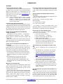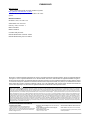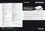
1
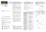
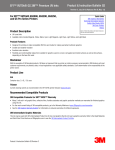
EVBUM2306/D
MatrixCamt
Video Development Kit
User's Guide
Overview
MatrixCam Video Development Kit is a low power, smart 1080p
video streaming device over Wi-Fi® and Ethernet, targeting the
Internet of Things (IoT) market with an open architecture.
To make it an intelligent streaming device, PIR sensor is integrated
to detect movement and to wake up the system to start video
streaming. The system has the additional option for wake up through
Bluetooth® Low Energy (BLE). On wake up, a push notification is
sent to a mobile device alerting the user to view live stream or still
image indicating activity. The product will have different resolution
selection options for video streaming. The product supports
microSDt card slot and cloud service option for storage and playback
of images/video clips. The camera connects to a cloud service with
support for both video on demand (VOD) and live streaming.
Additionally, user will be able to configure the IoT device using
a GUI or mobile application. To receive the requests from this GUI,
an embedded HTTP server is provided in the IoT device.
The following features will be controlled by the GUI:
• Network Configuration
• Video Configuration
• View Live Stream
• Cloud Storage
• microSD Card Recording and File List
• Firmware Upgrade
www.onsemi.com
EVAL BOARD USER’S MANUAL
Figure 1. MatrixCam VDK
Features
• 1/2.7-Inch 2.1 Mp/Full HD Digital Image Sensor: ON Semiconductor
AR023Z
• High-Performance Digital Media System-on-Chip (DM SoC)
•
•
•
•
•
•
•
•
•
Processor: TI DaVinciDM368 SoC
Battery Power Supply Option: ON Semiconductor NCP1855 Battery
Charge Controller + LC709202F Industry State of Art Fuel Gauge
Supported Resolutions: 1920 × 1080, 1280 × 720, 640 × 360,
320 × 180
Supported Bitrates: 64 Kbps, 128 Kbps, 192 Kbps, 256 Kbps,
512 Kbps, 1 Mbps, 2 Mbps, 3 Mbps, 4 Mbps, 5 Mbps
Supported Frame Rates: 5, 10, 15, 20, 25, 30
Two Wake-Up Options: BLE (Bluetooth Application), PIR Motion
Detection
Record Images to microSD Card
Record Video Clips to microSD Card and Cloud
Firmware Upgrade through Web-GUI and microSD Card
File Recording in .AVI Format; Supporting Image Snapshot
© Semiconductor Components Industries, LLC, 2015
September, 2015 − Rev. 1
1
• Live Stream to Androidt and iOS®
• Support 2-Way Audio
• Support Wireless Network
•
•
(Wi-Fi/802.11/b/g) Mobile
Multi-Level Users Management and
Passwords Definition
Support Multiple Network Protocols:
HTTP/TCP/IP/DDNS/SNTP/DHCP/FTP
Package Content
The MatrixCamt VDK contains the
following list of items:
• Camera (1 pc)
• LAN Cable (1 pc)
• Micro-USB Cable (1 pc)
• 8 GB microSD Card & Adapter (1 pc)
Publication Order Number:
EVBUM2306/D
EVBUM2306/D
PC Hardware Requirements
Product Views
Minimum PC hardware requirements for proper
functionality of the MatrixCam VDK:
• CPU: 2.06 GHz or Above
• DDRAM Memory: 256 MB or Above
• Network Card: 10 MBit/s
• Video Card: 64 MB or Above Memory
• Wi-Fi Adapter
Explanatory notes to Figure 2a−d:
1. Mic Input
2. LEDs Indicator (see Table 1 for More Details)
3. Lens + AR023Z Digital Image Sensor
4. PIR Sensor
5. Li-Ion Battery Inserted in the MatrixCam VDK
Base Compartment
6. Micro-USB Interface to Power the MatrixCam
VDK from a PC
7. Ethernet RJ45 10/100 Mbps LAN Port
8. Reset Button
9. Power Button
10. Rotary Arm to Change Tilt of the Camera
11. Speaker
12. Micro-USB Interface for Debugging via Terminal
Emulator Program
13. microSD Card Slot
PC Operational Systems and Web-Browsers
Supported
• Windows® System (7, 8, 10):
Mozilla Firefox®: Version 36 and Above Supported
(Recommended)
♦ Internet Explorer® (IE): Version 8 and Above
Supported, Recommended Versions: IE 10/11/12
MacOs® System (10.10.x):
♦ Safari®: Version 8.x and Above Supported
Linux® System (Ubuntu 12.04):
♦ Mozilla Firefox: Version 36 and Above Supported
♦
•
•
7
1
2
6
LED1
LED2
LED3
8
9
10
3
11
4
5
5
a. Front View
b. Rear View
11
2
12
9
c. Left-Side View
d. Right-Side View
Figure 2. Product Views
www.onsemi.com
2
EVBUM2306/D
Hardware Instructions
3. Optionally, you can plug-in another micro-USB
cable into the camera (Left-side view, slot 12) and
then into USB slot in your PC for debugging via
terminal emulator program.
4. Optionally, you can insert a microSD card
(Right-side view, slot 13) into the particular slot to
be able to record/store video images and
snapshots.
Follow the steps below to set up your MatrixCam VDK
hardware to ensure proper operation:
1. Plug in the micro-USB cable into the camera (Rear
view, slot 6) and then into USB slot in your PC to
power the MatrixCam VDK.
2. Plug in the LAN network cable into the camera
and then into your PC Ethernet RJ45 slot.
Table 1. LED SCHEME
State
Charging
Full Charge/Charge Connected
Device/Usage Error
LED3
LED2
OFF
FLASHING
Device(DM368) ON
ON
Device(DM368) OFF
OFF
Device Booting (DM368 Turning ON)
ON/OFF Button Pressed (For Turning ON)
LED1
ON
FLASHING
FLASHING
FLASHING
Any Recording
ON
Wi-Fi Error/Not Connected
FLASHING
1. Following cases will trigger Device/Usage Error situation: microSD card storage issue; Wired network issue; Multiple-boot failure and
reaches secondary firmware; Low battery indication.
Software Instructions
MatrixCam VDK Start Up
For video streaming, the MatrixCam VDK GUI requires
the VLC multimedia player to be installed:
• Windows System: Install the VLC 32-bit version
(http://www.videolan.org, freeware). Please ensure the
web plug-in Active X is selected during the installation.
When particular browser is opened, a pop-box appears
on screen asking for permission to run the plug-in.
Allow (Enable) the plug-in for enabling the MatrixCam
VDK live streaming.
• MacOs System: Download the mentioned browser
plug-in to embed the VLC player (download the VLC
web plug-in from
http://www.videolan.org/vlc/download−macosx.html).
• Linux System: Execute command ‘sudo apt-get install
browser-plugin-vlc’ in terminal of LINUX system. Go
to the MatrixCam VDK GUI (see the steps below in
next section) and enable the VLC web plug-in.
Push and hold the power button for a few seconds to power
it up. LED2 and LED3 flash at this time.
• PIR Interrupt: Making a movement in front of camera
will trigger the PIR sensor and wake up the MatrixCam
VDK (LED2 starts blinking). As soon as motion is
detected, recording will start if a microSD card (Class 6
or above) is inserted.
Note: It is not possible to trigger the PIR sensor till 2 minutes
initialization period after power up.
• BLE Interrupt: First download the BLE application
depending on used Bluetooth supported mobile device:
♦ Android mobile device (Motorola Nexus 5, 6 or 7 is
recommended): nRF Master Control Application
(http://play.google.com/store/apps/details?id=no.nor
dicsemi.android.mcp&hl=en)
♦ iOS iPhone®: nRF UART Application
(http://itunes.apple.com/us/app/nrf−uart/id61459490
3?mt=8)
♦ iOS iPad®: Adafruit Bluefruit LE Connect
Application
Note: We recommend installing terminal emulator program
for debugging the DaVinciDM368 communication via
serial port (terminal emulator program emulates serial port):
• Windows System: Download and install the Tera Term
software (free of charge).
• Linux System: Install minicom serial communication
program (see APPENDIX installation steps).
• MacOs System: Refer to the following link to install on
Mac: http://pbxbook.com/other/mac−tty.html. Same
procedure to be followed as mentioned for Linux
System.
Further, enable the Bluetooth of the mobile device. Open
the BLE application and search for OSMU_ICDK name in
the next step. Connect to MatrixCam VDK. The BLE trigger
will happen and this will wake up the board (LED2 starts
blinking). Recording for the specified time interval (by
default 2 minutes) will start while assuming a microSD card
(Class 6 or above) is inserted.
• You can now access the MatrixCam VDK GUI
(see the next section).
www.onsemi.com
3
EVBUM2306/D
Figure 3. LAN Network Adapter Settings (Windows)
GUI Interface Initiation
To access the GUI interface, first set up your local PC
LAN network adapter.
Windows System (Figure 3):
1. Go to Network and Sharing Center (Control
Panel −> Network and Internet −> Network and
Sharing Center).
2. Go to Change Adapter Settings and change your
local LAN network adapter settings:
IP address: 192.168.1.xxx (xxx = from 1 to 253,
make sure xxx p 168 since 192.168.1.168 is the
MatrixCam VDK default static IP address)
Subnet mask: 255.255.255.0 (default subnet mask
of the MatrixCam VDK)
Default gateway: 192.168.1.1
DNS server:
3. Push the power button to power on the camera.
LED3 and LED2 flash.
4. Use either the BLE or the PIR interrupt to wake up
the camera (see the section above).
5. Open up supported web-browser and enter the IP
address of the MatrixCam VDK: 192.168.1.168.
The GUI log-in page will pop up (Figure 4).
Figure 4. Log-In Page
MacOs System:
1. Open Network Settings to set up network settings
(Figure 5). Go to System Preferences −> Network
Settings.
2. Repeat the steps 2, 3, 4, 5 above to access the GUI
log-in page.
Figure 5. LAN Network Adapter Settings (MacOS)
www.onsemi.com
4
EVBUM2306/D
Linux System:
1. Open Network Connections to set up network
settings (Figure 6). Go to
System −> Preferences −> Network Connections.
2. Repeat the steps 2, 3, 4, 5 above to access the GUI
log-in page.
Administrator Login
Enter your account and password on the log-in page as
shown in Figure 4. By default, administrator’s username is:
admin and password is: admin. Click “Log in” to enter the
“Live view” screen (Figure 7). To change password, press
“Reset Password” icon located at the top right hand corner
of the page (Figure 7). Confirm the new password by
pressing “Apply” tab in the “Reset Password” page.
Changing the default administrator password is strongly
recommended at the first login.
Figure 6. LAN Network Adapter Settings (Linux)
Figure 7. Live View in the GUI
www.onsemi.com
5
EVBUM2306/D
Figure 8. The List of Users with Their Privileges
Figure 9. System Page
Visitor/Standard User Login
System Settings
The MatrixCam VDK allows up to 9 user accounts to be
created besides the admin account. Only admin can change
the user account settings, including username/password
configuration and privileges. The “Users” page in the
“Configuration” menu displays the list of users (if created)
with their privileges (Figure 8).
The basic system information is available in the “System”
page. User can set time and date either manually or
synchronize with a PC within the same page (Figure 9).
Press “Apply” tab to confirm any change.
www.onsemi.com
6
EVBUM2306/D
Network Settings − Static IP Address
Network Settings − Steps to Enable Wi-Fi Streaming
through GUI
The MatrixCam VDK static IP address is 192.168.1.168
by default. Follow the steps in section “GUI Interface
Initiation” described above to access the GUI using static IP
settings. Default static IP settings can be found in Figure 10.
Follow the procedure below to enable Wi-Fi streaming
through GUI:
1. Access the GUI interface.
2. Go to “Configuration” menu.
3. Press “Network” tab.
4. Go to “WiFi” tab and enable Wi-Fi.
5. Click on “Search” button.
6. Click on desired ESSID to be connected or
optionally enter the ESSID in the text field.
7. Select the Network Security type as: NONE, WEP
or WPA
8. Enter the desired AP/router password (“Key”).
9. Set the “IP Mode” preferably to “DHCP” mode to
get DHCP Wi-Fi IP address (static Wi-Fi
IP address option is also available).
10. Click on “Apply/Save” tab and click on “OK” to
confirm the action.
11. Wait at least 30 seconds. You will get the Wi-Fi IP
address in the field provided at the webpage. You
will see “Status” field change from “Not
Connected” to “Connected”.
12. Use the Wi-Fi IP address to see the GUI interface.
13. Wi-Fi streaming is enabled (you can now unplug
the MatrixCam VDK LAN network cable).
Network Settings − Steps to Enable DHCP
Follow the procedure below to enable Dynamic Host
Configuration Protocol (DHCP) for automatic assignment
of the MatrixCam VDK IP address:
1. Start up the MatrixCam VDK and access the GUI
using static IP address.
2. Log in (Username: admin; Password: admin)
3. Go to “Configuration” menu.
4. Press “Network” tab and enable DHCP
(Figure 10).
5. Click on “Apply/Save” tab and click on “OK” to
confirm the action.
6. The MatrixCam VDK will reboot and get DHCP
IP address.
7. Open the GUI using the DHCP IP address.
NOTE:
It is assumed a 300 Mbps router (for instance TP-LINK) is
properly configured in DHCP mode (DHCP server) at first.
Connect the MatrixCam VDK with router’s LAN port via
a LAN network cable. Use another LAN network cable for
PC-router LAN connection to check the MatrixCam VDK
DHCP IP address (you can optionally check the
MatrixCam VDK DHCP IP either via router’s interface or
via Windows Explorer in your PC). You can also check the
MatrixCam VDK DHCP IP by connecting USB debug
cable. Open respective terminal based on your OS and
type Login as “root”. Type “ifconfig” on terminal and check
IP address of eth0. This is the new DHCP IP address
assigned to the MatrixCam VDK by router.
NOTE:
It is assumed your local wireless network is properly
configured using a 300 Mbps router (for instance TP-LINK)
when attempting Wi-Fi streaming through GUI.
Figure 10. Network Page − Static IP Settings
www.onsemi.com
7
EVBUM2306/D
Network Settings − Steps for WAN Streaming
through GUI
8. Get the Public IP WAN address for the router
(establish WAN network connection before).
9. Now user can access the board/live video from
anywhere using that router Public IP WAN
address, followed by RTSP port (RTSP port
default is 8551).
Follow the steps below to access the GUI interface
remotely (WAN):
1. Access the GUI interface.
2. Go to “Configuration” menu.
3. Press “Network” tab.
4. Select “DHCP/Static IP Settings” depending upon
your router configuration.
5. Go to “Port Settings” tab and enable the check box
for “UPnP Port Forwarding” (WAN), Figure 11.
6. Click on “Apply/Save” tab and “OK” to confirm
the action.
7. Go to your router configuration page.
Example: Let us consider user’s router Public IP WAN
address is 180.59.64.34. Client can then access the
MatrixCam VDK by typing 180.59.64.34:8551 to
web-browser (it is assumed client’s device is connected to
the same WAN network).
NOTE:
It is assumed your LAN and WAN network is properly
configured using a 300 Mbps router (for instance TP-LINK)
when attempting WAN streaming through GUI.
Figure 11. Network Page − Port Settings
Using an Android Device to Connect to
the MatrixCam VDK
Receiving Push Notifications
Please refer to the Cloud Integration Guide, “Cloud Push
Notification” section for more details (AND9264/D).
An Android device can be used to interact with the
MatrixCam VDK for the following functions:
Waking Up the MatrixCam VDK using Bluetooth Low
Energy (BLE)
a. Install the Nordic BLE App from the Google
PlayStore.
b. Wake up the MatrixCam VDK (see “MatrixCam
VDK Start-up” section for more details)
Viewing the Live Stream
a. Install the VLC multimedia player to your Android
based mobile device from Google® PlayStore
(http://play.google.com/store/apps/details?id=org.
videolan.vlc&hl=en).
b. Connect Android based mobile device to Wi-Fi
ESSID of the same router connected to the
MatrixCam VDK.
c. Start up the VLC multimedia player and choose
“Open Network Stream” under “Media”
bookmark.
d. If both the MatrixCam VDK and Android Device
are on the same LAN: Enter the MatrixCam VDK
IP address to see the live streaming from the
MatrixCam VDK.
e. If the MatrixCam VDK has to be accessed from
the WAN: Enter the router WAN IP address
followed by RTSP port number (8551) in
“Network” section to see the live streaming from
the MatrixCam VDK.
NOTE:
Recommended Android Devices are: Nexus 5/6/7.
Using an iOS Device to Connect to the MatrixCam VDK
An iOS Device can be used to interact with the MatrixCam
VDK for the following functions:
Viewing the Live Stream
a. Connect iOS based mobile device to Wi-Fi ESSID
of the same router connected to the MatrixCam
VDK.
b. Install the VLC multimedia player app from the
AppStore (http://itunes.apple.com/us/app/vlc−
for−ios/id650377962?mt=8).
c. Start up the VLC multimedia player and choose
“Open Network Stream” under “Media” bookmark.
www.onsemi.com
8
EVBUM2306/D
Steps to Enable Audio & Audio Settings
d. If both the MatrixCam VDK and Android Device
are on the same LAN: Enter the MatrixCam VDK
IP address to see the live streaming from the
MatrixCam VDK.
e. If the MatrixCam VDK has to be accessed from
the WAN: Enter the router WAN IP address
followed by RTSP port number (8551) in
“Network” bookmark to see the live streaming
from the MatrixCam VDK.
Follow the steps below to enable audio (internal
microphone) on the MatrixCam VDK:
1. Access the GUI interface.
2. Go to “Configuration” menu.
3. Press “Audio” tab (Figure 12).
4. Click to enable audio and configure encoding
technique used, sample rate, bit rate and
input/output volume.
5. Click on “Apply” tab and click on “OK” to
confirm the action.
6. Go back to “Live View” screen – audio should be
now ON (verify the internal MIC functionality).
Waking Up the MatrixCam VDK using Bluetooth Low
Energy (BLE)
a. Install the Nordic BLE App from the AppStore.
b. Wake up the MatrixCam VDK (see “MatrixCam
VDK Start-up” section)
Figure 12. Audio Configuration Settings
Figure 13. Talkback Feature
www.onsemi.com
9
EVBUM2306/D
• Video Mode: High-Dynamic-Range (HDR) mode,
Two-Way Audio (“Talkback”)
The MatrixCam VDK features a “talkback” function, i.e.
two-way audio streaming is possible. The talkback feature
can work only under Windows System using Internet
Explorer web-browser for now and other web-browsers will
be supported in the future. Follow the steps below to enable
talkback function:
1. Access the GUI interface.
2. Click on the Talkback button present on top of the
GUI “Live View” screen and wait for the Talkback
button to turn green (Figure 13). Now two-way
audio is enabled and you can utilize the feature.
•
•
•
•
•
Linear mode
Compression Format: H.264 default
Resolution: 180p, 360p, 720p, 1080p
Frames per Second (fps): 5, 10, 15, 20, 25, 30
Rate Control: Variable Bit Rate (VBR), Constant Bit
Rate (CBR)
Bit Rate: 64 KBps, 128 KBps, 256 KBps, 512 KBps,
1 MBps, 2 MBps, 3 MBps, 4 MBps, 5 MBps
Video Encoding and Video Parameters
NOTES: 1. Click on “Apply/Save” tab and click on “OK” to confirm
any change, otherwise changes do not take effect.
2. HDR mode is currently not available and will be included
in future release.
Video encoding is a process of codifying the bits of data
that make up a digital video recording into format
compatible with most common types of web-players (VLC
player) and mobile devices. User can set following video
encoding controls (Figure 14):
In addition, user can adjust/tune video stream appearance
as needed under “Video Parameters” tab (Figure 15). User
has to click on “Apply” tab and click on “OK” to confirm any
change. User can restore the settings to default video
parameters by pressing “Default” button.
Figure 14. Video Encoding Controls
www.onsemi.com
10
EVBUM2306/D
Figure 15. Video Parameters Controls
Taking Snapshots onto a microSD Card
The GUI interface allows to take snapshots and
consequently to save them onto a microSD card (Class 6 or
above). Follow the steps below to take snapshots:
1. Access the GUI interface and go to “Maintenance”
menu.
2. Press “SD Card” tab to start maintenance of your
microSD card (Figure 16).
3. Press “Remove” tab to unmount microSD card.
NOTE:
4. Insert microSD card (Class 6 or above) into
microSD card slot.
5. Press “Mount” tab to mount microSD card.
6. Go to “Recording” menu and check microSD card
status information. You should see valid size
information and microSD card’s status to be
connected (Figure 17).
7. Click on “Take Snap” tab to take a snapshot.
8. Click on “File List” tab and see snapshot (list of
snapshots) saved in JPG format (Figure 18).
User can optionally unmount microSD card in the GUI
before insertion into microSD card slot.
Figure 16. microSD Card Maintenance
www.onsemi.com
11
EVBUM2306/D
Figure 17. microSD Card Status and File List
Video Recording onto a microSD Card
6. Go to “Recording” menu and check microSD card
status information. You should see valid size
information and microSD card’s status to be
connected (Figure 17).
7. Go to “Recording Settings” and set total video
recording time (“Recording Duration” in the GUI)
as well as video partition time (i.e. number of
video files, “Chunk Duration” in the GUI).
8. Save the settings − clicking on “Save” button.
9. Now click “Record” to start recording. Click on
“File List” tab back in “Media Storage” screen and
see video files saved in AVI format (Figure 18).
Follow the steps below to record video onto a microSD
card:
1. Access the GUI interface and go to “Maintenance”
menu.
2. Press “SD Card” tab to start maintenance of your
microSD card (Figure 16).
3. Press “Remove” tab to unmount microSD card.
NOTE:
User can optionally unmount microSD card in the GUI
before insertion into microSD card slot.)
4. Insert microSD card (Class 6 or above) into
microSD card slot.
5. Press “Mount” tab to mount microSD card.
Figure 18. File List of microSD Card
www.onsemi.com
12
EVBUM2306/D
Push Notification
Cloud Configuration
This feature allows user to forward text notifications
(messages) to an Android/iOS based mobile device
(Figure 19). Follow the steps below to utilize push
notification:
1. Enable the push notification feature at first.
2. Enter the push server URL (your Cloud Messenger
Server).
3. Enter any text message to the “Message” box.
4. Press “Send the Message” and you should get the
message on your mobile device.
The “Cloud Configuration” tab allows user configuring
the cloud credentials (Figure 20). For more information
please refer to the MatrixCam Video Development Kit
Cloud Integration Guide (AND9264/D).
Figure 19. Push Notification
Figure 20. Cloud Configuration
www.onsemi.com
13
EVBUM2306/D
Maintenance − Configuration
• “Restore” button: Click this button to restore all the
There are five configuration options available under
“Config” screen in “Maintenance” (Figure 21):
• “Save” button: Click this button to save the current
configuration setting.
• “Download” button: Click this button to download the
current configuration setting in CFG format into default
location.
settings to the factory default values.
• “Upload” button: Click this button to upload any saved
•
configuration file.
“Delete” button: Click this button to delete the present
configuration setting.
Figure 21. Configuration Options
Maintenance – Reboot
The MatrixCam VDK runs in disabled stand-by mode by
default after start-up, i.e the MatrixCam VDK does not go
to sleep mode and streams continuously. Optionally, user
can enable the stand-by mode and then the MatrixCam VDK
will go into a low power stand-by mode after 2 minutes of
being idle itself (Figure 22).
The MatrixCam VDK software reboot is available in case
of its abnormal operation. User can choose the particular
configuration setting and perform the MatrixCam VDK
restart with the selected configuration (Figure 22).
Figure 22. Software Reboot and Stand-By Mode Feature of the MatrixCam VDK
Maintenance – microSD Card
Maintenance – Firmware Upgrade using the GUI
As mentioned in the video recording section above,
microSD card maintenance (remove/mount/format) is
available under the “SD Card” tab (Figure 16).
An existing MatrixCam VDK firmware can be upgraded
via the GUI interface under “Firmware” tab (Figure 23−25).
It consists of system firmware and GainSpan Wi-Fi module
firmware.
www.onsemi.com
14
EVBUM2306/D
Figure 23. MatrixCam VDK Firmware Upgrade (1 of 3)
Figure 24. MatrixCam VDK Firmware Upgrade (2 of 3)
8. Another screen will get opened indicating success
of the procedure.
9. Now click on “Reboot” button.
10. Wait for 40 seconds and let the system be
upgraded to the new file system after reboot.
11. System firmware upgrade is finished and the GUI
with the new file system will automatically get
opened.
Follow the steps below to upgrade system firmware:
1. Access the GUI interface and go to “Maintenance”
menu.
2. Press the “Upgrade” button under “Firmware” tab
and click on “OK” when prompted.
3. Wait for 45 seconds as system prepares itself for
firmware upgrade.
4. A webpage will be opened automatically after
45 seconds and user will be able to see the option
to do Filesystem and Kernel Upgrade and upload
the new system file.
5. Browse the new file system image named
“MATRIXCAM_FS” and upload it.
(Only this file system name is allowed)
You can also update kernel image:
Browse the new kernel image named
“uImage_icdk_dm365” and upload it.
(Only this kernel name is allowed)
6. Click on “Upgrade” button.
7. Now wait until the whole process is completed.
Figure 25. MatrixCam VDK Firmware Upgrade (3 of 3)
www.onsemi.com
15
EVBUM2306/D
7. Now wait until the whole process is completed.
Another screen will get opened indicating success
of the procedure.
8. Wait for 60 seconds and let the system be
upgraded to the new file system after reboot.
9. GainSpan Firmware upgrade finished and the
System booted with new GainSpan Firmware
Image.
Follow the steps to upgrade GainSpan Wi-Fi module
firmware:
1. Access the GUI interface and go to “Maintenance”
menu.
2. Press the “Upgrade” button under “Firmware” tab
and click on “OK” when prompted.
3. Wait for 45 seconds as system prepares itself for
firmware upgrade.
4. A webpage will be opened automatically after
45 seconds and user will be able to see the option
to do GainSpan Upgrade and upload the new
GainSpan image.
5. Click on “Browse” button and choose the image
file named gs2000_SingleImage.bin with which
you want to upgrade the GainSpan Wi-Fi module.
(Only this image file name is allowed)
6. Click on “Upgrade” button.
Maintenance – Log List
The log list available under “Log” tab keeps records
created either as system or event logs (Figure 26). It
provides with brief description and date/time information of
all logs. User can search for any particular log of interest,
download the list of logs to PC or delete the current list of
logs if needed.
Figure 26. List of Logs
Maintenance – SSL Certificate
6. After successful upload, a success message will
appear on screen.
7. Reboot the MatrixCam VDK and then access the
GUI interface.
8. Now the GUI will come with the new uploaded
custom SSL certificate.
Follow the steps below to upload custom SSL certificate
and SSL key:
1. Access the GUI interface and go to
“Maintenance” −> ”SSL”.
2. Click on “Certificate” button and then upload the
new custom certificate named ssl_cus_cert.pem.
(Only this name will be accepted for certificate)
3. After successful upload, a success message will
appear on screen.
4. Access again the GUI interface and go to
“Maintenance” −> ”SSL”.
5. Click on “Key” button and then upload the new
custom key named ssl_cus_key.pem.
(Only this name will be accepted for certificate)
Maintenance − Battery Status
The MatrixCam VDK alternative power supply option via
4200 mAh Li-Ion battery is available. For this purpose,
the NCP1855 battery charge controller and the LC709202F
fuel gauge IC are integrated to assure proper battery
operation and long-term functionality. The current battery
status can be checked under “Battery” tab (Figure 27).
www.onsemi.com
16
EVBUM2306/D
Figure 27. Battery Status
Maintenance − Wi-Fi Calibration
There is a provision of improving Wi-Fi performance and
connectivity. Re-calibration might be needed if the
MatrixCam VDK repeatedly fails to connect to AP over
Wi-Fi or there seems to be performance issues in streaming
over Wi-Fi. This happens because of change of RF
environment (temperature/channel congestion, etc.) and
there is mismatch with calibration data of the Wi-Fi module.
To re-calibrate livecal data of the module, one needs to press
the “Initiate Calibration“ button and power cycle the device
(Figure 28).
Figure 28. Wi-Fi Calibration
Cloud Integration
API
MatrixCam VDK is integrated with multiple cloud
services Out-of-the-Box. Please refer to the MatrixCam
Video Development Kit Cloud Integration Guide
(AND9264/D).
MatrixCam VDK comes with a rich set of APIs to create
custom apps on Android, iOS and HTML5. This is described
in the MatrixCam Video Development Kit Software
Developer’s Guide (AND9263/D).
www.onsemi.com
17
EVBUM2306/D
APPENDIX
Frequently Asked Questions (FAQs)
No Changes Visible after Changing Settings in the GUI
This chapter answers the most common FAQs and should
be of help in case you experience some issues when using the
MatrixCam VDK product. For troubleshooting tips and
additional questions that are not covered within the user
guide please refer to our web-page: www.onsemi.com or
contact technical support.
Any change in the GUI setting has to be confirmed by
“Apply” button, otherwise changing of setting does not take
effect.
NOTE:
System Unstable when Multiple RTSP Clients are
Connected
The maximum number of RTSP clients supported by the
MatrixCam VDK is listed below:
LAN Streaming: 4 × 1080p @ 30 fps @ 2 Mbps
Wi-Fi Streaming:
• 1 × 1080p 30 fps @ 2 Mbps
• 2 × 720p 30 fps @ 1 Mbps
At first, we recommend checking the software & hardware
instructions mentioned above in case of abnormal
operation or malfunction of the MatrixCam VDK.
The network connection configuration is important for the
product to operate properly.
Forgot the Admin Username/Password
To reset the administrator username and password, press
and hold down the hardware reset switch located on the back
of MatrixCam VDK for 5 seconds. Release the switch and
the username and password will reset back to the factory
default administrator username and password.
It is possible to connect more RTSP clients to the
MatrixCam VDK at lower bit rates and/or lower resolutions
mentioned above, depending on network bandwidth.
How Do I Use the “Secure RTSP” Option?
Please follow the steps below to enable “Secure RTPS”
option in the web GUI interface:
1. Access the web GUI interface.
2. Go to “Configuration” −> “Network”.
3. Click on Network Tab in the Side Menu.
4. Enable “Secure RTSP” option.
5. Secure RTSP is now enabled and now whenever
user will try to run the live streaming via VLC
web plug-in using the RTSP URL, he or she will
be asked for their username and password.
Unable to Access the MatrixCam VDK Web GUI
on My Local Network
(On Windows) Go to: My Computer −> Control Panel −>
Network & Dial-Up Connections −> LAN −> Attributes −>
Internet Protocols (TCP/IP), and check IP Address and
Subnet Mask.
Make sure the MatrixCam VDK IP address shares the
same subnet mask as your work station when configuring the
MatrixCam VDK IP manually.
Unable to Access the MatrixCam VDK Web GUI via
the Internet
The VLC Web Plugin will Not Work with Safari on My
Mac
Assuming that the ActiveX is and the VLC player is
installed correctly (see “No Video Stream” section below),
there might be few possible reasons explaining why one
cannot access the MatrixCam VDK GUI via internet:
• The MatrixCam VDK HTTP port (default HTTP port:
80) is blocked by firewall or anti-virus software. Please
change the HTTP port (for instance to 8080) and try
again.
• Port mapping does not work: Enter the router’s
interface to which the MatrixCam VDK CD is
connected and enable router’s UPNP function. Enter
the GUI and make sure “UPnP Port Forwarding” option
is enabled.
The steps for installing the VLC web plug-in are as
follows:
1. Download the VLC web plug-in (VLC for OS X
web plug-in 2.2.132 & 64 bit Universal Binary
package) using the link as provided below:
http://www.videolan.org/vlc/download−macosx.
html
2. Once it gets downloaded, double-click on the
Downloaded File to install the contents and the
folder should be opened automatically.
3. Copy the VLC plugin file into the Internet Plugins
Folder which can be seen in the installed folder.
4. Restart the Safari web-browser or Mac computer
to complete the installation and then run the server
IP. You should now be able to see the MatrixCam
VDK’s live stream.
Web GUI isn’t Streaming Video
Make sure the 32-bit VLC multimedia player and ActiveX
plugin are both installed onto your PC. If either of these
software packages is not installed then you won’t see the
streaming video in the GUI.
If your video stream is grayed out with a symbol in the
middle of the box and you have already installed both the
ActiveX and VLC plugins, then your browser most likely
doesn’t support these plugins anymore. Please use
a web-browser that supports the VLC plugin (e.g. Firefox,
Internet Explorer, or Safari).
Live Video Stream is Corrupted in Internet Explorer on
Windows
User may experience the video live stream malfunction
(image is black and white and corrupted) when running the
GUI interface under IE web-browser. This can happen when
the IE’s window’ zoom ratio is not 100% but rather
a non-standard/custom ratio zoom (for instance 110%).
www.onsemi.com
18
EVBUM2306/D
Live Video Stream Cuts Out for 2−3 Seconds
case you do not use/have a router, follow the steps below to
restore “IP Settings” back to static IP address:
1. Install terminal program for particular operational
system (see the section below for more details).
2. Type “root” to the command line
(DM368_IPNC login: root).
3. Then type “rm –rf /mnt/nand/config/”
to the command line
(root@DM368_IPNC: rm –rf /mnt/nand/config/).
4. This command deletes DHCP setting in the GUI
interface. You should now be able to access the
MatrixCam VDK via static IP address.
When the live video stream is started (the web GUI is
launched), either in a particular web-browser or VLC
streamer, the live stream might cut out for 2−3 seconds and
then come back on again. This is a known issue due to an
internal buffering problem in the VLC web plug in.
All of the Correct Cables are Connected. Why isn’t the
MatrixCam VDK Appearing Over LAN/Wi-Fi?
The MatrixCam VDK is most likely not woken up yet.
Using the “nRF Toolbox” app via Bluetooth or waving your
hand in front of PIR sensor will “wake” the device up. Allow
around 30 seconds for the MatrixCam VDK to show up in
your internet connection list.
Example 2: The System Firmware Corruption and How to
Restore the GUI Interface
Let us consider this particular case. User follows the
system firmware upgrade steps (see the particular section
above for more details), however, for some reasons the file
system image is either damaged or named inappropriately.
The result is the system firmware corruption that makes the
GUI interface no more accessible. To resolve this issue, one
has to boot the system firmware from microSD card which
is included with the MatrixCam VDK package release. This
is a part of the release package available with your product.
Follow the instructions in <MatrixCam_Base Folder>/
System Upgrade/sdutils/sd_boot_readme.txt
In the Recording Section, Will the Video Stop
Recording after the Recording Duration?
How Do I Set Up the Camera to Record Indefinitely
while Overwriting Previous Data?
In “Configuration” −> “Recording” −> “Media Storage”,
you should see a check box in the SD card section labeled
“SD Card file overwrite on card full”. With this box enabled
you should be able to leave the camera recording
indefinitely while past videos/pictures are overwritten by
newer videos/pictures.
When the MatrixCam VDK Wakes Up because of
a Motion Trigger via the PIR Sensor Sometimes Videos
are Not Recorded to the microSD Card
Steps to Install Terminal Emulator Program
If a serial port communication terminal is connected to the
debug micro-USB port of the MatrixCam VDK, there is
known hardware bug with the DM368 that cannot mount the
microSD card correctly during reboot. This causes no videos
to be recorded. The solution is to disconnect the terminal
from the MatrixCam VDK while a motion trigger wakeup is
in progress.
Windows System:
1. Install Teraterm Software (freeware) from internet
(for instance: http://logmett.com/index.php?/
download/tera−term−487−freeware.html).
2. Connect the Console USB Cable.
3. Click on Setup in Menu bar.
4. Select the USB Console COM port (usually
COM15).
5. Select Baudrate as 1152000 under Setup −> Serial
Port. No other changed are needed.
6. Click on OK to confirm the changes.
7. Logs of the DM368 will start to come after the
board is booted up.
Things to Avoid
There are a few improper actions by applying them one
can corrupt the current system firmware and/or GainSpan
Wi-Fi module firmware. In general, “the most sensitive”
items in the GUI interface are network settings (“Network”
tab under “Configuration” menu) and firmware
maintenance (“Maintenance” tab under “Configuration”
menu).
Linux System:
To install minicom to a Linux OS, type “sudo apt−get
install minicom”. Follow the steps below:
1. Type in the terminal “sudo minicom −s”.
2. Select “Serial Port Setup “and Press Enter.
3. Press Shift + A, Enter the Serial Device
“/dev/ttyUSB0”.
4. Press Enter Key.
5. Select “Save setup as dfl”. Press Enter.
6. Select Exit and press Enter key.
7. Reboot the Board.
8. Logs will get to display on the terminal.
Example 1: Lost Connection due to Improper Network
Connection Configuration
Let us consider this particular case. The MatrixCam VDK
IP address is set to static (192.168.1.168) and the
MatrixCam VDK works as expected. If static IP address is
changed to DHCP mode you will lose connection to the
MatrixCam VDK if you confirm this change and the same
time you do have your DHCP server/router configured
correctly. To resolve this issue, you have to properly
configure your router and try again to connect to the
MatrixCam VDK with the assigned DHCP IP address. In
www.onsemi.com
19
EVBUM2306/D
MacOs System:
Refer to the following link to install on MacOs Systems:
http://pbxbook.com/other/mac−tty.html
Follow the same procedure as mentioned above for Linux
System.
Default Parameters
IP address: static, 192.168.1.168
Subnet Mask: 255.255.255.0
Gateway: static, 192.168.1.1
DHCP: Disabled
DDNS: Disabled
Username and password:
Default administrator username: admin
Default administrator password: admin
Bluetooth is a registered trademark of Bluetooth SIG. Firefox is a registered trademark of Mozilla Foundation. Google is a registered trademark
of Google Inc. Linux is a registered trademark of Linus Torvalds. MacOS, iOS, iPhone, iPad and Safari are registered trademarks of Apple Inc.
Windows and Internet Explorer are registered trademark of Microsoft Corporation. Wi-Fi is a registered trademark of the Wi-Fi Alliance. Android
is a trademark of Google Inc. MatrixCam is a trademark of Semiconductor Components Industries, LLC (SCILLC) or its subsidiaries in the United
States and/or other countries. microSD is a trademark of SD-3C, LLC in the United States, other countries or both. All other brand names and
product names appearing in this document are registered trademarks or trademarks of their respective holders.
ON Semiconductor and the
are registered trademarks of Semiconductor Components Industries, LLC (SCILLC) or its subsidiaries in the United States and/or other countries.
SCILLC owns the rights to a number of patents, trademarks, copyrights, trade secrets, and other intellectual property. A listing of SCILLC’s product/patent coverage may be accessed
at www.onsemi.com/site/pdf/Patent−Marking.pdf. SCILLC reserves the right to make changes without further notice to any products herein. SCILLC makes no warranty, representation
or guarantee regarding the suitability of its products for any particular purpose, nor does SCILLC assume any liability arising out of the application or use of any product or circuit, and
specifically disclaims any and all liability, including without limitation special, consequential or incidental damages. “Typical” parameters which may be provided in SCILLC data sheets
and/or specifications can and do vary in different applications and actual performance may vary over time. All operating parameters, including “Typicals” must be validated for each
customer application by customer’s technical experts. SCILLC does not convey any license under its patent rights nor the rights of others. SCILLC products are not designed, intended,
or authorized for use as components in systems intended for surgical implant into the body, or other applications intended to support or sustain life, or for any other application in which
the failure of the SCILLC product could create a situation where personal injury or death may occur. Should Buyer purchase or use SCILLC products for any such unintended or
unauthorized application, Buyer shall indemnify and hold SCILLC and its officers, employees, subsidiaries, affiliates, and distributors harmless against all claims, costs, damages, and
expenses, and reasonable attorney fees arising out of, directly or indirectly, any claim of personal injury or death associated with such unintended or unauthorized use, even if such claim
alleges that SCILLC was negligent regarding the design or manufacture of the part. SCILLC is an Equal Opportunity/Affirmative Action Employer. This literature is subject to all applicable
copyright laws and is not for resale in any manner.
PUBLICATION ORDERING INFORMATION
LITERATURE FULFILLMENT:
Literature Distribution Center for ON Semiconductor
19521 E. 32nd Pkwy, Aurora, Colorado 80011 USA
Phone: 303−675−2175 or 800−344−3860 Toll Free USA/Canada
Fax: 303−675−2176 or 800−344−3867 Toll Free USA/Canada
Email: [email protected]
N. American Technical Support: 800−282−9855 Toll Free
USA/Canada
Europe, Middle East and Africa Technical Support:
Phone: 421 33 790 2910
Japan Customer Focus Center
Phone: 81−3−5817−1050
www.onsemi.com
20
ON Semiconductor Website: www.onsemi.com
Order Literature: http://www.onsemi.com/orderlit
For additional information, please contact your local
Sales Representative
EVBUM2306/D