1
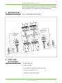
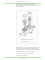
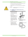
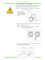
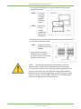
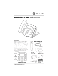
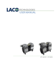
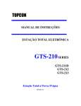
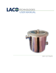
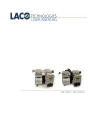
USER MANUAL
UN-200V / UN-200VH
CONTACT US
PHONE/FAX
Toll Free: 800.465.1004
Phone: 801.486.1004
Fax: 801.486.1007
ADDRESS
LACO Technologies, Inc.
3085 West Directors Row
Salt Lake City, UT 84104
WEB
www.lacotech.com
[email protected]
TECHNICAL SUPPORT AND SERVICE
[email protected]
SMT-09-1007 revA1
ii
© 2011 LACO TECHNOLOGIES, INC.
CONTENTS
1.SCOPE..................................................................................... 1
2.INSTALLATION...................................................................... 1
3. BASIC OPERATION............................................................... 1
4.MAINTENANCE..................................................................... 2
5. PARTS AND ACCESSORIES................................................. 2
6.SPECIFICATIONS................................................................... 3
7.TROUBLESHOOTING........................................................... 4
8. PREVENTIVE MAINTENANCE............................................. 4
9. REQUIRED TOOLS AND MATERIALS................................ 5
10. COMPONENT REPAIR......................................................... 6
iii
© 2011 LACO TECHNOLOGIES, INC.
LACO USER MANUAL – UN-200H / UN-200VH
iv
© 2015 LACO TECHNOLOGIES, INC.
LACO USER MANUAL – UN-200V / UN-200VH
1. SCOPE
This manual contains operation and maintenance information for UN-200V
and UN-200VH oil-free piston vacuum pumps. Please identify the model
number when ordering parts.
2. INSTALLATION
2.1
UNPACKING
Inspect the box and pump carefully for any signs of damage incurred in
transit. Save all packaging for freight claims.
2.2
INSTALLATION
Install the pump in a horizontal position on a level surface so that the
pump is evenly supported on its rubber feet. The pump must be installed
in a dry, well ventilated place, which is as free of dust as possible. Leave
12-18 in of space around the pump to allow proper cooling. Also, adequate
ventilation must be provided for the fans, radiator, and motor.
If the pump is not going to be permanently mounted, attach the suction
cup feet into the mounting holes.
Never operate the pump outdoors in the rain or near an open flame.
2.3
ELECTRICAL CONNECTION
Check the voltage and frequency on the identification plate before starting
the electrical power of motor. The standard thermal protector will trip
automatically if the maximum permitted temperature is exceeded.
The pump will restart automatically when it is cooled down.
3. BASIC
OPERATION
Only atmospheric air is permitted as working media. Do not evacuate
corrosive liquid or vapor with the pump.
Excessive dirt will damage the pump so always remember to check the
inlet filter before operating. After the pump has been stopped, air will
gradually seep back into the evacuated spaces. If this is undesirable, it will
be necessary to fit a check valve in front of the inlet port.
The standard pump can not start against a full vacuum.
Improper disassembly or repair will damage the pump. Only qualified
personnel can do repair service.
1
© 2015 LACO TECHNOLOGIES, INC.
LACO USER MANUAL – UN-200H / UN-200VH
The pump does not use pump oil. Do not lubricate any of the parts with oil,
grease, or petroleum products nor clean with acids, caustics, or chlorinated
solvents at any time. This can affect the service life of the pump.
4. MAINTENANCE
5. PARTS AND
ACCESSORIES
Figure 1: UN-200V AND VH Exploded View
1. Repair kit UN-Z-P1
2. Inlet Filter VFR-B
3. Vacuum filter, Gauge and Regulator LMSA 5166
4. Suction Cup Foot LMSA 5165
5. Capacitor Assembly LMSA 106257
2
© 2015 LACO TECHNOLOGIES, INC.
LACO USER MANUAL – UN-200V / UN-200VH
6. SPECIFICATIONS
LACO UN-200 Dry Vacuum Pumps are ideal for any industrial vacuum applications that require vacuum
levels from atmospheric pressure to 10 torr (29inHG). Some applications include vacuum degassing, altitude
simulation, bubble emission leak testing, and product or package testing. In comparison to other dry
membrane pumps such as dry diaphragm pumps, the UN-200 rotary piston design provides much higher flow
rates at a reduced cost. Their economical, compact, lightweight, oil-free design and quiet operation is further
enhanced by the standard vacuum regulator which allows operators to easily control the ultimate vacuum level
with an adjustable screw valve.
FEATURES
• Oil-free design
• Analog 0-30in Hg vacuum gauge
• Manual Vacuum Regulator
• Inlet filter trap
• Low noise level
• Maintenance free operation
• On/off switch on an 120V IEC power box with
6 ft. cord
• Exhaust muffler
UN-200V
• Suction cup and mounting style isolation feet
included
SPECIFICATIONS
MODEL
UN-200V
UN-200VH
Max Air Flow (CFM)
4.4
7.0
Max Vacuum (inHg/Torr)
29.1/10
27.9/45
Voltage (single phase), 60Hz
120
120
Max Amps
3.2
5.9
Motor Capacity (watts
450
680
Inlet
1/4” NPT or 3/8” 1/4” NPT or 3/8”
hose barb
hose barb
Noise Level (dBA at 3 feet)
56
56
UN-200VH
DIMENSIONS (inches)
MODEL
H
D
W
MOUNT HOLE MOUNT HOLE
WIDTH
LENGTH
I
WEIGHT
UN200V
10.5”
8”
14”
3.5”
8”
1/4” NPT
23.1 lbs.
200VH
10.5”
8”
14”
3.7”
8.9”
1/4” NPT
23.1 lbs.
(SPECIFICATIONS SUBJECT TO CHANGE WITHOUT NOTICE)
3
© 2015 LACO TECHNOLOGIES, INC.
LACO USER MANUAL – UN-200H / UN-200VH
7. TROUBLESHOOTING
If you are having a problem with your compressor, use this table to help
determine the cause(s):
Table 1: Troubleshooting
PROBLEMS
Low
Flow
Low
Pressure
Unit Will
Not Start
X
X
X
X
X
X
POSSIBLE CAUSES
Motor
Overheats
CORRECTIVE ACTIONS
Loud
Unit
X
High voltage at compressor Reduce voltage
X
Low voltage at compressor
Increase voltage
X
Damaged valves
Replace flapper valves
X
X
Debris in valves
Remove debris and check
for valve damage
X
X
X
Damaged gaskets
Replace gaskets
X
X
X
Worn Cup
Replace piston cup
X
X
X
Loose head screws
Tighten head screws
Broken fan
Replace fan
Bent motor shaft
Replace entire unit
Damaged capacitor
Replace capacitor
Loose fittings
Tighten fittings
Insufficient ventilation in
enclosure
Increase air circulation to
enclosure
Worn bearings
Replace Eccentric Bearing
assembly
X
X
X
X
X
X
X
X
X
X
8. PREVENTIVE
MAINTENANCE
X
We recommend you perform the following service to minimize
unexpected downtime for your compressor when serving over 5000 hours.
• Replace the Connecting Rod, Eccentric & Bearing Assembly. (#1)
• Replace the flapper valves. (#12)
• Replace the head O-ring Head gasket. (#7)
• Replace the valve plate’s O-rings. (#15)
4
© 2015 LACO TECHNOLOGIES, INC.
LACO USER MANUAL – UN-200V / UN-200VH
9. REQUIRED
TOOLS AND
MATERIALS
To disassemble and reassemble your pump, you need the following tools
and materials:
• N-m. (Newton meter) Torque wrench (for head screws, connecting rod,
flapper valve screw, and pipe plugs).
• RTD500CN driver (for head screws).
• S3 Allen wrench attachment for torque wrench (for eccentric screw).
• Phillips attachment for torque wrench (for flapper valve screw).
• Screwdriver (for retainer screws).
• Soft, clean cloths.
5
© 2015 LACO TECHNOLOGIES, INC.
LACO USER MANUAL – UN-200H / UN-200VH
10. COMPONENT
REPAIR
10.1 SERVICING THE HEAD, VALVE PLATE ASSEMBLY AND
CONNECTING ROD AND BEARING ASSEMBLY
The head would only need to be replaced if it is visibly damaged.
Component Parts Required
You will need:
• Head (if damaged)
• Head gasket
• Valve plate O-ring
• Complete valve plate
assembly or individual
flapper valves.
• Flapper valve screw(s) if
replacing individual flapper
valve(s).
10.2 SERVICING THE HEAD
1. Disconnect the power.
2. Disconnect all airlines and remove compressor from the enclosure.
3. Remove all screws that fasten to the (1) head (2) compressor housing.
4. Carefully separate the head from the compressor body.
5. Carefully separate the valve plate assemblies (4) from the heads.
6. Remove the head gasket O-rings (3) and replace it.
7. Turn the valve plates over and replace the valve plate gasket
O-rings (5).
ATTENTION
If you are replacing the head and gaskets only, see the
assembly instructions on page 13. To replace the Valve
flappers and connecting rod assembly, see page 7 to
12.
6
© 2015 LACO TECHNOLOGIES, INC.
LACO USER MANUAL – UN-200V / UN-200VH
10.3 SERVING THE VALVE ASSEMBLY
NOTE:
We recommend you remove and replace one flapper valve
at a time. This will help to simplify the repair process and
orient the flapper valve correctly in the valve plate.
10.3.1 TOP SIDE FLAPPER VALVE REPLACEMENT
1. If you are replacing a flapper
valve on the top side of the
valve plate (side facing the
head), remove the flapper
valve screw (1), with a Phillips
screwdriver.
Lift off the valve keeper strip (2),
lift off the Strengthen valve (3),
and lift off the flapper valve. (4).
2. Remove any debris from the
valve plate with water-free,
alcohol. (Soaps and detergents
should not be used
due to the potential for corrosion from soap residue.)
3. Place the valve plate on the
compressor housing and
orient it as illustrated. Make
sure the O-ring head gasket
towards the cylinder. Note the
orientation of the valve ports.
4. Orient a new flapper valve
(1) over Port 1. Observe the
location of at the end of the
flapper valve.
5. Place a valve restraint (3) over
the flapper valve.
6. Place a valve keeper strip (4) over
the valve restraint observing
that the Restraint’s Radium is
facing Valve plate and oriented
as shown in the illustration.
7. Line up the screw holes in all of
the valve components and fix
the screw on the valve plate.
7
© 2015 LACO TECHNOLOGIES, INC.
LACO USER MANUAL – UN-200H / UN-200VH
8. Make sure the flapper valve is centered over the port of the valve plate
and that all of the other components line up with the flapper valve.
9. Tighten the flapper valve screw to 1.3 N-m. using a torque wrench with
a Phillips attachment.
CAUTION
Do not over tighten the flapper valve screw or it will shear
off in the valve plate.
10.3.2 BOTTOM SIDE FLAPPER VALVE REPLACEMENT
1. If you are replacing a flapper
valve on the bottom side of
the valve plate (side facing
the compressor housing),
remove the flapper valve
screw (1) with a Phillips
driver, lift off the valve keeper
strip (2).
2. Clean any debris with a soft,
damp cloth. Turn the
compressor head upside
down and place the valve
plate on the compressor
head and orient it as illustrated. Note the position of the valve ports
and the location of the power leads on the compressor housing.
3. Orient a flapper valve (1) over
Port 2. Observe the location of
the notches (2) at the end of
the flapper valve.
4. Place a valve keeper strip
(3) over the flapper valve,
observing that the radius the
valve plate, and oriented as
shown in the illustration.
8
© 2015 LACO TECHNOLOGIES, INC.
LACO USER MANUAL – UN-200V / UN-200VH
5. Line up the screw holes in all of the valve components and fix them
upon the flapper valve screw by screws.
6. Make sure the flapper valve is
centered over the Port and that
the valve keeper strip lines up
with the flapper valve.
CAUTION
Do not over tighten
the flapper valve
screw or it will shear
off in the valve
plate.
7. Tighten the flapper valve
screw to 1.4 N.m. using a
torque wrench with a Phillips
attachment.
ATTENTION
If you are only replacing the valve flappers, see the
assembly instructions beginning on page 7. If you
are replacing the cup and sleeve turn to the Rebuilding
Connecting Rod Assemblies Section found on page 11.
10.4 SERVICING THE CONNECTING ROD ASSEMBLY AND
ECCENTRIC ASSEMBLY
Refer to the Troubleshooting Guide on page 4 to determine whether
a complete connecting rod assembly, component parts, or an eccentric
needs to be serviced.
Component Parts Required
You will need
• Connecting rod assembly (ices) or piston cups and sleeves.
• Valve plate gasket O-ring (s).
• Head gasket O-ring (s) (if defective).
9
© 2015 LACO TECHNOLOGIES, INC.
LACO USER MANUAL – UN-200H / UN-200VH
10.4.1 REMOVING THE CONNECTING ROD ASSEMBLY AND
ECCENTRIC
NOTE: ONLY REMOVE ONE CONNECTING ROD ASSEMBLY AT A
TIME.
1. Carefully remove the fan by
pulling it straight off the motor
shaft. Do not pull the fan blades.
2. Turn the motor shaft to align
the eccentric set screw, the
connecting rod screw
separately and with the hole of
the housing. (See illustration for
location of access hole).
3. Slide the eccentric bearing assembly
straight off the shaft.
4. Slide and rotation the connecting rod,
remove it from the housing.
ATTENTION
Do not damage the piston cup (4) when you remove the
connecting rod assembly from the compressor housing. If
the cup is damaged, you must replace it.
10
© 2015 LACO TECHNOLOGIES, INC.
LACO USER MANUAL – UN-200V / UN-200VH
10.4.2 REBUILDING CONNECTING ROD ASSEMBLY
If you are rebuilding the connecting rod assembly using component parts,
follow this procedure:
When replacing the piston cup (4), be sure to replace the sleeve (1) at the
same time. Place the connecting rod in a fixture before attempting to
remove the retainer screw. Heat will help to dissolve the Loctite® bond.
1. Remove the retainer screw (2) from the cup retainer.
2. Remove the retainer (3) from the connecting rod.
3. Remove the cup (4) and discard.
11
© 2015 LACO TECHNOLOGIES, INC.
LACO USER MANUAL – UN-200H / UN-200VH
4. Place the new piston cup (4) on the connecting rod.
5. Place a piston cup retainer (3) on the cup/connecting making sure the
boss of the retainer is seated in the pilot of the rod.
6. Insert the retainer screw (2) into the connecting rod (5) and tighten to
3.0 N.m.
ATTENTION
To replace the connecting rod and bearing assembly
continue to page 17.
10.5 ASSEMBLY OF THE CONNECTING ROD TO THE
COMPRESSOR
1. Put cylinder sleeve into trough
of housing keeper and make
connecting rod being vertical.
Note connecting rod screw to
face to housing.
2. Replace eccentric into the shaft
and insert bearing into
connecting-rod bearing. Rotate
eccentric to line up setscrew
with access hole in bottom of
housing. Move main shaft, let
shaft flat and eccentric screen
hole vertically. Tighten screw to
4 -4.5 N.m.
3. Rotate shaft with connecting
rod moving up and down.
Connecting rod can move
without any obstacle at this
moment. Then use an Allen key
to tighten connecting rod screw.
12
© 2015 LACO TECHNOLOGIES, INC.
LACO USER MANUAL – UN-200V / UN-200VH
10.5.1 REASSEMBLING THE COMPRESSOR
After the connecting rod assembly and eccentric are correctly assembled,
you can assemble the valve plates and bead to the compressor.
CAUTION
To prevent damage to the compressor, never apply any
sealant or lubrication to the O-rings.
1. Insert the valve plate
gasket O-ring into the
O-ring groove located on
the bottom of the valve
plate.
2. Position the compressor housing as shown in the illustration. Notice
the orientation of the power leads.
NOTE: Make sure that the connecting rod sleeves are seated
against the compressor housing.
3. Observe the orientation of the valve plate assemblies. Place them on
the compressor housing as shown.
13
© 2015 LACO TECHNOLOGIES, INC.
LACO USER MANUAL – UN-200H / UN-200VH
4. Inset two new head gasket O-ring into the groove located on the
bottom of the Head.
NOTE: Ensure the
valve plate
is properly
engaged
to housing
locators.
NOTE: Ensure that
O-Rings
are fully
assembled in
grooves and
not pinched.
5. Place the head on the valve plate Assemblies observing the position of
the air intake and exhaust ports.
NOTE: Make sure the head
gasket O-rings are not
pinched.
6. Insert the head screws and
tighten each screw until it is
snug. Use 4-4.5 N.m. in a drive to
tighten each head screw.
Caution To avoid property damage or personal injury, always try
rotating the fan by HAND, prior to connecting the unit to the power
source. Check for suction at the air inlet port by placing your finger over
the port as you turn the fan. You should feel a slight suction with each
rotation of the fan. If you don’t feel suction, or if you feel or hear a thump
as you turn the fan, DO NOT CONNECT THE UNIT TO A POWER SOURCE;
review the assembly procedure for possible error.
14
© 2015 LACO TECHNOLOGIES, INC.
LACO USER MANUAL – UN-200V / UN-200VH
10.6 SERVICING THE FAN
If one or both have the fans break use the following procedure:
1. Carefully remove
the fan by pulling it
straight off the motor
shaft.
2. Align the flat on the
motor shaft with the
flat on the fan and slide
the fan back onto the
motor shaft, making
sure the fan clip (1)
faces as shown.
15
© 2015 LACO TECHNOLOGIES, INC.