1
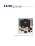
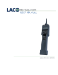
USER MANUAL GASCHECK SF6 CONTACT US PHONE/FAX Toll Free: 800.465.1004 Phone: 801.486.1004 Fax: 801.486.1007 ADDRESS LACO Technologies, Inc. 3085 West Directors Row Salt Lake City, UT 84104 WEB www.lacotech.com [email protected] TECHNICAL SUPPORT AND SERVICE [email protected] SMT-07-1018 A1 ii © 2011 LACO TECHNOLOGIES, INC. CONTENTS 1. SCOPE .................................................................................... 1 2. OVERVIEW ............................................................................ 1 3. SAFETY .................................................................................. 4 4. BASIC OPERATION .............................................................. 4 5. USER SETUP.......................................................................... 6 6. CALIBRATION ....................................................................... 9 7. PARAMETERS ..................................................................... 10 8. DEFAULT SETTINGS .......................................................... 14 iii © 2011 LACO TECHNOLOGIES, INC. LACO USER MANUAL - GASCHECK SF6 1. SCOPE This manual is addressed to those responsible for and using the GasCheck SF6 instrument and applies to software version V1.37BB 2. OVERVIEW 2.1 INTRODUCTION GasCheck SF6 is a portable, mains-independent instrument for leak detection and leak measurement of SF6 gas. Although designed for SF6, other gases with a high affinity for electrons, such as refrigerant R12 may also be detected. Two modes of operation are available, volume loss/time cc/sec (leak detection) and (ppm) concentration of GasCheck in air. All controls and displays required for detection are found in the hand unit. Accurate and clear measurement is achieved from the console touch screen display. Measurements can be stored in the instrument and later transferred to a printer or computer. A battery-powered printer is available. Results may also be downloaded to a computer via the RS2323 link. The only item which needs to be replaced in normal use is the ‘Smart Sensor’ probe. Smart Sensors contain a microchip programmed with specific sensor information. At Switch ON, the console automatically reads sensor information. Smart Sensors are not radioactive and contain nothing harmful. Life is approximately 200 hours. Sensors are changed by switching OFF the instrument and plugging in a replacement. Three (3) are supplied and available as exchange items. The operation of the instrument and sensor require permanent and precise control by software. Any faults give immediate error messages, which are then displayed on the touch screen. This in conjunction with the sample flow monitoring function, ensures the instrument reliably determines and displays all fault conditions. 2.2 CONSOLE CONTROLS Touch-screen for numeric leak rate display and parameter entry. Two red on/off buttons located at the front and right side panel. Both are lit when the instrument is on. White light combines mains supply and battery charge control. This flashes while on charge and is permanently on when the battery is full. A Key allows the transparent front cover to be locked during use. 1 © 2011 LACO TECHNOLOGIES, INC. LACO USER MANUAL - GASCHECK SF6 2.3 HANDGUN DISPLAYS AND CONTROLS The following controls are found on the hand unit: • Analogue gauge displays the response to leaks in %, rather than an absolute value (displayed on the touch-screen), and shows the leak rate in the form of a percentage of the alarm value. This is clearer and easier for an operator. • Handgun Six LEDs indicate status. Table 1: GasCheck SF6 LED Status COLOR NO. DESCRIPTION GREEN 1 READY TO MEASURE. Normal operation. If ON, you may confidently measure. This is OFF whenever the instrument is in standby or programming mode, error condition, or the actual reading is above 20% of the alarm level. RED 2 NOT READY. This light is on whenever the instrument is in the programming mode, or an error condition exists. It flashes during standby mode. GREEN 3 SPECIAL. Desensitize functions, flashes when one of them is active. YELLOW 4 SIGNAL. Switches on whenever a reading above 20% alarm level was taken. Reset by STORE or CLEAR key. RED 5 ALARM. This light is on as long as a reading equal to or above the alarm level is taken. YELLOW 6 MESSAGE. Prompts the operator to read a message that is present on the LCD screen. 2 © 2011 LACO TECHNOLOGIES, INC. LACO USER MANUAL - GASCHECK SF6 2.4 HANDGUN BUTTONS 2.4.1 SQUARE This has two functions: MEASURE MODE and SEARCH (bar graph) MODE. On power-up the SEARCH mode is automatically selected, the touch screen displays a bar graph. This is ideal for fast and ultra low-level leak detection (~10 E-8cc/sec). In this mode high accuracy is not possible, just leak detection and location. When a leak is discovered, the audible alarm sounds and the bar graph as well as the handgun analogue gauge responds, usually full scale. To change from SEARCH to MEASURE mode, press and hold the SQUARE button for 2 seconds, the RED light comes on and the display changes to 0.00. You are now in the MEASURE high accuracy mode. If you have selected ‘Peak Hold Console’ leaks will be measured and held ready for printing if required. Pressing SQUARE once gives desensitize x1. The second press gives desensitize x2, as pre set in USER SET-UP section in touch-screen. The LED marked SPECIAL flashes slowly with x1, and faster with x2. 2.4.2 CIRCLE This zeroes and cancels desensitize and may be used at any time. During the short zero time the lights change from RED to GREEN. Do not leak test during this time. During normal use it is recommended to press the CIRCLE key occasionally to zero the detector to ambient conditions. 2.4.3 TRIANGLE The RESULT STORE key. The peak reading shown on the touch-screen is transferred to memory for later printout. 2.5 TOP CAPS A choice of top caps are available: • Standard (P1-100-0003), extended (P1-100-0004) • Extended with a Stainless Steel tip (P1-100-0005). This has a 5mm diameter and is designed for leak searching in enclosed spaces or where rough (welded) surfaces must be checked. 3 © 2011 LACO TECHNOLOGIES, INC. LACO USER MANUAL - GASCHECK SF6 2.6 FILTERS It is essential that FILTER (P1-100-0005) is always fitted. This provides a small micron filter and provides a seal for the secondary sinter. This sinter forms part of the detector vacuum cell and is critical to good stable and accurate operation. The flow down the top cap past the filter and into the vacuum chamber is constantly monitored. The vacuum automatically compensates for filter restriction, to a point when accuracy is threatened. At this time the LOW FLOW ERROR is displayed and the filter should be changed. 3. SAFETY Please read this paragraph carefully before operating the instrument. • Do not open any part of the instrument, there are no user-serviceable parts inside. • Protect from moisture and water. Use in dry conditions. • Use only to leak test on voltage-free and grounded switchgear. • Touching a finger gently to the screen surface operates the touch screen. • DO NOT USE TOOLS TO TOUCH THE SCREEN. 4. BASIC OPERATION 1. Plug in the sensor and connect the handgun to the console. Align the red marks and press home. 2. Connect to a mains electrical supply AC 85-265V. An opening screen is now displayed which identifies the major components of the instrument. You will hear the vacuum system initializing and a valve operation. This is setting the required vacuum level. Approx. 20-30 seconds later, the instrument will enter SEARCH MODE. High sensitivity leak searching can now begin. You may find the display difficult to read due to different light levels. To change to a menu, tap the screen with your finger. Touch SET VOLUME/ CONTRAST to view the menu, move to Display Contrast (coarse) and press the to change contrast. When the screen is right for you, press EXIT. Should this not be the case, please refer to paragraphs “Possible Fault Conditions During Operation” and “Switching Off in Case of Fault” in this manual. 4 © 2011 LACO TECHNOLOGIES, INC. LACO USER MANUAL - GASCHECK SF6 4.1 MEASURING OPERATION: The GasCheck is ready to measure whenever the big digit leak rate display is visible on the console screen 000 this will only happen while: • Sensor is working within operational limits. • Sample flow is correctly within tolerance. • All self-diagnostic checks are successful. The green LED “READY” on the handgun will be on as long as the reading is below 20% of the alarm value. Clear the reading by pressing the CIRCLE key. 4.2 POSSIBLE FAULT CONDITIONS DURING OPERATION In case of a relevant fault condition, the status indication lights will change from “READY” to “NOT READY” plus “MESSAGE”. The operator should now read (and confirm) the error message on the screen. The following fault conditions may occur: Pressing the ZERO button before and after critical leak testing will zero the instrument to ambient conditions and compensate for background levels of SF6 in the air. 4.3 LOW FLOW ERROR The flow through the sensor is controlled by the vacuum pump. The level of vacuum required to maintain the required flow can be seen in the lower LH screen. Should the sample intake of the sensor be partially or totally blocked, the GasCheck will first try to compensate by increasing the vacuum. If unsuccessful, an error is reported. You have the choice to confirm one of the following instructions: • TRY TO CONTINUE. Instrument will try to resume normal operation. This is useful if the blockage can be overcome with a higher vacuum. • The LOW FLOW ERROR may also occur if the sensor cap was changed for the capillary probe, this needs higher vacuum to maintain the sample flow. NOTE: BEFORE changing probes and sensors ALWAYS switch OFF. NOTE: The ideal vacuum levels for a clean filter are: -100 to -300mb. To fit the capillary probe, FIRST switch the instrument off. This allows the new flow levels to be automatically compensated. 5 © 2011 LACO TECHNOLOGIES, INC. LACO USER MANUAL - GASCHECK SF6 4.4 FLARE STALL This relates to sensor condition. Two reasons are possible for this. 1. Very high concentration of SF6 many times above the measuring range. 2. High vacuum in the probe caused by a partially blocked or aged sensor. The GasCheck will attempt to compensate for these until a level is reached where the detector will stall. At this point the instrument must be switched OFF and the sensor changed. 4.5 LOW BATTERY VOLTAGE If the battery becomes discharged, the operator is warned of the pending shut down. If main’s power cannot be made available, operation can be resumed for a short time, but the instrument may now shut down at any time without further warning. 4.6 SWITCHING OFF During system shutdown, the processor updates the memory, releases vacuum, and turns OFF the touch-screen. To shutdown, press one of the on/off keys for several seconds. A time bar on the screen visualizes the hold time. When the time bar is complete, the button should be released. If it was held down longer, the shutdown sequence will not finish properly. 4.7 SWITCHING OFF IN CASE OF FAULT Normally, shutdown is controlled as described above. Should this process be changed by a serious failure, the GasCheck can still be switched off under hardware control. This activates whenever one of the on/off keys is continuously held down for approx. 10 seconds. 5. USER SETUP The first step is always to activate the menu system. In normal operation, the GasCheck can be taken to programming mode by simply touching the touch-screen. From the main menus, items can be selected. Touching the screen will display the following menu structure: SET VOLUME / CONTRAST OPEN OPERATOR LEVEL OPEN SUPERVISOR LEVEL OPEN TECH LEVEL EXIT 6 © 2011 LACO TECHNOLOGIES, INC. LACO USER MANUAL - GASCHECK SF6 Passwords and Numeric Values must be entered as required. Numeric or alphanumeric keypads appear as required. Just touch the appropriate buttons, using +/- to delete the last digit and RETURN to confirm the entry. In some cases, the present value of a parameter will already be entered. You may then confirm or delete and re-enter. 5.1 SET VOLUME / CONTRAST Using the three slider type controls on this screen, select contrast for best visibility. Be careful with the contrast, if you bring the slider to its extreme positions it is possible that the screen appears blank. If this happens, and your finger is still on the screen, then run it straight upwards until the screen contents reappears. The - and + buttons are for fine adjusting the contrast. These provide better resolution than the sliders. Every 5 presses advance the slider one step. 5.2 OPEN OPERATOR LEVEL Table 2: Open Operator Level Menu MENU DESCRIPTION OPERATOR ID If the operator’s name is required on the data printout, the name can be entered here. If the mode “Force Operator ID by Name” is active, this screen will automatically appear after power up. If nothing is entered, normal operation is possible but data printout is not possible. DATA PRINTOUT If readings were stored using the STORE key on the hand unit, these can be printed or transferred to a computer. After printout, the data memory is cleared. See section 16.5 page 15 for LACO Technologies supplied printer settings and information. CLEAR DATA MEMORY Use this function prior to beginning a new set of measurements to remove invalid data from memory. EXIT Press to return to normal screen display. 5.3 OPEN SUPERVISOR LEVEL Please enter access code: You need password entry, this is factory set at 000. Enter 000 (or new code) then press keypad. 7 © 2011 LACO TECHNOLOGIES, INC. LACO USER MANUAL - GASCHECK SF6 Table 3: Open Supervisor Level Description MENU DESCRIPTION SET ALARM LEVEL Enter the alarm level for the leak rate you wish to alarm at. This level alerts the “ALARM” LED in the handgun. Only the alarm level corresponding to the chosen mode ml/ sec or ppm can be entered. Valid alarm levels are for (leak rates) 0.5 E-6 / 5 E-7 ml/s to 20 E-6 / 200 E-7 ml/s, and 5 to 1000 ppm (concentration). Values beyond these limits are rejected. OPERATOR ID MODE It may be useful to be able to identify the operator from the data printout, there are two stages to ensure this: DO NOT FORCE OPERATOR ID Selected this if no data printouts are to be made. FORCE OPERATOR ID BY NAME Select this only If data printout is to carry an operator’s name. FORCE OPERATOR ID BY KEY CODE If selected, a password (key code number) entry screen is opened after power up. The operator is now required to enter his personal key code. If nothing or an invalid key code is entered, data printout is not possible. A corresponding message must be confirmed before operation is allowed. If selected, the operators name entry screen is opened after power on. The operator may now enter his name or short code. If nothing is entered, i.e. the entry is terminated with the edit line empty, the instrument will operate normally, but data printout is not possible. Key codes can be assigned for 6 different operators, please refer to “Changing Passwords” section 10.4. TERMINATE AND LOCK SUPERVISOR LEVEL Press this to return to main display. OPEN TECH LEVEL Enter 000 (or new code) then press keypad 5.4 CHANGING PASSWORDS Use one of the eight buttons to select the password you wish to change, then enter the password as usual. The password can be up to 5 digits. ATTENTION: Be careful when changing the Supervisor Level password. Should you by mistake enter an incorrect password, you are in trouble! 8 © 2011 LACO TECHNOLOGIES, INC. LACO USER MANUAL - GASCHECK SF6 6. CALIBRATION The GasCheck SF6 is unique in that completely separate values are stored for each of the display modes. This means that if you want to measure ppm or gm/yr these values must be calibrated before use. Calibration follows the same easy routine as with cc/sec calibration using the Portable Reference Leak. Regular calibration further improves the precision of measurement over the standard (factory set) calibration. For cc/sec (volume loss over time mode) you will need the Portable Reference Leak (PRL), supplied as an option with the instrument. The leak rate will be approximately 5x10⁻⁶cc/sec (5 E-6cc/sec) 1. Press Calibration. The screen now asks you to enter (or confirm) the leak rate of the PRL (or gas concentration when in ppm mode). If this is to be changed, then use the keypad to enter the SAME leak rate as printed on the PRL. NOTE: As long as the same PRL / gas concentration is used, this value needs to be entered only once. Just press RETURN to confirm it each time you make a calibration. 2. On pressing RETURN the calibration process begins. Background Air is measured first, which takes 4 seconds. A time bar is displayed along with an audible ‘beep’. The display then instructs the operator to put the probe to the reference leak. When this is done, the final calibration step begins automatically and takes 6 seconds. NOTE: During this time, it is important to hold the probe accurately in the reference leak, otherwise an incorrect calibration may occur. Should the leak be missed or the probe removed by mistake, just move the probe off the leak. The time bar is then reset, and the process can be re started. When calibration is complete, the instrument returns to normal mode. 3. Now check the portable reference leak, which should be the same reading (+/-5%). Repeat the calibration if necessary, and remember to accurately hold the probe in the leak. 4. The Exit button can be used to abort calibration at any time. The original calibration factor then remains unchanged. 9 © 2011 LACO TECHNOLOGIES, INC. LACO USER MANUAL - GASCHECK SF6 6.1 SET CLOCK The clock keeps time even while the instrument is off. Adjustment may be necessary for the following: • Summer / winter time changeover • Different time zone Normal long term adjustment. • If the battery has been disconnected. Should this happen, the instrument automatically opens the set date/ time screen after power on. This is quite straightforward; use the -/+ pads to change and when correct press Exit. 7. PARAMETERS This gives access to a number of parameters which determine the behavior of the instrument. They are described as follows and all are selected using the up/down arrows and changed using the -/+ buttons. 7.1 PEAK HOLD (GAUGE) This due to the short recovery time after detecting a leak, this function is helpful. The peak value will be held on the handgun display for the time you select. In position OFF, no peak hold occurs. 7.2 PEAK HOLD (SCREEN) On the touch-screen, two leak rate displays are visible: the main display in big digits, and the auxiliary display below it. One of them always shows the ‘live’ reading, while the other holds a peak value (if selected). This is factory pre set to AUX DISPLAY. The peak hold seen on the console display represents the value that is stored in memory when the STORE key is pressed. Pressing either the STORE or CLEAR buttons resets this. 7.3 DISPLAY UNITS The touch-screen display and alarm level entries, as well as reference leak values, will operate in the units you select. Use the +/- buttons to change between E-6 ml/sec, E-7 ml/sec, gm/yr and ppm. For gm/yr and ppm measurements, all the above parameters are held separately and do not need to be re-entered when changing between leak rate and concentration modes. There is also a separate calibration factor for each mode. 10 © 2011 LACO TECHNOLOGIES, INC. LACO USER MANUAL - GASCHECK SF6 NOTE: Gm/yr (weight loss) and ppm (concentration) measurement should not be used for leak detection. Leaks are measured in volume loss/time (ml/sec), ppm mode demands a higher sensitivity than leak rate mode. When measuring low ppm concentrations the display responds considerably slower. Response time depends on the actual concentration and at very low levels may exceed 10 seconds. In the present software version, the ppm mode is still in an experimental state. Therefore all information is approximate. For precise ppm measurement it is recommended that calibration is made to a 10ppm SF6 in air source. For more information please contact LACO Technologies. 7.4 FACTORS Allow large leaks or large concentrations to be displayed. • Desensitize Factor 1 Factory pre-set at x5. On a high or ‘gross’ leak, press the GREEN handgun pad once. This desensitizes by x5; the Green (special) lamp will flash. • Desensitize Factor 2 Factory pre-set at x5. Pressing the GREEN handgun pad again invokes a further desensitize, the lamp will flash faster. To change the factor use the +/- buttons. 7.5 STANDBY MODE The standby feature allows you to program a standby (sleep) time from when the GasCheck SF6 is last used (or moved). This allows the instrument to save power and component life. When the instrument in the standby mode (sleeping) the “NOT READY” LED in the handgun will flash slowly. The instrument returns to normal operation when the hand unit is picked up or moved. Pressing the +/- buttons gives these choices: • NONE • LIGHT • LIGHT + SENSOR (factory preset) The touch-screen, screen contrast, sensor, and sample flow regulation are switched off. Vacuum is released. Lifetime of all major components is saved. • POWER DOWN The instrument will not ‘wake-up’ when handgun is moved. 11 © 2011 LACO TECHNOLOGIES, INC. LACO USER MANUAL - GASCHECK SF6 Before standby mode is entered, a screen message and acoustic signal are given. At the end of this signal, provided the handgun has not been moved the instrument enters standby mode. 7.6 STANDBY DELAY This is the delay after which the selected standby mode is entered. When choosing the delay, consider the following: • For short delay times (up to 10 minutes) use the LIGHT + SENSOR option. • For longer delays when battery saving is a concern (more than 10mins) use POWER DOWN. This shuts-down the instrument in the same way as pressing the OFF button. RS232 Protocol. The serial interface supports all common handshake protocols. The required setting depends on the device to be connected. For a computer, select . For a printer, please see its manual for the appropriate protocol. Other parameters are fixed at 9600, 8, N, 1. 7.7 SOUND This allows you to set the display value at which the sound begins. For leak detection, we suggest settings of 20.to.50%. If you use higher settings, leaks may be missed. Irrespective of the level selected the handgun and touch-screen display operates as normal and shows all response to leaks. • Sound type Using the +/- buttons select sound output you prefer. HARMONIC or TRADITIONAL. If more than one instrument is used in a confined space, it may be useful to set them to different sound types. 7.8 LIVE TICK If activated, a slow tick will be heard as long as GasCheck is ready to measure. • Filter Threshold Factory pre-set to 5. • Filter Count Factory pre-set to 10. 12 © 2011 LACO TECHNOLOGIES, INC. LACO USER MANUAL - GASCHECK SF6 These parameters control the ppm mode signal filter. Although they are not supposed to be modified by the user, here are some hints about their operation: The main function of the filter is to block out short wave noise. “Filter Count” represents the number of measuring cycles over which the signal must be continuously above or below the average value. For high signals, the filter is partially bypassed to gain acceptable rise times at high ppm concentrations. Higher values for both parameters result in better smoothing and the expense of longer response times, especially with low concentrations. Lower values sacrifice smoothing for improved response. Settings of “0” completely bypass the corresponding filter branch. Values of 5...10 for “Filter Threshold” and 5...20 for “Filter Count” have proven to be average settings. 7.9 DATE READOUT This is a log record of the complete instrument and sensor. It records use and status of all major components. Serial numbers, hours of operation, and other data are displayed. • These are mainly for service purposes. • These cannot be selected or changed as they are simply a record. Press EXIT to return to previous menu and EXIT to return to main display. 7.10 PROBE/SENSOR LIFETIME/FILTER Sensor life is presently estimated to be 200 hours of continuous use in a normal industrial atmosphere. Sensor life is affected only by contamination in the air sample being drawn through probe. Therefore it is dependent on ambient conditions. 7.10.1 FILTER This is positioned between the top-cap and the sinter leading into the detector vacuum chamber. To access the filter, first switch off, then remove the probe and hold it upright. CAREFULLY unscrew the top-cap and the small brass filter will be seen on the sinter housing. It is not possible to reclaim this filter. Part No P1 100 0005. Dusty environments will slowly reduce the detector’s performance. At a point when this threatens the ability to leak detect the sensor will shut down with a screen displayed notice. 13 © 2011 LACO TECHNOLOGIES, INC. LACO USER MANUAL - GASCHECK SF6 Bigger particles are captured in a filter and tend to obstruct it. The reduction in flow is automatically compensated, but again only to a level which will not threaten performance. On power up, the instrument first scans the characteristics of the new sensor and sets these values in the console memory; this may take 10–50 seconds. 7.11 CHANGING THE PROBE To change the sensor, You Must Power Down. CAUTION Never unplug the probe while the red lights on the console are still on! To remove the probe, just grip the plug at its sliding piece and pull it straight out. When inserting the new probe, align the red marks at the plug and socket and push. 8. DEFAULT SETTINGS Table 4: Settings on dispatch as found in User Setup MENU SETTING INSTRUMENT SERIAL NUMBER P1 Date PEAK HOLD (GAUGE) 0.5 s PEAK HOLD (SCREEN) AUX DISP DISPLAY UNITS E-6 ml/s DESEN. FACTOR 1 5x DESEN FACTOR 2 10 x STANDBY MODE Light + sensor STANDBY DELAY 15 min RS232 PROTOCOL DTR/DSR SOUND TYPE HARMONIC SOUND BEGINS AT 20% Alarm LIVE TICK OFF FILTER THRESHOLD 5 FILTER COUNT 10 14 © 2011 LACO TECHNOLOGIES, INC.