1
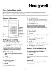
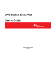
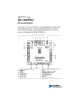
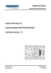
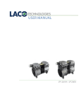
fg MORE BOARD USER'S MANUAL REV-11-1100-UM-00 Copyright © 2014 REV Robotics, LLC TABLE OF CONTENTS 1 2 MORE BOARD OVERVIEW ...................................................................................................................................................... 3 1.1 FEATURES ..................................................................................................................................................................... 4 1.2 KIT CONTENTS .............................................................................................................................................................. 4 FEATURE DESCRIPTION ........................................................................................................................................................ 5 2.1 2.1.1 2.2 2.2.1 2.3 SCREW TERMINALS...................................................................................................................................................... 5 USING THE SCREW TERMINALS ............................................................................................................................. 5 HEADERS ....................................................................................................................................................................... 6 PWM CONNECTIONS ................................................................................................................................................ 6 POWER RAILS ................................................................................................................................................................ 6 2.3.1 JUMPER SHUNTS ..................................................................................................................................................... 6 2.3.2 SOLDER JUMPERS ................................................................................................................................................... 7 2.3.3 ANALOG SIGNALS ..................................................................................................................................................... 7 2.4 PROTOTYPING AREA .................................................................................................................................................... 8 2.5 MOUNTING HOLES ........................................................................................................................................................ 8 APPENDIX A SCHEMATIC....................................................................................................................................................... 9 APPENDIX B DIMENSIONS ................................................................................................................................................... 11 LIST OF FIGURES Figure 1-1 More Board Picture ...................................................................................................................................................... 3 Figure 2-1 Header Pinouts ............................................................................................................................................................. 6 Figure 2-2 Solder Jumpers ............................................................................................................................................................ 7 Figure 2-3 Prototype Area Hole Pattern ....................................................................................................................................... 8 LIST OF TABLES Table 2-1 Screw Terminal Arrangement ....................................................................................................................................... 5 Table 2-2 Recommended Wire Size .............................................................................................................................................. 5 Table 2-3 Recommended Mounting Screw Sizes ........................................................................................................................ 8 REV-11-1100-UM-00 Copyright © 2014 REV Robotics, LLC 2 1 MORE BOARD OVERVIEW The REV Robotics More Board is a passive expansion board designed for the roboRIO MXP (myRIO Expansion Port). Every MXP signal is broken out to screw terminals and common 3-pin headers, effectively doubling the available Analog and Digital IO/PWM ports on the roboRIO. Figure 1-1 More Board Picture REV-11-1100-UM-00 Copyright © 2014 REV Robotics, LLC 3 1.1 FEATURES The REV Robotics More Board includes the following features: Access to all MXP signals o 3.5 mm screw terminals o 3-pin servo-style 0.1" headers o Single in-line 0.1" headers for UART, SPI, and I2C Configurable power rails o Pass-through MXP 3.3V or MXP 5.0V o Movable jumper shunts and solder jumpers o Separately select UART, SPI, I2C, and DIO VCC sources Prototyping area o Standard breadboard-style layout o 0.1" grid holes Mounting holes o 2 holes for roboRIO mounting, 4-40 x 3/16" screws o 4 holes for additional mounting options, #6 sized screws 1.2 KIT CONTENTS The REV Robotics More Board comes with the following: More Board Two 4-40 x 3/16" mounting screws REV-11-1100-UM-00 Copyright © 2014 REV Robotics, LLC 4 2 FEATURE DESCRIPTION The REV Robotics More Board includes a range of features designed to make expanding the roboRIO MXP port simple and easy. This section describes each of these features in detail. 2.1 SCREW TERMINALS Each MXP signal pin is broken out to a set of 3.5 mm screw terminals, labeled with their corresponding signal name. The signals are grouped by major pin function in the following order: Table 2-1 Screw Terminal Arrangement MXP Signal +5.0V +3.3V DIO0 DIO1 DIO2 DIO3 DIO4 DIO5 DIO6 DIO7 DIO8 DIO9 DIO10 GND UART.RX UART.TX More Board Screw Terminals Left Terminal (J3) Right Terminal (J2) 1 16 2 15 3 14 4 13 5 12 6 11 7 10 8 9 9 8 10 7 11 6 12 5 13 4 14 3 15 2 16 1 MXP Signal +5.0V +3.3V DIO11 DIO12 DIO13 DIO14 DIO15 GND +5.0V AIN0 AIN1 AIN2 AIN3 AOUT0 AOUT1 AGND 2.1.1 USING THE SCREW TERMINALS Using a small slotted screw driver, loosen the screw at the top of the terminal you wish to use. Insert stripped wire into the opening on the side of the terminal. While holding the wire in place, tighten the screw until the wire is held snug by the terminal. Please see Table 2-2 for the recommended wire size. Table 2-2 Recommended Wire Size Wire Type Wire Size (Minimum) Wire Size (Maximum) Stripped Length REV-11-1100-UM-00 Stranded (Recommended) Solid Core 28 AWG 16 AWG 5.5 mm (0.22") Copyright © 2014 REV Robotics, LLC 5 2.2 HEADERS Each MXP signal pin is broken out to sets of 0.1" pin-headers. Every Digital IO (DIO), Analog Input, and Analog Output is brought out to 3-pin headers with the standard servo-style pinout: [GROUND][POWER][SIGNAL]. Serial interfaces shared 2 with DIO, I C and SPI, are also brought out to single line headers. UART is only brought out in a single line header because it is not shared with any DIO. Each signal is labeled next to its corresponding header group. Figure 2-1 shows these pinouts. Figure 2-1 Header Pinouts 2.2.1 PWM CONNECTIONS PWM signals are shared with several DIO on the MXP. These signals, like all MXP signals, are passed through and broken out without any intermediate active circuitry. For example, these PWM connections can be used to safely connect motor controllers, keeping their PWM signals under control of the roboRIO. CAUTION Do not connect Servo Motors to the More Board. The MXP and the More Board are not designed to provide power to Servo Motors. Even though 5.0V or 3.3V is provided on the middle pin of the 3-pin headers, the required 6.0V is not brought out through the MXP and therefore not available on the More Board. Servos must be connected to the roboRIO PWM ports. 2.3 POWER RAILS The MXP can provide both 5.0V and 3.3V to connected expansion boards. Four separate rails exist on the More Board, 2 each with the ability to use the MXP 5.0V or 3.3V. These four rails are DIO VCC, I C VCC, SPI VCC, and UART VCC. Each rail has two methods of selecting the supplied voltage: a jumper shunt and a solder jumper. 2.3.1 JUMPER SHUNTS The 2-pin jumper shunts are installed on 3-pin headers and connect the middle pin to one of the outer pins. Move the jumper to the side labeled with the desired voltage. REV-11-1100-UM-00 Copyright © 2014 REV Robotics, LLC 6 2.3.2 SOLDER JUMPERS Next to each 3-pin power rail header is a set of two solder jumpers. These provide a more secure way to select the voltage rail, but require the use of a soldering iron. To select a voltage rail, first remove the jumper shunt. Then, on the solder jumper associated with the desired voltage label, flow a small quantity of solder onto the fork shaped pads so that the connection is made between the prongs. See Figure 2-2 for a before and after example of selecting 5.0V for DIO VCC using the solder jumper. CAUTION Take care not to short both solder jumpers. This can create a short between the 5.0V and 3.3V rails and damage the roboRIO. It is also recommended that you remove the 2-pin jumper shunt when using the solder jumpers to prevent the accidental shorting of the rails. See Figure 2-2 for examples of proper solder jumper usage. Solder Bead S Figure 2-2 Solder Jumpers 2.3.3 ANALOG SIGNALS The 5.0V rail is directly connected to the analog headers because the roboRIO's Analog to Digital Converter (ADC) measures between 0V and 5.0V. Analog ground (AGND) is broken out from the MXP and kept isolated from digital ground (GND). REV-11-1100-UM-00 Copyright © 2014 REV Robotics, LLC 7 2.4 PROTOTYPING AREA At the center of the More Board is a 16 x 16 0.1" grid prototyping area. The plated-through holes are arranged like a standard breadboard with bus strips and terminal strips. Six bus strips run vertically with two on the left, two in the center, and two on the right. These bus strips are electrically connected through the entire column (1 - 16). There are 16 5-pin terminal strips on each side of the center bus strips (A-E and F-J). The 5 pins are electrically connected in each terminal strip. Figure 2-3 shows the prototyping area hole pattern. Figure 2-3 Prototype Area Hole Pattern By default, the bus strips are not connected to power or ground. 5.0V, 3.3V, and ground must be connected by soldering a connection between the power pads (located at the bottom of the prototype area) and the bus strips. 2.5 MOUNTING HOLES The More Board has 6 mounting hole locations throughout the board: 2 roboRIO mounting holes and 4 general mounting holes. These mounting holes give flexibility in mounting the board, either mounted directly on the roboRIO or externally using the REV Robotics MXP Extension Cable (REV-11-1118). Please see APPENDIX B DIMENSIONS for the mounting hole placements. Table 2-3 shows the recommended mounting screw sizes. Table 2-3 Recommended Mounting Screw Sizes Mounting Hole roboRIO General Mounting REV-11-1100-UM-00 Quantity 2 4 Recommended Screw Size 4-40 x 3/16" Machine Screw #6 Machine Screw Copyright © 2014 REV Robotics, LLC 8 APPENDIX A SCHEMATIC Appendix A shows the schematic for the REV Robotics More Board. REV-11-1100-UM-00 Copyright © 2014 REV Robotics, LLC 9 MXP Connector Right Screw Terminals Left Screw Terminals MXP_SIGNALS MXP_SIGNALS +5.0V +3.3V J3 J2 +3.3V +5.0V 1 2 3 4 5 6 7 8 9 10 11 12 13 14 15 16 DIO0/PWM0 DIO1/PWM1 DIO2/PWM2 DIO3/PWM3 DIO4/SPICS DIO5/SPICLK DIO6/SPIMISO DIO7/SPIMOSI DIO8/PWM4 DIO9/PWM5 DIO10/PWM6 UART.RX UART.TX DIO11/PWM7 DIO12/PWM8 DIO13/PWM9 DIO14/I2CSCL DIO15/I2CSDA +5.0V AI0 AI1 AI2 AI3 AO0 AO1 CON-TERM-SCREW-16P-3MM5-TH-ED555/16DS +5.0V +3.3V +5.0V 16 15 14 13 12 11 10 9 8 7 6 5 4 3 2 1 J1 AI0 AI1 AI2 AI3 DIO0/PWM0 DIO1/PWM1 DIO2/PWM2 DIO3/PWM3 DIO4/SPICS DIO5/SPICLK DIO6/SPIMISO DIO7/SPIMOSI DIO8/PWM4 DIO9/PWM5 DIO10/PWM6 CON-TERM-SCREW-16P-3MM5-TH-ED555/16DS +3.3V AGND JP36 1 3 5 7 9 11 13 15 17 19 21 23 25 27 29 31 33 AO0 AO1 2 4 6 8 10 12 14 16 18 20 22 24 26 28 30 32 34 AGND UART.RX UART.TX DIO11/PWM7 DIO12/PWM8 DIO13/PWM9 DIO14/I2CSCL DIO15/I2CSDA CON-HDR-2X17-0100-THS-DBCOGJ254DS34 JP35 JP34 DIO_VCC +5.0V +3.3V JP6 DIO_VCC JP4 I2C_VCC DIO14/I2CSCL DIO15/I2CSDA JP5 DIO_VCC +5.0V +3.3V DIO0/PWM0 DIO1/PWM1 DIO2/PWM2 DIO3/PWM3 DIO8/PWM4 DIO9/PWM5 DIO10/PWM6 DIO11/PWM7 DIO12/PWM8 DIO13/PWM9 Prototype Area JP45 JP44 JP43 SPI_VCC DIO4/SPICS DIO5/SPICLK DIO6/SPIMISO DIO7/SPIMOSI +5.0V +3.3V AI0 AI1 AI2 AI3 JP1 +5.0V JP3 +3.3V +5.0V UART_VCC AGND UART.TX UART.RX +5.0V AO0 AO1 JP2 DESIGNER REVISION DATE DAY A1 11/14/2014 PROJECT More Board DESCRIPTION AGND MXP Breakout Board FILENAME moreboard-revA1.sch WWW.REVROBOTICS.COM PART NO. RR-MORE-BD-A1 SHEET 1 OF 1 APPENDIX B DIMENSIONS Appendix B shows a dimensional drawing of the REV Robotics More Board. All dimensions are in inches. REV-11-1100-UM-00 Copyright © 2014 REV Robotics, LLC 11