1
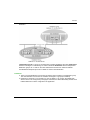
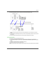
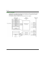
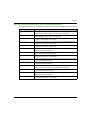
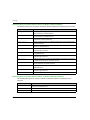
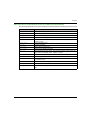
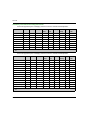
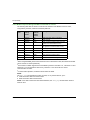
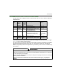
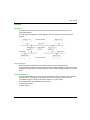
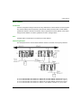
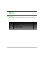
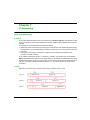
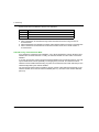
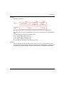
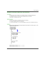
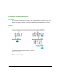
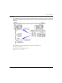
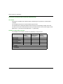
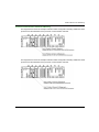
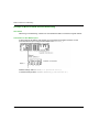
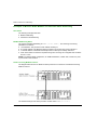
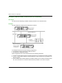
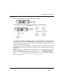
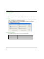
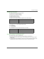
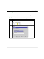
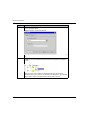
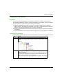
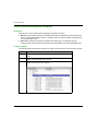
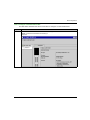
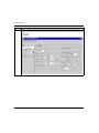
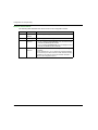
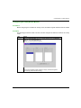
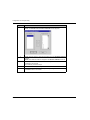
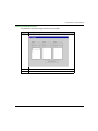
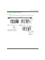
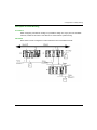
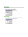
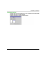
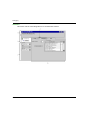
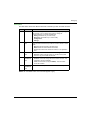
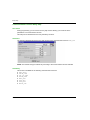
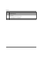
Debugging Description The table below shows the different elements of the debug screen and their functions. Label Element Function 1 Tabs The tab in the foreground indicates the mode in progress (Debug for this example). You can select each mode by clicking the corresponding tab. The modes available are: Debug (accessible only in online mode), Diagnostic (accessible only in online mode), Configuration, Settings. 2 Module area This area displays the abbreviated module indicator. There are three indicators that provide the module’s status in online mode: RUN indicates the module’s operating status, ERR indicates an internal fault in the module, I/O indicates a fault from outside the module, or an application fault. 3 Channel area This area is used to select the channel to be debugged: Channel: module channel number. To the left of the symbol there is a copy of the CHx channel LED. 4 General parameters area This area shows the communication channel parameters: Function: shows the configured communication function. This information cannot be modified. Task: shows the task (configured MAST). This information cannot be modified. 5 Mode parameters area This area contains the parameters of the mode selected by the tab. NOTE: All unavailable LEDs and commands appear in gray. 35010500 10/2014 143