1
1 The Series 307 Vacuum Gauge Controller
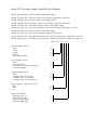
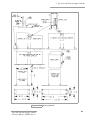
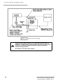
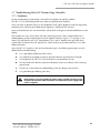
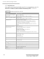
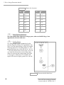
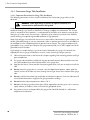
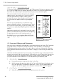
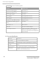
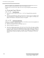
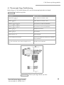
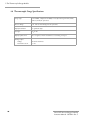
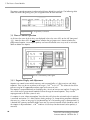
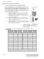
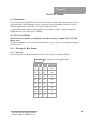
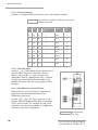
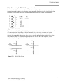
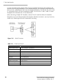
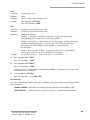
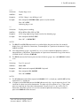
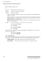
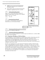
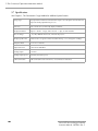
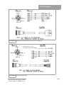
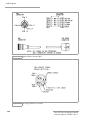
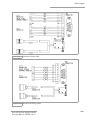
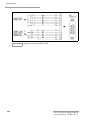
Figure 1-11 Remote Control Connector.
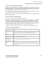
1.5 Theory of Operation
1.5.1 Ion Gauge Theory
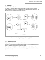
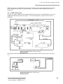
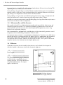
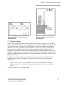
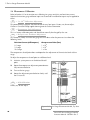
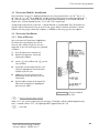
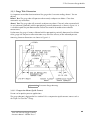
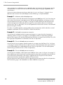
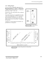
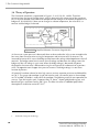
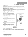
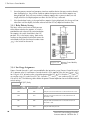
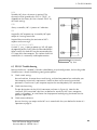
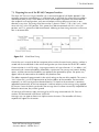
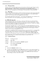
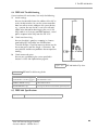
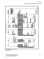
The functional parts of a typical ionization gauge are the filament (cathode), grid (anode) and ion
collector, shown schematically in Figure 1-12. These electrodes are maintained by the gauge
controller at +30, +180, and 0 Vdc, relative to ground, respectively.
The filament is heated by direct current to such
a temperature that electrons are emitted, and
accelerated toward the grid by the potential
difference between the grid and filament. All
the electrons eventually collide with the grid,
but many first traverse the region inside the
grid one or more times.
Figure 1-12 Ion Gauge Schematic.
When an energetic electron collides with a gas molecule, an electron may be dislodged from the
molecule, leaving it with a positive charge. Most ions are then accelerated to the collector. The rate
at which electron collisions with molecules occur is proportional to the density of gas molecules,
and hence the ion current is proportional to the gas density (or pressure, at constant temperature).
The amount of ion current for a given emission current and pressure depends on the ion gauge
design. This gives rise to the definition of ion gauge “sensitivity”, frequently denoted by “K”:
K = ion current / (emission current x pressure)
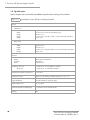
Bayard-Alpert type gauges typically have sensitivities of 10/Torr when used with nitrogen or
atmosphere. Sensitivities for other gases are given in Section 2.3 on page 38.
The ion gauge controller varies the heating current to the filament to maintain a constant electron
emission, and measures the ion current to the collector. The pressure is then calculated from these
data.
29
Series 307 Vacuum Gauge Controller
Instruction Manual - 307024 - Rev. C