1
GDANSK UNIVERSITY OF TECHNOLOGY
FACULTY OF ELECTRICAL AND CONTROL
ENGINEERING
STEPPING MOTOR CONTROLLING BY USING ARM
MICROPROCESSOR
AUTOR:
Chi Kin Lao
SUPERVISOR:
dr inż. Jarosław Guziński
Gdansk 2012
Global Affairs Office
ACKNOWLEDGEMENT
Thanks IAESTE, Faculty of Electrical and Control Engineering of Gdansk University of
Technology and Global Affairs Office for offer me this internship.
Thanks my supervisor Dr. Guzinski for his great support. It was very nice to work with
him.
Thanks Dr. Kevin Hung for writing me the recommendation letter.
Thanks my FYP partner Mr. U Kin Che and my roomate Mr. José Rua for their
knowledge in programing.
1
Table of Content
Acknowledgement -------------------------------------------------------------------------------------1
Abstract ---------------------------------------------------------------------------------------------------3
1. Introduction -----------------------------------------------------------------------------------------3
2. Project kept in the lab ----------------------------------------------------------------------------4
3. The control algorthim ----------------------------------------------------------------------------5
4. Current control ------------------------------------------------------------------------------------6
5. Immplementation ---------------------------------------------------------------------------------8
6. Future development ----------------------------------------------------------------------------10
7. Conculsion -----------------------------------------------------------------------------------------10
8. Reference ------------------------------------------------------------------------------------------11
9. Appendix I – The main.c Program of the Developed Embedded Programs --------12
10. Appendix II - Create Embedded Programs for Testing Step by Step -----------------18
2
Abstract - In this laboratory training, the basics of stepper motor and its modern
controls were learnt. An AMR microprocessor broad (controller) was offered as a
pulse source to control a stepper motor with driver that is a project kept in the lab
[1], and the embedded control programs were written in C language in µVision 4
platform.
1. Introduction
Motors play an important role in automation, motor types with different structure
and control methods can be divided into DC motors, AC motors, servo motors and
stepper motors. In terms of power consumption, DC and AC motors have better
power output. However, on control accuracy view, servo motors and stepper motors
are the better choice.
Stepper motor or pulse motor, unlike AC motors, DC motors, and servo motors.
Because of high torque at low speed, high holding torque at rest, start/stop and
reversing response is good, and the rotation angle is proportional to the input pulse
and low angle error characteristics, the use of open-loop control to achieve
closed-loop control of the demand for high-precision angle and high-precision
positioning.
Since the drive is simple, accurate positioning and control is open-loop, so it’s often
be used in variety of precise positioning applications, such as on printer, plotter,
floppy drive, and other devices.
The objective of this training is to understand the knowledge of stepper motor and
its control methods, and try to develop an embedded control programs work with
ARM microprocessor.
3
2. Project Kept in the Lab
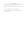
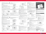
[1] The stepper motor of the project kept in the lab is model EDS-20. Inside it,
current can flow in a band in only one direction during operation. Unipolar control is
thus imposed by the structure of the motor itself. The bands (totally 4) combination
of the motor is illustrated in Fig.1.
Fig.1. Bands combination of EDS-20 engine
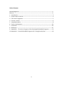
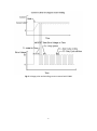
[1] The following figure shows a typical control system of a stepper motor. The driver
in the original project was already well developed, and the main task of this training
is to use only one ARM processor broad to generate pulse signals to the driver to
control the motor.
Pulse Source
Control Logic
Driver
Stepper Motor
Power Supply
Fig.2. Typical control system of a stepper motor
The next two sections will discuss the basic control theories on this unipolar motor.
4
3. The control algorithm
[1] For the control of EDS-20 engine, the controller was designed to implement the
algorithm work for 2/4 which is also known as two-phase. This algorithm is specific
to unipolar motors reluctance. The ideal 2/4 switching of four-band motor is
characterized by the fact that 2 bands are powered and 2 bands remain in open
circuit condition at anytime, while the numbers of possible combinations of the
powered bands are 4. Figure 3 [2] presents the ideal case of full step drive (2/4
switching).
Fig.3. Idealized process algorithm 2/4
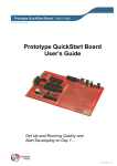
[1] In fact, during the implementation of the algorithm in motor windings will be
slightly different from those shown in Figure 11. Deformation of ideal waveforms is
caused by the presence of a delay time of rising and falling current in the individual
bands. This phenomenon always appears to decrease the frequency of jumps. The
course of the actual algorithm, 2/4 is shown in Figure 4.
Fig.4. The actual course of the algorithm 2/4
5
4. Current Control
As we know, the instantaneous torque generated in each band depends on the
current flowing though in the band rather than the voltage drop on the band [5].
Each band in stepper motor is characterized by a resistance and inductance.
Inductance makes the motor winding oppose current changes, and every RL circuit is
characterized by a time constant τ = L / R, therefore limits high speed operation.
[1] The original project already employed the control method “L/Rn” that reduces
the time constant by series a resistor to the winding. Such method is simple enough
but with a drawback on the heat energy consumption of the series resistor.
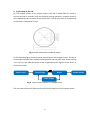
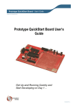
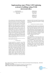
There is a further current control method, so called pulse width modulation (PWM)
technic, which normally using with microprocessor according to its highly integration
and high speed operation and detection. PWM can achieve high dynamic together
with reasonable power consumption. The method is to apply high voltage to the
driver and a feedback path from the motor resistor to the ADC of the processor.
When signal pulse comes to one of transistor input terminal of a winding (Figure 5
[1]), according to the high supply voltage to the driver, the current flowing through
the winding will increase and reach to working value very fast (high dynamic), but
once the winding current or the voltage of the motor resistor exceed some value
(normally below the rating current), the processor will trigger to switch off the signal,
so the winding current will drop down, then similarly, once the winding current or
the voltage of the motor resistor lower than some value, the processor will trigger to
switch on the signal, so that to maintain the winding current around a expected
value (Figure 6 [3]) during pulse period.
Fig.5. Commutator Connection of EDS-20
6
Fig.6. Voltage pulse and winding current control with PWM
7
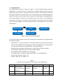
5. Implementation
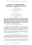
The implemented system is shown as Figure 7. [4] The ARM controller broad is
supplied at 9 V, and the driver is powered by a voltage supply which will directly
affect the torque and the maximum speed of the motor. The controller will keep
listening to the buttons pressed by the user and generates the corresponding pulse
signal to the driver, then the driver will converse the input signal to be large signal to
control and supply the rotation of the stepper motor. Also, there is a LCD displaying
information to the user. According to time limitation, the system was built without
current control feedback, but the building method is discussed later in the future
development.
ARM Controller
Driver
Stepper Motor
+9V Supply
Power Supply
Fig.7. Overall system blocks diagram
To realize the above system control, the connections and settings of the ARM broad
are shown as below:
- Output P0.8...12 of the processor as control pulse PINs is connected to the Inputs
-
+5V, D0...D3 of EDS-20 correspondingly. (Note that ON/OFF of the winding LEDs
A, B, C and D on EDS-20 is inversed to D0...3 correspondingly.)
Functions and its symbols of the buttons or input PINs are shown as table I
P0.27 (AIN0) as ADC input PIN for motor rotational delay
P0.29 (AIN2) and P0.30 (AIN3) is for LCD display
For jumpers JP11…14, KB1…4 connected to KB11…14 correspondingly
Jumper J10 for button “INT1” is on
Jumper “ANA_EN” for “AIN0” is on
Table I
Functions and its symbols of the buttons on the ARM broad
Button
S1
S2
S3
Function
Continuously
Continuously Counterclockwise Clockwise
counterclockwise clockwise
rotation
rotation
rotation
rotation
Stop
Symbol
<<
>>
<
>
X
PIN
P0.4
P0.5
P0.6
P0.7
P0.14
8
S4
INT1
With the connection and settings mentioned above, the embedded programs were
written, inside it the ADC and LCD display function is base on the ARM broad
example. The following is the description of the “main.c” in “Appendix I”:
Every time the program starts to run, it will display the stepper motor name
“EDS-20” on the LCD and only power band A and band B in the motor at the
beginning, then display functions of the buttons (Table I), and then after reading the
variable resistance by the on chip ADC, motor rotational delay which depends on this
reading will be displayed on the LCD. At this moment, the processor will keep
listening to the buttons pressed by the user.
-
If “INT1” is pressed, functions of the buttons will display again and last for few
second, then again keep listening to the buttons.
-
If “S1” or “S2” is pressed, the motor will rotate in counterclockwise or clockwise
direction continuously with every new ADC delay reading. During the delay
(written in for-loop), the processor will keep listening to the stop button “INT1”.
(The rotation can be stop immediately as the processer will spend most of the
time in the for-loop and the other lines in the program will be processed within a
very short time. The performance of this stopping almost achieves to employ
external interrupt.) If “INT1” is pressed, it will do the same process as mentioned
before. During the non-delay period, if “S1” was pressed before, it will listen to
“S2” for reverse rotation, and vice versa for “S2” was pressed before.
-
If “S3” or “S4” is being pressed, the motor will keep rotating in counterclockwise
or clockwise direction with every new ADC delay reading until the button is
released. After release pressing, if “INT1” is pressed, it will do the same process
as mentioned before.
9
6. Future Development
The embedded programs developed in this training contain basic rotational and
speed controls on the motor, and with a LCD displaying feature. User can make the
motor rotates or stops by pressing the buttons on the controller and can view the
information displayed on LCD.
The following would like to give some recommendation to have further advance
control on the motor:
a) According to safety reason, we always want the ARM processor can response to
us to stop the motor at any time. External interrupt function can be applied to
achieve this requirement.
b) The motor rotational delay depends on the resistance reading from on chip ADC
and also the processor speed. Timer interrupt function can be combined with the
ADC to have precise timing control.
c) PWM technic can be applied to achieve high dynamic in the motor. It can be
realize by applying voltage feedback from the resistor “Rm” at the driver to one of
the on chip ADCs. There are totally 4 ADCs with analog input PIN namely
AIN0…3(P0.27…30) in the processor. As mentioned before, AIN0 is used for the
motor rotational delay, and both of P0.29 and P0.30 are employed for the LCD
display. The only unused ADC PIN in this program is AIN1 (P0.28), but note that
the jumper “NTC_EN” (J5) must be switched OFF so that the AIN1 is really
available. To measure the voltage on Rm correctly, the grounds of the driver and
the processor should be connected, and another end of Rm should be connected
to P0.28.
Conclusion
In this 6 weeks training, stepper motor and its control algorithms were learnt. A
control program for stepper motor EDS-20 was designed with C langue in µVision 4
and well tested by using ARM microprocessor LPC2129. The controls basically
include speed control, clockwise and counterclockwise rotations, reversing rotation,
stop rotating and LCD display function. Future developments employing external
interrupt and timer interrupt in processor, and PWM technic for advance control
were given in the last section.
10
Reference
1. Krzysztof Jendraszek: Projekt i wykonanie przekształtnika do mikroprocesorowo
sterowanego silnika skokowego, Gdansk 2008
2. Stepper motor from WIKI: http://en.wikipedia.org/wiki/Stepper_motor
3. Stepper motor and control:
http://www.stepperworld.com/Tutorials/pgCurrentControl.htm
4. LPC2129 user manual:
http://www.keil.com/dd/docs/datashts/philips/user_manual_lpc2119_2129_2
194_2292_2294.pdf
5. Stepper motor basics: http://library.solarbotics.net/pdflib/pdf/motorbas.pdf
11
Appendix I – The main.c Program of the Developed Embedded Programs
/******************************************************************/
/* ZL5ARM Controller of the stepping motor EDS-20
*/
/* Inputs +5V and D0...D3 of EDS-20 is connected to P0.8...12 correspondingly */
/* ON/OFF of LEDs A, B, C and D on EDS-20 is inverse to D0...D3 correspondingly */
/******************************************************************/
#include <LPC21xx.H>
#include "const_bit.h"
#include "lcd.h"
#define del_l 0x400000
#define del_s 0x10000
unsigned int step_val = 1;
// Totally 4 step values: 1 to 4, represent the states of D0 to D3
void run (void);
// The core function for controlling
void delay_ADC (void);
// Delay of the motor retation depends on the ADC reading
void delay (unsigned int del_time); // Delay for LCD diaplay
void stepping (int step_val);
// Only D0D1, D1D2, D2D3 or D3D1 will set "0" at any moment
int clockwise (int step_val);
// Stepping changing for clockwise rotation
int counterclockwise (int step_val); // Stepping changing for counterclockwise rotation
void LCD_Hex(int hex);
// Hex digit display on the LCD
int main (void)
{
// Define in/output
IODIR0 = 0xFF00FF00;
IODIR1 = 0x00FF0000;
PINSEL1 &= !(BIT26 | BIT27 | BIT28 | BIT29);
PINSEL1 |= BIT22;
ADCR = 0x002E0401;
// AC: 10 bit AIN0 @ 3MHz
LCDInit();
LCDSendByte(0x01,0);
// clrscr
12
delay(del_s);
// Display the stepping motor name * EDS-20 * in LCD
LCDSendByte(' ',1); delay(del_l);
LCDSendByte(' ',1); delay(del_l);
LCDSendByte(' ',1); delay(del_l);
LCDSendByte('*',1); delay(del_l);
LCDSendByte(' ',1); delay(del_l);
LCDSendByte('E',1); delay(del_l);
LCDSendByte('D',1); delay(del_l);
LCDSendByte('S',1); delay(del_l);
LCDSendByte('-',1); delay(del_l);
LCDSendByte('2',1); delay(del_l);
LCDSendByte('0',1); delay(del_l);
LCDSendByte(' ',1); delay(del_l);
LCDSendByte('*',1); delay(del_l);
delay(del_l);
// Initialize the outputs D0D1D2D3 = "0011"
IOSET0 = 0x0000FF00;
IOCLR0 = 1<<9;
IOCLR0 = 1<<10;
run ();
}
/////////////////////////////////////////////////////////////
void run (void) {
LCDTextXY(0, 1, "1<< 2>> 3< 4> 5X"); // Display functions of the buttons (S1, S2, S3, S4, INT1)
delay(8*del_l);
LCDTextXY(0,1, "
");
delay_ADC (); // Show the current delay value of motor rotation
// Loop function for buttons S1 to S4 and INT1
while (1)
{
// When S1 connected to P0.4
13
if( !(IOPIN0 & 0x00000010))
{
while (1) { //Rotate continuously
// Changing step value for clockwise rotation
step_val = counterclockwise (step_val);
stepping (step_val);
if( !(IOPIN0 & 0x00000020)) {break;} // Break and rotate in counterclockwise
when button INT1 is pressed
}
}
// When S2 connected to P0.5
else if( !(IOPIN0 & 0x00000020))
{
while (1) {
step_val = clockwise (step_val);
stepping (step_val);
if( !(IOPIN0 & 0x00000010)) {break;} // Break and rotate in clockwise when button
INT1 is pressed
}
}
// When S3 connected to P0.6
else if( !(IOPIN0 & 0x00000040))
{
step_val = counterclockwise (step_val);
stepping (step_val);
}
// When S4 connected to P0.7
else if( !(IOPIN0 & 0x00000080))
{
step_val = clockwise (step_val);
stepping (step_val);
}
else if( !(IOPIN0 & 0x00004000)) {
14
run ();
}
} // While end
}
// Stepping motor steps to one of the 4 steps
void stepping (int step_val) {
if (step_val == 1)
{
IOSET0 = 0x0000F900; //Set both D2 and D3 "1"
IOCLR0 = 0x00000600; //Set both D0 and D1 "0"
}
else if (step_val == 2)
{
IOSET0 = 0x0000F300; //Set both D0 and D3 "1"
IOCLR0 = 0x00000C00; //Set both D1 and D2 "0"
}
else if (step_val == 3)
{
IOSET0 = 0x0000E700; //Set both D0 and D1 "1"
IOCLR0 = 0x00001800; //Set both D2 and D3 "0"
}
else if (step_val == 4)
{
IOSET0 = 0x0000ED00; //Set both D1 and D2 "1"
IOCLR0 = 0x00001200; //Set both D0 and D3 "0"
}
delay_ADC (); // Delay the motor rotation and display the delay value
}
void delay_ADC (void) {
unsigned int val;
int t;
ADCR |= 0x01000000;
do
{
// start converting AC
15
val = ADDR;
// read the conversion result
} while ((val & 0x80000000) == 0);
ADCR &= ~0x01000000;
val = (val >> 6) & 0x03FF;
// wait for the end of the conversion of AC
// AC conversion end
// Display the reading value
LCDTextXY(0,1, "AIN0 = 0x");
LCD_Hex((val >> 8) & 0x0F);
LCD_Hex((val >> 4) & 0x0F);
LCD_Hex(val & 0x0F);
// 1st digit
// 2nd digit
// 3rd digit
// Delay for the motor rotation
for(t = 0; t < (val*1000+0x20000); t++) {
if( !(IOPIN0 & 0x00004000)) {
run ();
}
}
val = (val >> 2) & 0x00FF;
IOCLR1 = 0x00FF0000;
IOSET1 = 0x00FF0000 & (val << 16);
// LED off
// 8 most significant bits of the conversion to LED
}
int clockwise (int step_val) {
switch (step_val) {
case 1:
return 4;
case 2:
return 1;
case 3:
return 2;
case 4:
return 3;
}
}
int counterclockwise (int step_val) {
switch (step_val) {
16
case 1:
return 2;
case 2:
return 3;
case 3:
return 4;
case 4:
return 1;
}
}
void delay (unsigned int del_time)
{
unsigned int i;
for(i = 0; i < del_time; i++);
}
void LCD_Hex(int hex)
{
if (hex > 9) LCDSendByte('A' + (hex - 10),1);
else
LCDSendByte('0' +
hex,1);
}
17
Appendix II - Create Embedded Programs for Testing Step by Step
The embedded programs were written in C langue in the microcontroller
development kit (MDK) “µVision 4”, and the programs were compiled and tested on
the processor in HEX format by using the programming tool “Flash Magic” via serial
port. The following will tell how to do step by step from downloading µVision 4 to
testing the program on processor.
The below link is the official download web page of µVision 4:
https://www.keil.com/demo/eval/arm.htm
The programming tool “Flash Magic” can be found from another official website as
shown as the following:
http://www.flashmagictool.com/
After download and install the software, you may start to create a new project. You
can view and download the official “Getting Started” guide in PDF format from the
below link:
http://www.keil.com/product/brochures/uv4.pdf
At page 75, chapter 6 is talking about how to create embedded programs in detail.
Don’t forget to generate the HEX file for testing on the processor, and it can be apply
from the following steps with figures:
I) In the Project Menu -> Options for Target…
18
II)
A new window will pop up, then go to “Output”, and then tick the box “Create
HEX File”
III) Then go to “Linker”, and then tick the box “Use Memory Layout from…”
19
Then after finish writing programs and build it without any error, the HEX file can be
compiled by using Flash Magic. The following is the compiling steps:
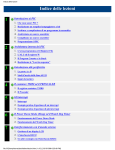
In Step 1
I) Select the testing processor (in this case is processor LPC2129)
II) Choose the appropriate COM Port (in this case is COM 3)
III) Set the Baud Rate of the COM Port to 19200
IV) Select Interface to be None (ISP)
V) Set Oscillator frequency to 12 MHz which is the same as the clock of LPC2129
In Step 2
VI) Tick the box “Erase all Flash+Code Rd Prot”
In Step 3
VII) Apply the location of the HEX file for compile
In Step 5
VIII) Click the “Start” button. (Remember to connect the computer and COM0 of the
ARM broad via serial port; power the ARM broad; the jumper J7 on the ARM
broad should be on ISP as we have chosen ISP interface before, and COM
port on computer should be free for use or without access by other software
else)
Finally, you will see if the program works normally or not.
20