1
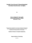
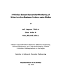
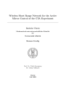
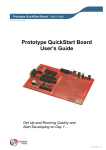
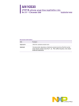
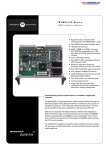
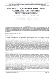
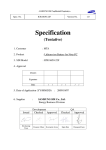
Deepak Chamarthi et al. / International Journal on Computer Science and Engineering (IJCSE) Research on Compound Display Connections to ARM Based Processors Deepak Chamarthi M.Tech. Student, Department of ECE Sasi Institute of Technology and Engineering ,Tadepalligudem [email protected] T J V Subrahmanyeswara Rao M.Tech. Associate Professor, Department of ECE Sasi Institute of Technology and Engineering ,Tadepalligudem [email protected] Abstract - An electronic display is used to present data visually by transmitting images as output device. Visual displays generate visual information according to the electrical input signal either by generation of light or modulation of available light. This is of two types analog or digital. Now-a-days usage of many displays gaining wide acceptance in many areas of applications like Workstations, Information Broad casting, video conferencing etc. connecting two or more displays to a personal computer is possible by adding extra hardware and accordingly software like device drivers which are often expensive. Power supply requirement for this dedicated task is almost same as personal computer which runs with various applications. In this paper we have implemented multiple display connection modes to an ARM processor and achieved great reduction of power supply for this dedicated task. Keywords- Display modes; DCSP; keil; Multi-monitors; switchable displays; I. INTRODUCTION ARM9 processor is 32-bit RISC developed by ARM Holdings. The relative simplicity of ARM processors make them suitable for low power applications. As a result, they have become dominant in the mobile and embedded electronics market. Approx. 90% of embedded devices like music players, digital cameras, mobile phones, hand held game consoles, high end calculators etc. use ARM as processor[3]. So we have chosen ARM as platform to implement compound displays to attain more generality. Increasing the no. of displays has the primary advantage of increase in the area available for computer programs running on single display. Windows, X-server and Mac OS supports simultaneous use of multiple monitors, but it depends on the proprietary video drivers. Multiple monitoring is the inexpensive way of improving computer usage. The resulting area is limited to some parameters like resolution, size, no. of monitors. The operating system has to manage the display’s resolution independently. II. VIDEO OUTPUT Video output on a computer is generally by a video graphics card, which consists of different types of video connectors (depends on the category of card) or many times it is integrated into chipset. If we need to implement a dual-head display on personal computer, chipset should possess integrated video outputs. Personal computer should always power up to signal the monitors and it utilizes the total power. The power consumption of PC varies depending on the hardware. A typical 1.7GHz, Pentium 4 processor takes approx. 110W to boot up[12]. Present day applications demands more number of displays to visualize the information to large number of audience or to present data more effectively, but this requires a dedicated processor with every monitor connected to it. This can be implemented with the use of a sufficient GPU, which can drive such no. of ISSN : 0975-3397 Vol. 3 No. 9 september 2011 3194 Deepak Chamarthi et al. / International Journal on Computer Science and Engineering (IJCSE) displays, but this setup demands much more CPU power and so it is not at all appreciable for long running applications or permanent visualization environment. Use of GPU for long time may also cause Hardware hang or damage. So an intelligent idea of escaping from these situations is possible by allocating a separate processor to this dedicated application. Using ARM9 as processor we can interface different types of displays to achieve compound display connections [4]. The number of displays that can be connected to an ARM9 depends on availability of the RAM. The physical video connectors are used to connect different displays. Different displays have their own merits and demerits, the hardware driver circuit has to design [6].It depends on the type of display connector we are going to use. There are many types of physical video connector s to choose from, which include Composite video, Component video, S- video, VGA, DVI, HDMI, DP, mini DP etc. All these connectors use different protocols for connections. Since Visual Graphic Array [VGA] is most enormously using display connector type from many years and has wide acceptance at many areas, we have chosen to extend display through VGA [8]. The implementation diagram is as shown in fig (i). Monitor is connected to the processor through VGA connector and a dedicated hardware driver circuit is provided to drive the video output to the connected monitor. Fig (i) Conceptual Diagram with ARM9 Processor The VGA display has 15 pins which has the pin configuration [8] as in Table (i) Table (i) VGA Pin configuration Connection of two or more displays can be possible in different modes like same image is displayed in all monitors or the image can be extendable or distributed across all the monitors. Out of different modes of connections cloning of image is most preferable and has more demand in commercial marketing. This type of cloning displays is useful in displaying same information to large group of people and also useful to present same display at distinct places. General usage of these types of displays is at public places like Railway stations, ISSN : 0975-3397 Vol. 3 No. 9 september 2011 3195 Deepak Chamarthi et al. / International Journal on Computer Science and Engineering (IJCSE) Aitports, Theme parks, Stock exchanges etc. Here two or more displays shows the same information. This is as shown in fig(ii)(b) LCD stands for Liquid Crystal Display. LCD is finding wide spread due to its unique features like Incorporation of a refreshing controller into the LCD, thereby relieving the CPU of the task of refreshing the LCD and Ease of programming for characters and graphics .LCDs are part of our life starting from cell phones, media players and car navigation systems GPS. LCD takes important part in medical environment, where visual information may be critical. As shown in the figure (i) the hardware driver circuit drives converts LCD signal to VGA. Switchable display option can be provided to have switching actions between the two displays. According to the user input the switching action is performed. In this case any one of either LCD or VGA will be in the enable state at a particular time as in the fig(ii)(c). III. DISPLAY MODES Display modes are the different possible ways of connecting available screens. These methods of connecting more number of screen is shown in fig(ii) . Twin display mode fig(ii)(c) is most common mode of connecting multiple screens. In this mode two screens are having the same information. Twin display mode is useful to present same data at distant places. Since all screens have the same data, this mode is very much useful to display information like time, score update etc. Large display mode is to share the information among the all connected screens. With this mode it is possible to view data with increased resolution without use of physical large display. Creating a virtual large display with added resolution is possible with this mode as shown in fig (ii) (d). In practice it is beneficial to distribute data among more number of display than showing it on one large screen, which also helps for trouble shooting and easy identification of fault without loss the entire information. Independent display mode is the most useful manner in mobile applications. In this mode all screens can be connected individually to the processor where different processes are displayed on different screens. This display mode is useful to present different information or data from the input on different screens at same time as no screen has same information as in fig(ii) (e). Fig(ii) Display Modes The algorithm for the display switching and configuration is shown in the figure (iii). When user wants to apply switchable mode then the other modes are not applicable. Switchable mode suits for two monitors only. Switching of monitors between LCD and VGA enables only one display at a time. When switchable monitors are not enabled, then use has choice of selecting different modes of display as explained above. ISSN : 0975-3397 Vol. 3 No. 9 september 2011 3196 Deepak Chamarthi et al. / International Journal on Computer Science and Engineering (IJCSE) IV.SOFTWARE SECTION A. Algorithm: The below shown algorithm in fig (iii) is a model of implementing the different types of display modes. Switching among different types of display modes is absolutely based on the user input as shown in the below flow chart. Control input (CIP) is used to carry the user information. The feasible modes of displaying data among various screens are all depends upon the user input. Fig(iii) Algorithm of Display modes switching When switchable monitors option is enabled, then user have choice of selecting either LCD or VGA display depends on the control input (CIP) at any point time according to the demand. An API named DCSP (Display Control System Protocol) is designed to interact with driver to perform these tasks. The UI of the DCSP is as shown in fig(iv) This User Interface consists of different functionalities to implement display modes. B.Program Model: We took two samples 2x16 LCDs to implement the above algorithm on ARM7processor to describe the behavior of feasible display modes. ARM7 has ARMv4T architecture, completely suits to realize compound connections. The below sample snippet of code describes the interfacing and possible modes to implement compound display modes. The usage of each function is explained with in comments beside it. (i) Serial data reading unsigned char recvmsg()// serial reading { unsigned char x; while((U1LSR&0X01)!=0X01); //checking for character form com1 x=U1RBR; //store the character to variable x return x;} ISSN : 0975-3397 Vol. 3 No. 9 september 2011 3197 Deepak Chamarthi et al. / International Journal on Computer Science and Engineering (IJCSE) This program is for serial communication, which checks for a character form com1 and store the character to assigned variable. (ii) LCDs interfacing void lcdinit1(unsigned int x)// to send commands { IOCLR0=0x00FFFFFF; IOSET0=x; //IOSET0=IOSET0<<16; IOCLR0=0x00004000; //RS // IOSET0=x; IOSET0=0x00008000; //EN delay(); IOCLR0=0x00008000;} //EN void lcddata1(unsigned char y)// to send data { IOCLR0=0x00FFFFFF; IOSET0=y; // IOSET0=IOSET0<<16; IOSET0=0x00004000; //IOSET0=y; IOSET0=0x00008000; delay(); IOCLR0=0x00008000;} Another program module as above is used for other LCD to interface with processor. It is also has functionalities for LCD initialization and is used to send data and commands. (iii) Serial Port Enable from UI //enable serialport1(serialport1,open()) buf(0) = "!"//declare as char SerialPort1.Write(buf, 0, buf.Length) tx = TextBox1.Text//where we enter the text buf = tx.ToCharArray() SerialPort1.Write(buf, 0, buf.Length) (iv) Mode selection while(1) { if(recvmsg()=='!') //single display { lcdinit1(0x80); for(i=0;k!='\0';i++) {k=recvmsg(); lcddata1(k);}} We assigned different special symbol to each mode to recognize the user choice easily. So when ever user enters the special characters as stated above it will redirect to respective mode. The code snippet for different modes is demonstrated below. ISSN : 0975-3397 Vol. 3 No. 9 september 2011 3198 Deepak Chamarthi et al. / International Journal on Computer Science and Engineering (IJCSE) Fig(iv) Application Functionality //Twin Display Mode if(recvmsg()=='@') //twin display { lcdinit1(0x80); lcdinit2(0x80); for(i=0;k!='\0';i++) { k=recvmsg(); lcddata1(k); lcddata2(k); } } //Large Display Mode if(recvmsg()=='#') //Large display { lcdinit1(0x80);lcdinit2(0x80); for(i=0;i<=8;i++){ k=recvmsg(); lcddata1(k);} for(i=0;k!='\0';k++) {k=recvmsg(); lcddata2(k);} //Independent Display Mode if(recvmsg()=='$') // Independent display { lcdinit1(0x80); lcdinit2(0x80); for(i=0;k!=' ';i++) { k=recvmsg(); lcddata1(k);} for(i=0;k!='\0';k++) {k=recvmsg(); lcddata2(k); }} As in the Fig(v) DCSP Application takes inputs form the user and according to that input trough PC ,the mode will be applied. The above program is in the VB to enable Serial port. We can set Baud rate accordingly here. The all other buttons are to set displays in different types of display modes. User can switch from one to mode to other mode at any time. The functional flow of the DCSP application is as in the fig(iv).The switching process works depends on the algorithm shown in the above figure (iii). This application developed using VB and works with .NET frame work installed. V. DISPLAY CONTROL SYSTEM PROTOCOL ARCHITECTURE An API named DCSP (Display Control System Protocol) is designed to interact with driver to perform these tasks. The UI of the DCSP is as shown in fig(iv) This User Interface consists of different functionalities to implement display modes. It is a .NET frame work application used to interact ARM . In addition to the display modes, DCSP also has separate page to display information about the connected monitor [7]. This information consist of type of connector, Frequency of the display, number of the display s connected at particular time etc. ISSN : 0975-3397 Vol. 3 No. 9 september 2011 3199 Deepak Chamarthi et al. / International Journal on Computer Science and Engineering (IJCSE) Fig (v) DCSP User Interface The all other buttons are to set displays in different types of display modes. User can switch from one to mode to other mode at any time. The switching process works depends on the algorithm shown in the above figure (iii).The text entered in the space provided will be displayed on the LCD screen. VI. APPLICATIONS Different displays can be used for various applications like one display as active to play games etc and other as passive display like mailing.[9] Screen Real-Estate management is possible through this technique, So that multiple screens can be managed in an effective manner. For example one screen for running program, one for the debugger/tailing log files which is useful for Scientists, Engineers, Programmers and Graphics Designers. In customer care units to display current token status Useful in pilgrims to transfer duplicate information at distinct places , Stock exchanges have applications where same status should be displayed to different clients. Useful where more number of people demands for same data as in Airports, Railway stations to display Arrival and departure timings. Live data through Camera can be captured and possibility of display on multiple monitors Ex: In Cricket matches player’s movements can be captured and displayed in various locations of the ground with in no-time. Useful in security and monitoring applications Ex: Police/Security people can monitor the desired location remotely. Useful in airplanes to display location information at multiple places. VII. ADVANTAGES Programmers can use multi-head monitors for better productivity as they can use one monitor for enter/edit programs and other to observe the results. Less Power consumption is possible. More space availability because only core processor is used in the configuration. Possibility of implementing all types of display modes. Platform independent work tendency i.e. users can work on Windows, Linux etc according to their own choice based on ARM support. ISSN : 0975-3397 Vol. 3 No. 9 september 2011 3200 Deepak Chamarthi et al. / International Journal on Computer Science and Engineering (IJCSE) No need of on screen data recording and reproducing. Users can drive the data at instance, avoiding rerecording so that increased quality of data will be possible. Many formats of videos like .mpeg, .avi etc supported depends on the OS. Possible extensions of this work are connecting with different type of physical connector, like Display port or DVI etc. Display proximity is the upcoming technology which can be easily integrated with this project. Usage of wireless displays and transmission of different types of data using 3G technology like stream video can be possible but it depends on processor speed. Display hot plugging reorganization option can be included in the API to identify display dynamically, when processor is in ON state. VII.CONCLUSION In this paper we implemented switchable displays to ARM processor, which is useful to a great extent to mobile industry for projecting data on the spate screens. With a hardware driver circuit and using device drivers it is possible to implement this technique on ARM processor based mobiles. Even present day mobile technology supports display cloning methodology, but it is not up to demand. In this paper we have discussed the all possible way of connecting displays to ARM processor and implemented device drivers with user interface of different modes to display data among multiple screens. REFERENCES [1] Creating user interfaces using programming by example, visual programming, and constraints Brad A. Myers Carnegie-Mellon Univ., Pittsburgh, PA [2] http://www.arm.com/products/processors/classic/arm7 [3] Sibani Mahapatra, Nayeera Samar and Sitanatha Biswas Sibani Mahapatra Challenges in Computing today (IJCSIT) International Journal of Computer Science and Information Technologies, Vol. 1 (4) , 2010, 240-243 pages[240-242] [4] ARM System developer’s guide, ARM Corporation. [5] David Seal ARM architecture reference manual [6] Steve Furber “ARM System-On-Chip Architecture” Second Edition. [7] Deborah L. Stone, Debbie Stone “User interface design and evaluation “ [8] Andrew N. Sloss, Dominic Symes, Chris Wright ARM System developer’s guide: designing and optimizing system software [9] Hyuan-Kyu Jeon and Hye-Ran Kim “High speed serial interface mobile LCD driver IC” ISCAS,2008 [10] LuMan-shu,Yue Xiao-bo “Implementation of LCD High Resolution Applications based on ARM9” ICISE 2009 [11] NXP Semiconductors 214x User Manual, NXP Semiconductors 2010. ISSN : 0975-3397 Vol. 3 No. 9 september 2011 3201