1
No. CP-UM-1679E
SDC40B
DIGITRONIK
Digital Indicating Controller
User's Manual
Basic Operations
Thank you for purchasing the SDC40B.
This manual contains information for
ensuring correct use of the SDC40B. It
also provides necessary information for
installation, maintenance, and troubleshooting.
This manual should be read by those
who design and maintain devices that
use the SDC40B.
Be sure to keep this manual nearby for
handy reference.
RESTRICTIONS ON USE
This product has been designed, developed and manufactured for general-purpose
application in machinery and equipment.
Accordingly, when used in applications outlined below, special care should be taken to
implement a fail-safe and/or redundant design concept as well as a periodic
maintenance program.
• Safety devices for plant worker protection
• Start/stop control devices for transportation and material handling machines
• Aeronautical/aerospace machines
• Control devices for nuclear reactors
Never use this product in applications where human safety may be put at risk.
IMPORTANT
COMBINING SDC40B'S COMPUTATIONAL FUNCTIONS CAN BE PERFORMED
ONLY WITH A PERSONAL COMPUTER EMPLOYING THE OPTIONAL MASTER
LOADER PACKAGE. COMBINING COMPUTATIONAL FUNCTIONS CANNOT BE
PERFORMED BY THE SDC40B UNIT ALONE.
NOTICE
Be sure that the user receives this manual before the product is used.
Copying or duplicating this user’s manual in part or in whole is forbidden. The information and specifications in this manual are subject to
change without notice.
Considerable effort has been made to ensure that this manual is free
from inaccuracies and omissions. If you should find an error or omission, please contact Yamatake Corporation.
In no event is Yamatake Corporation liable to anyone for any indirect,
special or consequential damages as a result of using this product.
©1995 Yamatake Corporation ALL RIGHTS RESERVED
TM
TM
The DIGITRONIK , SDC are trademark of Yamatake Corporation in Japan.
SAFETY REQUIREMENTS
To reduce risk of electric shock which could cause personal injury, follow all safety
notices in this documentation.
This symbol warns the user of a potential shock hazard where hazardous live voltages
may be accessible.
•
•
•
•
•
•
If the equipment is used in a manner not specified by the manufacturer, the protection
provided by the equipment must be impaired.
Do not replace any component (or part) not explicity specified as replaceable by your
supplier.
All wiring must be in accordance with local norms and carried out by authorized and
experienced personnel.
The ground terminal must be connected before any other wiring (and disconnected last).
A switch in the main supply is required near the equipment.
Mains power supply wiring requires a (T) 1A, 250V fuse(s).
EQUIPMENT RATINGS
Supply voltages
: 100 to 240Vac (operation power voltage:90 to 264Vac)
Frequency
: 50/60Hz
Power consumption
: 25VA maximum
EQUIPMENT CONDITIONS
Do not operate the instrument in the presence of flammable liquids or vapors. Operation of any
electrical instrument in such an environment constitutes a safety hazard.
Temperature
: 0 to 50˚C
Humidity
: 30 to 90%RH
Over-voltage category
: Category II(IEC60364-4-443, IEC60664-1)
Pollution degree
:2
EQUIPMENT INSTALLATION
• The controller must be mounted into a panel to limit operator access to the rear terminals.
• Specification of common mode voltage: The common mode voltages of all I/O except for
main supply and relay outputs are less than 33Vrms, 46.7V peak and 70Vdc.
APPLICABLE STANDARD
EN61010-1, EN61326
<1>
SAFETY PRECAUTIONS
■ About Icons
The safety precautions described in this manual are indicated by various icons.
Please be sure you read and understand the icons and their meanings described
below before reading the rest of the manual.
Safety precautions are intended to ensure the safe and correct use of this product, to prevent injury to the operator and others, and to prevent damage to property. Be sure to observe these safety precautions.
WARNING
Warnings are indicated when mishandling this
product might result in death or serious injury.
CAUTION
Cautions are indicated when mishandling this
product might result in minor injury to the user, or
only physical damage to the product.
■ Examples
Use caution when handling the product.
The indicated action is prohibited.
Be sure to follow the indicated instructions.
<2>
WARNING
Before wiring, or removing/mounting the SDC40B, be sure to turn
the power OFF. Failure to do so might cause electric shock.
Ground the FG terminal with a ground resistance of maximum 100 Ω
before connecting to the measurement target and external control
circuits.
Failure to do so might cause electric shock or fire.
Do not disassemble the SDC40B.
Doing so might cause electric shock or faulty operation.
Do not touch electrically charged parts such as the power terminals.
Doing so might cause electric shock.
CAUTION
Wire the SDC40B properly according to predetermined standards. Also
wire the SDC40B using specified power leads according to recognized
installation methods.
Failure to do so might cause electric shock, fire or faulty operation.
Do not touch internal components during use or immediately after
turning the power OFF.
Doing so might cause burns.
Do not use pointed objects such as mechanical pencils or pins to press
the keys on the SDC40B.
Doing so might cause faulty operation.
Use the SDC40B within the operating ranges recommended in the
specifications (temperature, humidity, voltage, vibration, shock,
mounting direction, atmosphere, etc.).
Failure to do so might cause fire or faulty operation.
Do not block ventilation holes.
Doing so might cause fire or faulty operation.
Do not allow lead clippings, chips or water to enter the controller case.
Failure to do so might cause fire or faulty operation.
Inputs to the current input terminals ( 31 • 33 and 28 • 29 ) on the SDC40B
should be within the current and voltage ranges listed in the
specifications.
Otherwise electric shock or faulty operation could occur.
Firmly tighten the terminal screws at the torque listed in the specifications.
Insufficient tightening of terminal screws might cause electric shock or fire.
<3>
CAUTION
Do not use unused terminals on the SDC40B as relay terminals.
Doing so might cause electric shock, fire or faulty operation.
We recommend attaching the terminal cover (sold separately) after
wiring the SDC40B.
Failure to do so might cause electric shock.
Use the relays on the SDC40B within the service life listed in the
specifications.
Continued use of the relays after the recommended service life might
cause fire or faulty operation.
Use Yamatake's SurgeNon if there is the risk of power surges caused
by lightning.
Failure to do might cause fire or faulty operation.
<4>
The Role of This Manual
A total of four different manuals are available for the SDC40B. Read them as necessary for your specific requirements. If a manual you require is not available, contact Yamatake Corporation or its dealer.
SDC40B DIGITRONIK Digital Indicating Controller: "Basic Operations"
Manual No. CP-UM-1679E
This Manual.
This is the manual you are now reading. It is provided with the SDC40B unit.
We strongly urge persons responsible for device design, operations, and
maintenance on the SDC40B read this manual.
It describes how to mount the unit to a operation console or other location,
wire and configure the unit; it also contains maintenance and inspection information, troubleshooting tips and specifications.
SDC40B DIGITRONIK Digital Indicating Controller:
"Computational Functions"
Manual No. CP-UM-1680E
We strongly urge persons responsible for device design and control
programming development on the SDC40B read this manual.
Control computation functions can be loaded onto the SDC40B according to
the application being used. This manual explains computational expressions
in detail. It also serves as an instrumentation design guide in that it contains
control computation examples.
SLP-C4B Smart Loader Package for SDC40B Digital Indicating Controller
Manual No. CP-UM-1681E
This manual is provided on a floppy disk that comes with Smart Loader
Package. Use a PC for programming to incorporate the computational
expressions reqired by the operation processing block of SDC40B.
Operations on a PC are also described in this manual.
SDC40B DIGITRONIK Digital Indicating Controller:
"CPL Communication Functions"
Manual No. CP-UM-1683E
We strongly urge persons using the SDC40B CPL Communications functions
read this manual.
This manual overviews CPL communications, and explains wiring and communications procedures. It also provides a list of communications data for the
SDC40B, troubleshooting measures, and communications specifications.
<6>
Chapter. 1
1 - 1
GENERAL
Features
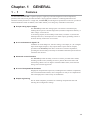
The DIGITRONIK SDC40B is a general-purpose, single-loop controller designed to control temperatures,
pressures, flow rates, levels, pH values and other varying physical conditions. Combining PID control and
numerous auxiliary functions in a single unit, the SDC40B provides high cost-performance control for your device
and instrumentation needs. In addition, a PC loader enables you to design any combination of functions.
● Unique analog input / output
The SDC40B provides three analog inputs. One of these is full multi-input,
enabling direct input of a thermocouple, RTD (resistance temperature detector), or
other voltage / current device.
As for analog outputs, the 5G model provides three (4 to 20mA ×3) and the 2G
model provides two (a 2G output and a 4 to 20mA output), permitting a motor to
be driven directly without use of a converter.
● A rich endowment of digital I / O
In addition to mode changeover, selection setting, event output, etc., the 12 digital
inputs and 8 digital outputs (3 relay outputs and five open collector outputs)
provided on the SDC40B permit direct connection to internal computations,
providing the user the ability to flexibly accommodate automated systems that use
controllers such as PLCs.
● Advanced control functions
The SDC40B provides the ability to select one of four provided control modes,
including cascade control, enabling the user to perform advanced control with
smart-tuning effective for two degrees of freedom PID control, neural network
tuning, and overshoot suppression.
● A host of Computational functions
Roughly 80 computational expressions, including the four arithmetic computation,
selectors and linearization tables, can be assigned to as many as 50 computational
units and employed in a wide variety of combinations.
● Simple engineering
The PC loader simplifies procedures for combining computational units and
selecting other configuration settings.
1-1
Chapter 1. GENERAL
1 - 2
CPL Communications Network based Configuration
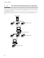
Models equipped with the optional RS-485 communications interface can be connected as a slaved DIGITRONIK's
controller to a CPL communications(Controller Peripheral Link:Yamatake host communication protocol) network.
In this case, the user can employ as the master station the Yamatake's MA500 FA (Factory Automation) Controller
or the MX200 Super Controller.
Models equipped with the optional RS-232C communications interface can be configured in a point-to-point CPL
communications network with a personal computer serving as the master station and the SDC40B as the slave
station.
MA500 or MX200
RS-485
SDC40B(slave station)
Personal computer
RS-232C
RS-232C/RS-485 converter
RS-485
SDC40B(slave station)
Personal computer
RS-232C
SDC40B(slave station)
1-2
Chapter 1. GENERAL
1 - 3
Model Number
Control Func- Power Options
Basic
model No. output tion supply
1
C40B
2G
5G
Options
2
Specifications
Additional
processing
Digital indicating controller
Position proportional output
Current output
Input1: Thermocouples, RTDs, DC current, DC voltage of multi-range
4
Input2: 4 to 20mA DC, 1 to 5V DC
Input3: 1 to 5V DC
AC power supply(90 to 264V AC :Free power supply)
AS
DS
DC power supply(21.6 to 26.4V DC)
1 auxiliary output, 12 digital inputs,
8 digital outputs (3 relays, 5 open collectors)
2 auxiliary outputs, 12 digital inputs,
06*
09*
8 digital outputs (3 relays, 5 open collectors)
No communications interface
RS-485 communication
RS-232C communication
1
2
3
00
T0
K0
D0
B0
L0
Y0
Additional processing not provided
Tropical treatment
Antisulfide treatment
Inspection Certificate provided
Tropical treatment+Inspection Certificate provided
Antisulfide treatment+Inspection Certificate provided
Complying with the traceability certification
*An option 06 can specify only at the time of control output 2G.
An option 09 can specify only at the time of control output 5G.
1-3
Chapter 1. GENERAL
1 - 4
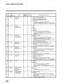
Input Types and Range Numbers
■ Input 1
● Thermocouple
Input type
Range number Code
°C range
°F range
K (CA)
0
K09
0.0
to
1200.0
0
to
2400
K (CA)
1
K08
0.0
to
800.0
0
to
1600
K (CA)
2
K04
0.0
to
400.0
0
to
750
K (CA)
3
K29
-200.0
to
+1200.0
-300
to
+2400
K (CA)
4
K44
-200.0
to
+300.0
-300
to
+700
K (CA)
5
K46
-200.0
to
+200.0
-300
to
+400
E (RC)
6
E08
0.0
to
800.0
0
to
1800
J (IC)
7
J08
0.0
to
800.0
0
to
1600
T (CC)
8
T44
-200.0
to
+300.0
-300
to
+700
B (PR30-6)
9
B18
0.0
to
1800.0
0
to
3300
R (PR13)
10
R16
0.0
to
1600.0
0
to
3100
S (PR10)
11
S16
0.0
to
1600.0
0
to
3100
W (WRe5-26)
12
W23
0.0
to
2300.0
0
to
4200
W (WRe5-26)
13
W14
0.0
to
1400.0
0
to
2552
PR40-20
14
D19
0.0
to
1900.0
0
to
3400
Ni-Ni•Mo
15
Z13
0.0
to
1300.0
32
to
2372
N
16
U13
0.0
to
1300.0
32
to
2372
PL II
17
Y13
0.0
to
1300.0
32
to
2372
DIN U
18
Z08
-200.0
to
+400.0
-300
to
+750
DIN L
19
Z07
-200.0
to
+800.0
-300
to
+1600
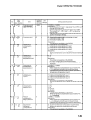
● Resistance temperature detector (RTD)
Input type
F50
°C range
-200.0
to +500.0
°F range
JIS'89 Pt100
32
(IEC Pt 100Ω)
33
F46
-200.0
to +200.0
-300.0 to +400.0
34
F32
-100.0
to +150.0
-150.0 to +300.0
35
F36
-50.0
to +200.0
-50.0 to +400.0
36
F38
-60.00 to +300.0
-76.00 to +104.00
37
F33
-40.00 to
-40.00 to +140.00
38
F05
0.0
to
500.0
0.0 to
900.0
39
F03
0.0
to
300.0
0.0 to
500.0
0.00 to
200.00
JIS'89 J Pt100
1-4
Range number Code
0.00 to
+40.00
100.00
-300.0 to +900.0
40
F01
48
P50
-200.0
to +500.0
-300.0 to +900.0
49
P46
-200.0
to +200.0
-300.0 to +400.0
50
P32
-100.0
to +150.0
-150.0 to +300.0
51
P36
-50.0
to +200.0
52
P38
-60.00 to
+40.00
-76.0 to +104.00
53
P33
-40.00 to
+60.00
-40.00 to +140.00
54
P05
0.0
to
55
P03
0.0
to
56
P01
0.00 to
500.0
-50.0 to +400.0
0.0 to
900.0
300.0
0.0 to
500.0
100.00
0.00 to
200.00
Chapter 1. GENERAL
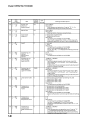
● DC current/voltage
Input type
■ Input 2
4 to 20mA
64
0 to 20mA
65
C08
0 to 10mV
66
M01
10 to +10mV
67
L02
0 to 100mV
68
L01
C01
0 to 1V
69
L04
-1 to +1V
70
L08
1 to 5V
71
V01
0 to 5V
72
L05
0 to 10V
73
L07
-19999 to +26000
DC current/voltage
Input type
■ Input 3
Range number Code Range (program mable)
Range number Code Range (program mable)
4 to 20mA
0
C01
1 to 5V
1
V01
-19999 to +26000
DC voltage
Input type
1 to 5V
Code
V01
Range (program mable)
-19999 to +26000
Handling Precautions
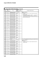
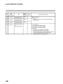
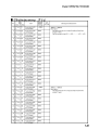
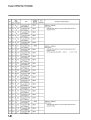
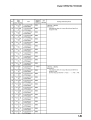
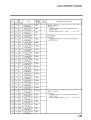
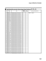
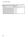
• To set an input range type (SEtup C 10, C 14), enter the range number
from the 4 tables above. Do not enter a number other than the range
numbers listed in the tables.
1-5
Chapter 9.
9 - 1
Analog input 1
(AIR 1)
SPECIFICATIONS
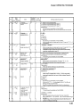
Specifications
Item
Specification
Input types
The following multirange: (See page 9-8)
Thermocouple: K, E, J, T, B, R, S(JIS C 1602-1981)
WRe5-26(Hoskins documents)
PR40-20(Johnson Matthey documents)
Ni-Ni•Mo(General Electric documents)
N(N.B.S.Monograph 161)
PLII(Engelhard Industries documents (IPTS68))
DIN U, DIN L(DIN 43710-1985)
Golden iron chromel(Hayashi Denko documents)
RTD:
Pt100, JPt100(JIS C 1604-1989)
DC current:
4 to 20mA, 0 to 20mA
DC voltage:
0 to 10mV, -10 to +10mV, 0 to 100mV, 0 to 1V,
-1 to +1V, 1 to 5V, 0 to 5V, 0 to 10V
±0.1%FS±1U(This may be affected by indication value conversion and ranges
understand conditions)
0.1 to 0.5s (depends on computation cycle)
Thermocouple and DC voltage input:
Max.±1.3µA (peak value under standard conditions)
The range above 1V is max. -3µA
DC current input: 50Ω±10% (under operating conditions)
RTD: 1.04mA±0.02mA: Current input on terminal A
Thermocouple, DC current and DC voltage:
Variation in indicating value due to input conversion when wiring resistance at
both ends is 250
• 0 to 10mV, -10 to +10mV: 35µV max.
• 0 to 100mV: 60µV max.
• Others: 750µV max.
RTD: ±0.01% FS/Ωmax. in a wiring resistance range of 0 to 10Ω.
±0.02% FS/Ωmax. in a range with a minimum resolution of 0.01°C.
The allowable wiring resistance is 85max. (A zener barrier is available
only for 0.1°C resolution range and requires on-site adjustment.)
Allowable parallel resistance for thermocouple break detection is 1MΩmin.
Thermocouple and DC voltage input: -5 to +15V
DC current input: 28mA
Internal upscale and downscale selection
110% FS or more: upscaled
-10% FS or less:
downscaled
(However, inputs in the -200.0 to +500.0°C range of JIS
Pt100 and the -200.0 to +500.0°C range of JIS JPt100 are
not downscaled. The indicating values lower limit for B
input (0.0 to 1800.0°C) is 20°C.)
±0.5°C (under standard conditions)
Input indicating accuracy
Input sampling cycle
Input bias current
Input impedance
Measuring current
Effect of wiring resistance
Allowable parallel resistance
Maximum allowable input
Burnout
Over range detection
threshold
Cold junction compensation
accuracy
Influence of surrounding
temperature on cold junction
compensation
Cold junction compensation
method
Scaling
Analog input 2
(AIR 2)
Type of inputs
Input indicating accuracy
Input sampling cycle
Input bias current
Input impedance
Maximum allowable input
Burnout
Over range detection
threshold
Scaling
Analog input 3
(AIR 3)
Type of inputs
Input indicating accuracy
Input sampling cycle
Input bias current
Input impedance
±0.2°C(at 0 to 50°C range)
Internal or external compensation (at 0°C) selectable
-19999 to + 26000U(These settings available for linear inputs only. Reverse scaling
and decimal point repositioning can be performed with resolutions to 1/20000.)
4 to 20mAdc, 1 to 5Vdc. See page 9-9.
±0.1% FS ±1U (display value conversion under standard conditions)
0.1 to 0.5s (depends on computation cycle)
1 to 5Vdc input:
±10µAmax. (under operating conditions)
1 to 5Vdc input:
1MΩmin. (under operating conditions)
4 to 20mAdc input: 50Ω±10% (under operating conditions)
1 to 5Vdc input:
0 to 6V
4 to 20mAdc input: 28mA
Downscale
110% FS or more: upscaled
-10% FS or less: downscaled
-19999 to + 26000U (Reverse scaling and decimal point repositioning can be
performed with resolutions to 1/20000.)
1 to 5Vdc. See page 9-9.
±0.1% FS ±1U (display value conversion under standard conditions)
0.1 to 0.5s (depends on computation cycle)
±10µA max. (under operating conditions)
1MΩmin. (under operating conditions)
9-1
Specifications are subject to change without notice.
(08)
Advanced Automation Company
1-12-2 Kawana, Fujisawa
Kanagawa 251-8522 Japan
URL: http://www.azbil.com
1st Edition: Issued in June 1995 (W)
19th Edition: Issued in June 2008 (M)