1
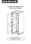
Cadenza Instruction Manual
Cadenza 61
Cadenza 75
We’ll Make It Stress-Free
If you have any questions along the way, just give us a call.
1-800-359-5520. We’re ready to help!
IMPORTANT SAFETY INSTRUCTIONS – SAVE THESE INSTRUCTIONS – PLEASE READ ENTIRE MANUAL PRIOR TO USE
Weight Limits
5 lbs
2.3 kg
5 lbs
2.3 kg
FRONT VIEW
50 lbs
22.7 kg
150 lbs
68.0 kg
30 lbs
13.6 kg
BACK VIEW
50 lbs
22.7 kg
10 lbs
4.5 kg
20 lbs
9.1 kg
10 lbs
4.5 kg
20 lbs
9.1 kg
Cautions and Care
CARE INSTRUCTIONS
For wood with a natural finish, dust regularly with a soft dry cloth. When needed, wipe with a clean, damp, cloth and wipe dry.
CAUTION: Avoid potential personal injuries and property damage!
Serious or fatal crushing injuries can occur from furniture failure. To prevent failure:
● This product is designed for use with flat panel TVs ONLY.
● Do not exceed rated weight limits.
● Place heaviest items in the lowest shelves.
● Never allow children to climb or hang on shelves or doors.
● Always unload furniture before moving.
● Use of anti-tip restraints may only reduce, but not eliminate, the risk of failure.
● Do not use this product for any purpose not explicitly specified by manufacturer.
● If you do not understand these instructions, or have doubts about the safety of the installation, assembly or use of this product,
contact Customer Service or call a qualified contractor.
●
●
Manufacturer is not responsible for damage or injury caused by incorrect assembly or use.
To prevent tipping, be sure to center your flat panel TV (NO CRTs) on the top of your furniture.
2
Required Tools
Supplied Parts and Hardware
WARNING: This product contains small items that could be a choking hazard if swallowed.
Before starting assembly, verify all parts are included and undamaged. If any parts are missing or damaged, do not return the damaged
item to your dealer; contact Customer Service. Never use damaged parts!
*
WARNING: This product contains a magnet. If an implanted medical device such as a pacemaker or implantable cardioverter
defibrillator (ICD) is in use, magnetic fields may affect the operation of those devices, resulting in serious injury or death. If you have an
implanted medical device, keep at least 13 cm (5 in.) between your device and the magnet. Please consult with your physician or medical
professional prior to using this product.
CAUTION: Avoid potential personal injuries and property damage!
●
●
●
●
Tempered glass has been chosen for this product because of its strength and safety characteristics. However, tempered glass should
still be handled with care to avoid possible property damage or personal injury.
Mishandling during shipping, assembly, or use may result in damage that can weaken the tempered glass.
Periodically check the glass to look for chips, cracks, or deep scratches.
If chips, cracks, or deep scratches are found, discontinue use and contact customer service.
*
Center Foot
03 x1
End Foot
02 x2
End Cap
04 x4
Cabinet
01 x1
Top Glass Panel
Screen Panel
05 x1
07 x2
Glass Shelf
06 x1
End Foot Screw
Center Foot Screw
08 x8
09 x2
3
Dimensions
61.0
1549
20.1
511
Cadenza 61
19.2
487
in.
[mm]
B
A
8.1
205
24.9
632
22.4
569
19.4
493
21.2
539
(11U)
B
A
14.5
368
4.5
115
8.1
206
7.5
191
21.8
554
19.0
482
23.0
584
8.4
213
18.0
457
11.3
287
3.0
76
A A
75.0
1905
34.1
867
Cadenza 75
19.2
487
in.
[mm]
19.4
493
B B
B
A
8.1
205
24.9
632
22.4
569
21.2
539
(11U)
B
A
14.5
368
4.5
115
8.1
206
7.5
191
19.0
482
21.8
554
8.4
213
11.3
287
18.0
457
3.0
76
A A
B B
4
23.0
584
1 Feet
Parts and Hardware for STEP 1
End Foot
Center Foot
End Cap
02 x2
03 x1
04 x4
Cabinet
End Foot Screw
01 x1
08 x8
Center Foot Screw
09 x2
Carefully lift the cabinet 01 and lay it on its back onto a protective surface.
Slide the end feet 02 into the square tubing and secure using eight end foot screws 08 .
Press the end caps 04 into the end feet 02 .
Install the center foot 03 using two center foot screws 09 .
Carefully lift and set the cabinet 01 upright on its feet.
08
08
01
03 09
02
02
04
For cabinet install to sit closer to the floor:
OPT
02
Press the end caps 04 into the square tubing on the cabinet 01 .
Do not use the end feet 02 , center foot 03 or screws 08 and 09 .
01
04
5
04
2 Soundbar Preparation (optional)
To make room for a soundbar or other long equipment:
OPT
Remove the dividers on one or both sides of cabinet 01 .
Remove the support pins from cabinet 01 .
NOTE: See STEP 5 on PAGE 9 to switch the front door panels with mesh screens
to accommodate the speakers.
Support Pin
Divider
01
6
Soundbar
3 Glass Panels
Parts for STEP 3
Top Glass Panel
Glass Shelf
05 x1
06 x1
Set the glass shelf 06 into place so the recessed holes in the glass
line up with the glass supports.
Set the top glass panel 05 into place so the recessed holes in the glass
line up with the glass supports.
Recessed Hole
Glass Support
05
06
05
06
01
7
4 Shelf Adjustment
Remove the door and rail cover by removing the three
mounting screws on each side of the cabinet 01 .
Mounting
Screw
01
Rail Cover
Door
Remove the four rack screws holding the shelf in place.
Reposition the shelf and secure with the four rack screws.
Rack
Screw
Reattach the door and rail cover using the mounting six screws.
Shelf
01
Door
Rail Cover
8
5 Door Screens (optional)
Parts for STEP 5
Screen Panel
07 x2
To utilize speakers behind the doors, inside the cabinet:
OPT
a.
Pull the 4 retaining strips from the back of the door frame.
b.
Remove the solid panel.
c.
Install the screen panel 07 into the door.
d.
Replace the 4 retaining strips to secure the screen in place.
01
a
Retaining Strip
07
b
c
Solid Panel
9
07
d
Retaining
Strip
6 Operation
REMOVING THE BACK PANELS
Remove the magnetic back panels of cabinet 01 by pulling away from the cabinet.
Replace by lining up the panels and allowing the magnets to catch the cabinet 01 .
01
CABINET DOORS AND DRAWERS
The doors and drawers include an automatic
closing mechanism.
Simply close the doors or drawers until you
feel the auto close feature take affect, then
release and allow the door or drawer to finish
closing on its own.
Latch
Removal:
01
Doors - See STEP 4 on PAGE 8
Drawers - Pull outward on the latches on
the underside of the drawer while pulling the
drawer out and off the drawer rails.
Drawer
Door
NOTE: Hold the latches outward while
installing the drawers.
10
7 ELM701 Anti-tip Strap (Sold Separately)
OPT
11
Thank you for choosing Sanus! Please take a moment to let us know how we did:
Call us: 800-359-5520
Email us: [email protected]
Leave a review: sanus.com
Find us on Facebook: SANUS
Follow us on Twitter @sanussystems
Milestone AV Technologies and its affiliated corporations and subsidiaries (collectively, “Milestone”), intend to make this manual accurate and complete. However,
Milestone makes no claim that the information contained herein covers all details, conditions, or variations. Nor does it provide for every possible contingency
in connection with the installation or use of this product. The information contained in this document is subject to change without notice or obligation of any
kind. Milestone makes no representation of warranty, expressed or implied, regarding the information contained herein. Milestone assumes no responsibility for
accuracy, completeness or sufficiency of the information contained in this document.
©2013 Milestone AV Technologies, a Duchossois Group Company. All rights reserved. Sanus is a division of Milestone.
All other brand names or marks are used for identification purposes and are trademarks of their respective owners.
SANUS • 6436 City West Parkway • Eden Prairie, MN 55344 USA
6901-002271 00
12