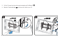
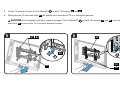
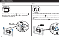
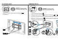
1
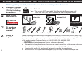
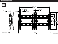
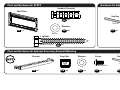
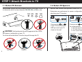
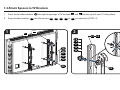
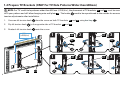
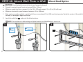
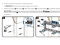
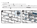
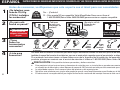
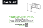
LT25 INSTRUCTION MANUAL
We’ll Make It Stress-Free
If you have any questions along the way, just give us a call.
1-800-359-5520. We’re ready to help!
Scan for easy install video
http://san.us/630
IMPORTANT SAFETY INSTRUCTIONS – SAVE THESE INSTRUCTIONS – PLEASE READ ENTIRE MANUAL PRIOR TO USE
Before getting started, let’s make sure this mount is perfect for you!
1
2
Does your TV weigh
more than 175 lb
(79.4 kg) including
accessories?
175 lb
(79.4 kg)
What is your
wall made of?
No — Perfect!
Yes — This mount is NOT compatible. Visit MountFinder.Sanus.com or call
1-800-359-5520 (UK: 0800-056-2853) to find a compatible mount.
Drywall with
wood studs?
Solid concrete or
concrete block?
Unsure?
CAUTION:
DO NOT install
into drywall alone
3
Perfect!
Do you have
all the tools
needed?
Stud Finder Awl
4
Ready to
begin?
Call Customer Service:
1-800-359-5520 (UK: 0800-056-2853)
Perfect!
Pencil
Level Screwdriver Tape Measure
3/16 in.
(5 mm)
Wood
Drill Bit
1/2 in.
(13 mm)
Concrete
Drill Bit Electric Drill
Hammer
1/2 in.
(13 mm)
Socket Wrench
Please read through these instructions completely to be sure you’re comfortable with this easy install process.
Also check your TV owner’s manual to see if there are any special requirements for mounting your TV.
If you do not understand these instructions or have doubts about the safety of the installation, assembly or use
of this product, contact Customer Service at 1-800-359-5520 (UK: 0800-056-2853).
CAUTION: Avoid potential personal injuries and property damage!
●
2
●
●
●
This product includes directions and hardware for use with wood stud, solid concrete and concrete block walls –
DO NOT install into drywall alone.
The wall must be capable of supporting five times the weight of the TV and mount combined.
Do not use this product for any purpose not explicitly specified by manufacturer.
Manufacturer is not responsible for damage or injury caused by incorrect assembly or use.
Dimensions
in.
[mm]
27.541 MAX.
699.53
3.098
78.69
2.000
50.80
8°
MAX TILT UP
0.506
12.86
1.503 MIN.
38.18
2.000
50.80
12.166
309.02
8.635
219.34
17.323
440.00
18.220
462.79
10°
MAX TILT DOWN
30.006
762.16
NOTE:
MAX. HEIGHT ADJUST
.5 IN.
3
Parts and Hardware
WARNING: This product contains small items that could be a choking hazard if swallowed. Before starting assembly, verify all parts
are included and undamaged. If any parts are missing or damaged, do not return the damaged item to your dealer; contact Customer Service.
Never use damaged parts!
NOTE: Not all hardware included will be used.
Parts and Hardware for STEP 1
TV Screws
TV Brackets
01
x1
02
M4 x 20mm
03 x4
M4 x 30mm
07 x4
M4 x 40mm
11 x4
M5 x 20mm
04 x4
M5 x 30mm
08 x4
M5 x 40mm
12 x4
M6 x 25mm
05 x4
M6 x 40mm
09 x4
M6 x 55mm
13 x4
M8 x 25mm
06 x4
M8 x 45mm
10 x4
M8 x 60mm
14 x4
x1
Spacers
Washers
M4 / M5
4
4mm
7mm
15
16
x4
x4
14mm
24mm
38mm
17
18
19
x4
x4
x4
20
x4
21
x4
M6 / M8
22
x4
Parts and Hardware for STEP 2
Hardware for Adjustments
Anchors (Concrete)
Wall Plate
Hex Key
24
x6
3/16 in.
Washers
23
25
x1
27
x6
x1
5/16 in.
Lag Bolts
5/16 x 2 1/2 in.
26
x6
Parts and Hardware for Optional Accessory Bracket Mounting
Bracket
Cage Nut
Washers
Screw
10-32 x 3/8 in.
Hex Key
1/8 in.
10-32
28
x2
29
x4
30
x4
31
x4
32
x1
5
STEP 1 Attach Brackets to TV
1-1 Select TV Screws
1-2 Select TV Spacers
Hand thread screws into the threaded inserts on the back of your TV
to determine which screw diameter (M4, M5, M6, or M8) to use.
Spacers and screws are supplied to install your TV bracket.
M4 M5
M6
M8
Determine your preference for spacer configuration when
attaching your TV bracket.
a
CAUTION: Verify adequate thread engagment of the screw
and spacer combination on your TV.
Too Short
Correct
Use spacers 15 or 16
if your TV has a flat back
AND you want your TV
closer to the wall.
Flat Back
Too short will not hold the TV and too long will damage the TV.
6
15 16
Too Long
b
17 18 19
Use spacers 17 , 18 or 19
to accommodate:
● Round/irregular back TVs
● TVs with inset mounting holes
● Extra space needed for cables
Round Back
Inset Holes
Cables
1-3 Attach Spacers to TV Brackets
1.
Press the shoulder washers 20 through the openings of TV brackets 01 and 02 that line up with your TV hole pattern.
2.
Snap shoulder washers 20 into the spacers 15 , 16 , 17 , 18 or 19 you selected in STEP 1-2.
1
01
2
02
01 02
15
16
17
18
19
20
15
16
17
18
19
20
7
1-4 Prepare TV Brackets (ONLY For TV Hole Patterns Wider than 600mm)
NOTE: For TV's with hole patterns wider than 600 mm (≈23 5/8 in.), the placement of TV brackets 01 and 02 must be reversed on your TV
to fit your pattern and still allow hanging onto wall plate 23 . The knobs K need to be repositioned to the outside for accessability and tilt
tension adjustments after installation.
1.
Unscrew tilt tension knob K from the screw on both TV brackets 01 and 02 using hex key 27 .
2.
Flip tilt tension knob K to the opposite side of TV bracket 01 and 02 .
3.
Reattach tilt tension knob K onto the screw.
1
> 600mm
(≈23 5/8 in.)
02
2
02
27
K
1
01
8
01
K
02
27
K
2
K
01
27
02
3
3
01
27
K
K
1-5 Attach TV Brackets
Center the TV brackets 01 and 02 over your TV hole pattern as shown, making sure the brackets are level with each other.
IMPORTANT: Install with tilt tension knobs
K toward the outside.
Install using the screw and washer combination [a] or [b] you selected for your TV.
NOTE: Use washer 21 for screws 03 , 04 , 07 , 08 , 11 and 12 .
a
Flat Back
03 04 05 06
Use washer 22 for screws 05 , 06 , 09 , 10 , 13 and 14 .
01 02
K
21 22
15 16
b
Round Back / Extra Space
07 08 09 10 11 12 13 14
K
17 18 19
21 22
9
STEP 2A Attach Wall Plate to Wall Wood Stud Option
CAUTION: Avoid potential personal injuries and property damage!
●
●
●
Drywall covering the wall must not exceed 5/8 in. (16 mm)
Minimum wood stud size: common 2 x 4 in. (51 x 102 mm) nominal 1½ x 3½ in. (38 x 89 mm)
Minimum horizontal space between fasteners: 16 in. (406 mm)
1.
Stud centers must be verified – not all walls have conventional 16 in. (406 mm) stud spacing. Verify the center of the stud(s) using an awl, a
thin nail, or an edge to edge stud finder.
2.
Level the wall plate 23 and mark the hole locations.
NOTE: For assistance in determining wall plate location, see HeightFinder at sanus.com.
2
1
Max.
5/8 in.
(16 mm)
10
Min. 16 in.
(406 mm)
23
3.
Drill the four pilot holes using a 3/16 in. (5 mm) diameter drill bit.
IMPORTANT: Pilot holes must be drilled to a depth of 2 ½ in. (63 mm).
4.
Install the four washers 25 and lag bolts 26 . Tighten all four lag bolts 26 only until the washers 25 are pulled firmly against the wall plate 23 .
CAUTION: Avoid potential personal injury or property damage! All four lag bolts 26 MUST BE firmly tightened to prevent unwanted
movement of the wall plate 23 . Ensure the wall plate is securely fastened to the wall before continuing on to the next step.
Go to PAGE 14.
3
2½ in.
(63 mm)
4
25
26
3/16 in.
(5 mm)
23
11
STEP 2B Attach Wall Plate to Wall Solid Concrete or Concrete Block Option
CAUTION: Avoid potential personal injuries and property damage!
●
●
●
●
Mount the wall plate 23 directly onto the concrete surface
Minimum solid concrete thickness: 8 in. (203 mm)
Minimum concrete block size: 8 x 8 x 16 in. (203 x 203 x 406 mm)
Minimum horizontal space between fasteners: 8 in. (203 mm)
1.
Position the wall plate 23 on the wall at your desired height. Level the wall plate and mark the six hole locations.
NOTE: For assistance in determining wall plate location, see Height Finder at sanus.com.
2.
Drill six pilot holes using a 1/2 in. (13 mm) diameter drill bit.
IMPORTANT: Pilot holes must be drilled to a depth of 3 in. (75 mm). Never drill into the mortar between blocks.
1
2
23
3 in. (75 mm)
1/2 in.
(13 mm)
Min.
8 in.
(203 mm)
12
Insert six anchors 24 .
3.
CAUTION: Be sure the anchors
24 are seated flush with the concrete surface.
Install the six washers 25 and lag bolts 26 . Tighten all six lag bolts 26 only until the washers 25 are pulled firmly against the wall plate 23 .
4.
CAUTION: Avoid potential personal injury or property damage! All four lag bolts 26 MUST BE firmly tightened to prevent unwanted
movement of the wall plate 23 . Ensure the wall plate is securely fastened to the wall before continuing on to the next step.
4
3
25
23
26
24
13
OPTIONAL ClickFit ™ Accessory Bracket Mounting
NOTE: If not installing this option, Skip to STEP 3 on PAGE 16.
CAUTION: The ClickFit™ Surge Protector Mounting Accessory supports a maximum weight of 3 lb (1.3 kg).
Cage Nut Assembly Option
1.
Pinch the ends of cage nuts 29 and insert into brackets 28 , then press brackets 28 into the channels on wall plate 23 .
2.
Secure your accessory onto brackets 28 with with washers 30 and screws 31 using hex key 32 .
1
28
14
23
29
2
23
32
31
28
30
Screw Assembly Option
1.
Secure brackets 28 onto your accessory with washers 30 and screws 31 using hex key 32 .
2.
Press brackets 28 into the channels on wall plate 23 .
1
28
2
30
31
32
23
28
15
STEP 3 Attach TV to Wall Plate
HEAVY! You may need assistance with this step.
1.
Hang the TV onto wall plate 23 by hooking the tops of TV brackets 01 and 02 .
2.
Gently rest the TV onto wall plate 23 . An audible click ensures the TV is in the locked position.
CAUTION: Avoid potential injuries or property damage! The ClickStand™
C on both TV brackets 01 and 02 , must be locked onto
wall plate 23 to ensure the TV is securely fastened in place.
1
01 02
01 02
2
01 02
23
23
C
23
16
23
Manage Cables
1.
Tighten the tilt adjustment knobs K with hex key 27 .
CAUTION: Avoid potential injuries or property damage! Tilt adjustment knobs
2.
K must be tight when the TV is in the wiring position.
Release the ClickStand™ C on both TV brackets 01 and 02 .
1
2
01 02
K
01 02
23
C
27
23
23
17
3.
Pull the TV away from the wall enough to extend each ClickStand™ C .
4.
Rest the TV onto wall plate 23 and connect all cables to your TV.
3
4
01 02
23
C
01 02
C
23
23
18
5.
Lift the TV enough to lower the ClickStand™ C on both TV brackets 01 and 02 .
6.
Gently rest the TV onto wall plate 23 . An audible click ensures the TV is in the locked position.
CAUTION: Avoid potential injuries or property damage! The ClickStand™
C on both TV brackets 01 and 02 , must be locked onto
wall plate 23 to ensure the TV is securely fastened in place.
5
6
01 02
23
23
23
C
23
C
01
02
19
Adjustments
LEVEL
TILT
To level your TV, use hex key 27 to turn the level screw L
on the top of either TV bracket 01 or 02 to raise or lower
that respective side of the TV.
Your TV should adjust easily when moved, then stay in place.
Adjust the tilt tension knobs K if your TV naturally tilts up or down.
NOTE: If you do not intend to adjust the tilt for different viewing locations,
you can tighten the tilt tension knobs K to prevent unwanted movement.
27
01 02
L
01 02
K
27
20
TV LATERAL SHIFT
REMOVING THE TV
HEAVY! You may need
assistance with this step.
Slide the TV left or right along the wall plate 23
to reposition.
HEAVY! You may need
assistance with this step.
1.
Tighten tilt tension knobs K .
2.
Release the ClickStand™ C on both TV brackets 01 and 02 .
3.
Pull the TV away from the wall and extend each ClickStand™ C .
4.
Rest the TV onto wall plate 23 and disconnect all cables from the TV.
5.
Lift the TV from the wall plate 23 .
5
K
23
1
27
23
01
2
3
4
23
02
01 02
C
C
21
ESPAÑOL
1
2
INSTRUCCIONES DE SEGURIDAD IMPORTANTES: CONSÉRVELAS Y LEA TODO EL MANUAL ANTES DE UTILIZAR ESTE PRODUCTO
Antes de comenzar, verifiquemos que este soporte sea el ideal para sus necesidades.
¿Su televisor pesa
más de 79,4 kg
(175 lb), incluidos
los accesorios?
79,4 kg
(175 lb)
¿De qué está
hecha su pared?
¿Tabiques
de yeso con
montantes de
madera?
PRECAUCIÓN:
NO lo instale en
tabiques únicamente
de yeso
3
4
No — ¡Perfecto!
Sí — Este soporte NO es compatible. Visite MountFinder.Sanus.com o llame al
1-800-359-5520 (Reino Unido: 0800-056-2853) para encontrar un soporte compatible.
¡Perfecto!
¿Hormigón sólido
o bloques de
cemento?
Localizador Punzón
de montantes
¿Listo para
comenzar?
Llame al 1-800-359-5520
(Reino Unido: 0800-056-2853)
¡Perfecto!
¿Tiene
todas las
herramientas
necesarias?
Lápiz
Nivel
Destornillador Cinta métrica
¿No está
seguro?
5 mm
(3/16'')
Madera
Broca
13 mm
(1/2'')
Hormigón
Broca
13 mm
(1/2”)
Taladro eléctrico
Martillo
Llave de tubo
Lea estas instrucciones en su totalidad para estar seguro de sentirse cómodo con este fácil proceso de instalación. Consulte
también el manual del usuario de su televisor para ver si existe algún requisito especial para instalar su televisor en la pared.
Si no entiende las instrucciones o si tiene dudas acerca de la seguridad de la instalación, del ensamblado o del uso del
producto, póngase en contacto con el servicio de atención al cliente al 1-800-359-5520 (Reino Unido: 0800-056-2853).
PRECAUCIÓN: Evite posibles lesiones personales y daños materiales.
●
22
●
●
●
Este producto incluye instrucciones y elementos de sujeción para su instalación en paredes con montantes de madera,
en superficies de hormigón y sobre bloques de cemento. NO lo instale en tabiques únicamente de yeso.
La pared debe soportar cinco veces el peso del televisor y del soporte juntos.
No utilice este producto para ningún otro propósito que no sea el explícitamente especificado por el fabricante.
El fabricante no se responsabiliza por ningún daño o lesión resultante del montaje incorrecto o de uso indebido.
ESPAÑOL
Piezas y elementos de sujeción
Ver PÁGINA 4
ADVERTENCIA: Este producto contiene piezas pequeñas que, si fuesen tragadas, podrían producir asfixia. Antes de iniciar el ensamblaje,
compruebe que todas las piezas estén incluidas y en buenas condiciones. Si faltan piezas o alguna está dañada, no devuelva el artículo al distribuidor.
Póngase en contacto con el servicio de atención al cliente. Nunca utilice piezas deterioradas.
NOTA: No todos los elementos de sujeción incluidos deberán utilizarse.
PASO 1 Colocar la placa de sujeción en el televisor
Ver PÁGINA 6
1-1 Seleccione los tornillos del televisor
Enrosque manualmente los tornillos en los encastres roscados del dorso del televisor a fin de determinar qué diámetro de tornillos (M4, M5, M6 o M8) debe utilizar.
PRECAUCIÓN: Verifique que el tornillo o la combinación de tornillo y espaciador enrosquen correctamente.
Si el tornillo es demasiado corto, no sostendrá el televisor. Si es demasiado largo, el aparato se dañará.
1-2 Seleccione los espaciadores del televisor
Se incluyen espaciadores y tornillos para instalar el soporte de su televisor. Defina su preferencia para la configuración del espaciador cuando fije el soporte de
su televisor.
Utilice los espaciadores 15 o 16 si el dorso de su televisor es plano Y quiere que su televisor esté más cerca de la pared.
Utilice los espaciadores 17 18 o 19 para acomodar: televisores con dorso redondeado o irregular, televisores con orificios de montaje intercalados y en
caso de necesitar un espacio adicional para cables.
1-3 Coloque los espaciadores en las placas de sujeción del televisor
1.
2.
Pase las arandelas con reborde 20 por los orificios de las placas de sujeción del televisor 01 y 02 asegúrese de que se alinea con el
patrón de orificios del televisor.
Fije las arandelas con reborde 20 a los espaciadores 15 , 16 , 17 , 18 o 19 que seleccionó en el PASO 1-2.
1-4 Prepare las placas de sujeción del televisor: SÓLO para patrones de orificios de televisor más anchos de 600mm (23 5/8 pulg.)
NOTA: Para patrones de orificios más anchos de 600 mm (≈23 5/8 pulg.), la colocación de las placas de sujeción del televisor 01 y 02 debe
estar invertida en el televisor para encajar con el patrón y poder colgarlo en la placa mural 23 . Las perillas K deben recolocarse hacia fuera
para facilitar la accesibilidad y para ajustar la tensión de inclinación después de la instalación.
23
ESPAÑOL
2.
Desatornille la perilla de tensión de inclinación K del tornillo de ambos soportes del televisor 01 y 02 utilice la llave hexagonal 27 .
Gire la perilla de tensión de inclinación K en dirección contraria al soporte del televisor 01 y 02 .
3.
Vuelva a ajustar la perilla de tensión de inclinación K en el tornillo.
1.
1-5 Fijar las placas de sujeción del televisor
Centre los soportes del televisor 01 y 02 sobre el patrón de orificios de su televisor según se muestra, asegurándose de que los soportes están
nivelados entre sí.
IMPORTANTE: Instale con las perillas de tensión de inclinación K hacia fuera.
Instale usando la combinación de tornillo y arandela [a] o [b] que seleccionó para su televisor.
NOTA: Use la arandela 21 para los tornillos 03 , 04 , 07 , 08 , 11 y 12 .
Use la arandela 22 para los tornillos 05 , 06 , 09 , 10 , 13 y 14 .
PASO 2A Fijar la placa mural a la pared Opción para montantes de madera
Ver PÁGINA 10
PRECAUCIÓN: Evite posibles lesiones personales y daños materiales.
●
●
●
1.
2.
3.
4.
24
El yeso que recubre la pared no debe exceder los 16 mm (5/8'')
Tamaño mínimo del montante de madera: común 51 x 102 mm (2'' x 4") nominal 38 x 89 mm (1½'' x 3½")
Espacio horizontal mínimo entre los elementos de sujeción: 406 mm (16'')
Los montantes centrales deben verificarse: no todas las paredes tienen un espaciado convencional entre montantes de 406 mm (16"). Verifique el centro de
los montantes con un punzón o un clavo delgado o bien utilice un detector de bordes de montantes.
Nivele la placa mural 23 y marque la ubicación de los orificios.
NOTA: Si necesita ayuda para determinar la ubicación de la placa mural, utilice la herramienta HeightFinder disponible en sanus.com.
Haga los cinco orificios guía con una mecha de 5 mm (3/16") de diámetro.
IMPORTANTE: Los orificios guía deben realizarse hasta una profundidad de 63 mm (2½").
Instale las cuatro arandelas 25 y los tornillos tirafondo 26 . Ajuste los tornillos tirafondo 26 solamente hasta que las arandelas 25 queden firmes contra la
placa mural 23 .
PRECAUCIÓN: Evite posibles lesiones personales y daños materiales. Los cuatro tornillos tirafondo 26 DEBEN ESTAR apretados firmemente para evitar que la
placa mural se desplace 23 . Asegúrese de que la placa mural está fijada con seguridad a la pared antes de proceder con el siguiente paso.
Vaya la PÁGINA 14.
ESPAÑOL
PASO 2B Fijar la placa mural a la pared Opción para hormigón sólido o bloques de cemento
PRECAUCIÓN: Evite posibles lesiones personales y daños materiales.
●
●
●
●
1.
Ver PÁGINA 12
Instale la placa mural 23 directamente sobre la superficie de hormigón
Espesor mínimo del hormigón: 203 mm (8'')
Tamaño mínimo del bloque de cemento: 203 x 203 x 406 mm (8'' x 8'' x 16'')
Espacio horizontal mínimo entre los elementos de sujeción: 203 mm (8'')
Coloque la plantilla de la placa mural 23 en la pared a la altura que desee. Nivele la placa mural y marque las ubicaciones de los seis orificios.
NOTA: Si necesita ayuda para determinar la ubicación de la placa mural, utilice la herramienta HeightFinder disponible en sanus.com.
2.
Haga los seis orificios guía con una mecha de 13 mm (1/2") de diámetro.
IMPORTANTE: Los orificios guía deben realizarse hasta una profundidad de 75 mm (3"). Nunca perfore el cemento que une los bloques.
3.
Inserte los seis anclajes para hormigón 24 .
PRECAUCIÓN: Cerciórese de que los anclajes 24 queden nivelados respecto de la superficie de hormigón.
4.
Instale las seis arandelas 25 y los tornillos tirafondo 26 . Ajuste los seis tornillos tirafondo 26 solamente hasta que las arandelas 25 queden firmes
contra la placa mural 23 .
PRECAUCIÓN: Evite posibles lesiones personales y daños materiales. Los cuatro tornillos tirafondo 26 DEBEN ESTAR apretados firmemente para evitar
que la placa mural se desplace 23 . Asegúrese de que la placa mural está fijada con seguridad a la pared antes de proceder con el siguiente paso.
ClickFit OPCIONAL™ Montaje de la placa de sujeción accesoria
Ver PÁGINA 14
NOTA: Si no va a instalar esta opción, prosiga hasta el PASO 3 en la PÁGINA 16.
PRECAUCIÓN: ClickFit™ El accesorio de montaje protector contra sobretensión soporta un peso máximo de 1,3 kg (3 lb).
Opción de ensamblaje con tuerca de jaula
1.
2.
Presione los extremos de las tuercas de jaula 29 e insértelas en los soportes 28 , y después pase éstos últimos 28 por los canales de la placa mural 23 .
Fije el accesorio en los soportes 28 con las arandelas 30 y tornillos 31 usando la llave hexagonal 32 .
Opción de ensamblaje con tornillo
1.
2.
Fije los soportes 28 en el accesorio con las arandelas 30 y tornillos 31 usando la llave hexagonal 32 .
Pase los soportes 28 por los canales de la placa mural 23 .
25
ESPAÑOL
PASO 3 Acoplar el televisor a la placa mural
Ver PÁGINA 16
¡ELEMENTO PESADO! Es posible que necesite ayuda en este paso.
1.
Cuelgue el televisor en la placa mural 23 enganchando la parte superior de los soportes del televisor 01 y 02 .
2.
Apoye suavemente el televisor en la placa mural 23 . Un clic sonoro le informará de que el televisor está en la posición de bloqueo.
PRECAUCIÓN: Evite posibles lesiones personales y daños materiales. El ClickStand™ C en ambos soportes del televisor 01 y 02 ,
debe estar fijado a la placa mural 23 para garantizar que el televisor está asegurado en su sitio.
Organizar los cables
1.
Ver PÁGINA 17
Ajuste las perillas de tensión de inclinación K con la llave hexagonal 27 .
PRECAUCIÓN: Evite posibles lesiones personales y daños materiales. Las perillas de tensión de inclinación K deben estar ajustadas
cuando el televisor está en la posición de cableado.
26
2.
Libere el ClickStand™ C de ambos soportes del televisor 01 y 02 .
3.
Separe el televisor de la pared lo suficiente como para extender cada ClickStand™ C .
4.
Apoye el televisor en la placa mural 23 y conecte todos los cables de su televisor.
5.
Levante el televisor lo suficiente como para bajar el ClickStand™ C de ambos soportes del televisor 01 y 02 .
6.
Apoye suavemente el televisor en la placa mural 23 . Un clic sonoro le informará de que el televisor está en la posición de bloqueo.
PRECAUCIÓN: Evite posibles lesiones personales y daños materiales. El ClickStand™ C en ambos soportes del televisor 01 y 02 ,
debe estar fijado a la placa mural 23 para garantizar que el televisor está asegurado en su sitio.
ESPAÑOL
Ajustes
Ver PÁGINA 18
NIVEL
Para nivelar el televisor, gire el tornillo L de ajuste de nivel que se encuentra en la parte superior de cualquiera de las placas de sujeción 01
or 02 usando la llave hexagonal 27 para subir o bajar el lado correspondiente del televisor.
INCLINACIÓN
El televisor debe acomodarse fácilmente al moverlo y, posteriormente, quedar en su lugar. Si el televisor se inclina hacia arriba o hacia abajo de forma natural,
ajuste las perillas de tensión de inclinación K .
NOTA: Si no pretende ajustar la inclinación a diferentes ubicaciones de visión, puede ajustar las perillas de tensión de inclinación K para evitar movimientos
no deseados.
DESPLAZAMIENTO LATERAL DEL TELEVISOR
¡ELEMENTO PESADO! Es posible que necesite ayuda en este paso.
Deslice el televisor hacia la izquierda o hacia la derecha junto con la placa mural 23 para cambiar su posición.
EXTRACCIÓN DEL TELEVISOR
¡ELEMENTO PESADO! Es posible que necesite ayuda en este paso.
1.
Ajuste las perillas de tensión de inclinación K .
2.
Libere el ClickStand™ C de ambos soportes del televisor 01 y 02 .
3.
Separe el televisor de la pared y extienda cada ClickStand™ C .
4.
Apoye el televisor en la placa mural 23 y desconecte todos los cables del televisor.
5.
Levante el televisor de la placa mural 23 .
27
Thank you for choosing Sanus! Please take a moment to let us know how we did:
Call us: 1-800-359-5520
UK: 0800 056 2853
Email us: [email protected]
Like us on Facebook.com /sanussystems
Leave a review: sanus.com
Follow us on Twitter: @ sanussystems
Milestone AV Technologies and its affiliated corporations and subsidiaries (collectively, “Milestone”), intend to make this manual accurate and complete. However,
Milestone makes no claim that the information contained herein covers all details, conditions, or variations. Nor does it provide for every possible contingency in
connection with the installation or use of this product. The information contained in this document is subject to change without notice or obligation of any kind.
Milestone makes no representation of warranty, expressed or implied, regarding the information contained herein. Milestone assumes no responsibility for accuracy,
completeness or sufficiency of the information contained in this document.
©2014 Milestone AV Technologies. All rights reserved. Sanus is a division of Milestone.
All other brand names or marks are used for identification purposes and are trademarks of their respective owners.
SANUS • 6436 City West Parkway • Eden Prairie, MN 55344 USA
6901-002432 00