1
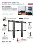
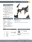
THANK YOU FOR CHOOSING SANUS
THE #1 TV MOUNT BRAND IN THE US.
VST4 Instruction Manual
Scan for easy
install video
SANUS MAGNETIC STUD FINDER
Designed to find your studs and make life easier – included in hardware kit.
magnet
locates screws in drywall
to show exactly where
your studs are
probing pin
helps find the edges of
your stud within the wall
level
attaches to your wall plate
for hands free leveling
TWO SIMPLE STEPS TO FINDING YOUR STUDS:
Step 1
Holding it vertically, lightly move the SANUS
Magnetic Stud Finder up and down while
sliding across your wall. The magnet within
will be attracted to the screws in the stud.
Once the magnet has landed on a screw,
place a pencil mark on the wall
directly below the magnet.
Step 2
Pull apart the SANUS Magnetic Stud Finder to
expose the probing pin within. Starting about
1/2 inch away from the first pencil mark insert
the probing pin into the wall every 1/8 inch until
it inserts completely into the wall. Once that
happens, you know you've found one edge of
your stud. Repeat this process till you have
found the stud edges and center of the stud.
You can verify this is a stud by moving the
Magnetic Stud Finder up or down to find
a second or third screw within the wall.
WARNING:This product contains a magnet. If an implanted medical device such as a pacemaker or implantable cardioverter defibrillator (ICD) is in use, magnetic fields may affect the operation of
those devices, resulting in serious injury or death. If you have an implanted medical device, keep at least 13 cm (5in.) between your device and the magnet. Please consult with your physician or medical
professional prior to using this product.
VST4
We’ll Make It Stress-Free
If you have any questions along the way, just give us a call.
1-800-359-5520 (UK: 0800-056-2853) We’re ready to help!
Lo haremos sin estrés
Si tiene preguntas mientras realiza la instalación, llámenos.
1-800-359-5520 (Reino Unido: 0800-056-2853) Estamos listos para ayudarlo.
3
IMPORTANT SAFETY INSTRUCTIONS – SAVE THESE INSTRUCTIONS – PLEASE READ ENTIRE MANUAL PRIOR TO USE
Before getting started, let’s make sure this mount is perfect for you!
1
2
Does your TV weigh
more than 50 lb
(22.7 kg) including
accessories?
50 lb
(22.7 kg)
What is your
wall made of?
No — Perfect!
Yes — This mount is NOT compatible. Visit MountFinder.Sanus.com or call
1-800-359-5520 (UK: 0800-056-2853) to find a compatible mount.
Drywall with
wood studs?
Perfect!
3
Do you have
all the tools
needed?
Screwdriver Tape Measure
4
Ready to
begin?
Solid concrete or
concrete block?
Call Customer Service:
1-800-359-5520 (UK: 0800-056-2853)
Perfect!
1/8 in.
(3 mm)
Wood
Drill Bit
3/8 in.
(10 mm)
Concrete
Drill Bit
Unsure?
Electric Drill
Hammer
7/16 in.
(12 mm)
Socket Wrench
Pencil
3/8 in.
(10 mm)
Wrench
Please read through these instructions completely to be sure you’re comfortable with this easy install process.
Also check your TV owner’s manual to see if there are any special requirements for mounting your TV.
If you do not understand these instructions or have doubts about the safety of the installation, assembly or use
of this product, contact Customer Service at 1-800-359-5520 (UK: 0800-056-2853).
CAUTION: Avoid potential personal injuries and property damage!
●
4
●
●
●
This product includes directions and hardware for use with wood stud, solid concrete and concrete block walls –
DO NOT install into drywall alone.
The wall must be capable of supporting five times the weight of the TV and mount combined.
Do not use this product for any purpose not explicitly specified by manufacturer.
Manufacturer is not responsible for damage or injury caused by incorrect assembly or use.
STEP 1 Attach Bracket to TV
Parts and Hardware for STEP 1
WARNING: This product contains small items that could be a choking hazard if swallowed.
Before starting assembly, verify all parts are included and undamaged. If any parts are missing or damaged, do not return the damaged
item to your dealer; contact Customer Service. Never use damaged parts!
NOTE: Not all hardware included will be used.
TV Bracket*
200 x 200 Extension
200 x 200 Extension Screw
*You may need to separate the TV
bracket 01 from the wall plate 18
before starting this step.
M6 x 14mm
03 x4
01
200 x 200 Extension Nut
04 x4
18
01
01 x1
02 x2
5
Parts and Hardware for STEP 1
WARNING: This product contains small items that could be a choking hazard if swallowed.
Before starting assembly, verify all parts are included and undamaged. If any parts are missing or damaged, do not return the damaged
item to your dealer; contact Customer Service. Never use damaged parts!
NOTE: Not all hardware included will be used.
TV Spacers
TV Screws
M4 x 12mm
M4 x 30mm
05 x4
M6 x 12mm
07 x4
06 x4
M6 x 20mm
08 x4
M6 x 35mm
M4
13 x4
M6/M8
14 x4
09 x4
TV Washers
M8 x 12mm
10 x4
6
M8 x 20mm
11 x4
M8 x 35mm
12 x4
M4
M6/M8
15 x8
16 x4
1-1 Select TV Screws
1-2 Spacers
Hand thread screws into the threaded inserts on the back of your TV
to determine which screw diameter (M4, M6, or M8) to use.
Your TV type will help you determine which hardware
configuration to use. Match your type of TV to the suggested
hardware configuration on the next page.
M4 M6
M8
A. Installation option without spacers (TVs with flat backs).
B. Installation option using spacers (TVs with obstructed backs
or inset mounting holes).
TV Bracket
06
A
B
TV Bracket
TV Bracket
A
Flat Back
B
Round Back
Inset Holes
Cables
CAUTION: Verify adequate thread engagement of the screw/
spacer combination on your TV.
Too short will not hold the TV and too long will damage the TV.
Too Short
Correct
Too Long
Standard configurations are shown. For special applications, or if you are
uncertain about your hardware selection, contact Customer Service at
1-800-359-5520.
7
1-3 Measure Your TV Hole Pattern
Measure the width and height of your
TV hole pattern in mm.
1-4 Attach Extensions (200 x 200 mm ONLY)
If mounting to a TV with a 200 x 200 mm (7 ⅞ x 7 ⅞ in.) hole pattern, add the extension plates
02 to the TV bracket 01 using the extension plate screws 03 and nuts 04 .
NOTE: Nuts 04 are poly-locks and will need to be forcibly tightened.
Record your measurements:
Width
mm x Height
01
mm
es
inch
cm
75 mm = 7.5 cm = 3 in.
100 mm = 10 cm = 4 in.
200 mm = 20 cm = 7 7/8 in.
inch dimensions approximate
8
02
04
03
1-5 Attach TV Bracket
Position the TV bracket 01 over your TV hole pattern and install using the screw, washer, and spacer (if needed) combination you selected for
your TV.
200 x 200 mm
01
200 x 100 mm
100 x 100 mm
01
M4/M6/M8 screw and washer
05 07 08 10 11
01
15 16
M4 spacer, screw, and washers
13
75 x 75 mm
15
15
06
NOTE: If the hole pattern
on your TV is 75 x 75 mm the
washer 15 will not be used.
01
M6/M8 spacer, screw, and washer
16
09 12
14
9
STEP 2 Attach Wall Plate to Wall
For wood stud installations, follow STEP 2A on PAGE 12
For concrete installations, follow STEP 2B on PAGE 14
Parts and Hardware for STEP 2
WARNING: This product contains small items that could be a choking hazard if swallowed. Before starting assembly, verify all parts are
included and undamaged. If any parts are missing or damaged, do not return the damaged item to your dealer; contact Customer Service. Never
use damaged parts!
WARNING: This product contains a magnet. If an implanted medical device such as a pacemaker or implantable cardioverter defibrillator
*
(ICD) is in use, magnetic fields may affect the operation of those devices, resulting in serious injury or death. If you have an implanted medical device,
keep at least 13 cm (5 in.) between your device and the magnet. Please consult with your physician or medical professional prior to using this product.
NOTE: Not all hardware included will be used.
Wall Plate
Template
Wall Plate
Sanus Magnetic Stud Finder
Lag Bolts
.2 x in.
4/1
¼.nxi 52½
19 x1
20 x2
Concrete Anchors
21 x2
17 x1
10
18 x1
11
STEP 2A
Wood Stud Option
CAUTION: Avoid potential personal injuries and property damage!
●
●
●
Drywall covering the wall must not exceed
16 mm (5/8 in.)
Minimum wood stud size: common 51 x 102 mm (2 x 4 in.) nominal 38 x
89 mm (1½ x 3½ in.)
Stud center must be verified
1.
Locate a nail/screw in the stud using the Sanus magnetic stud finder
19 provided.
2.
Find the edges of the stud using the probe
of the stud finder 19 .
3.
Mark the center of the stud with pencil.
1
Max. 16 mm
(5/8 in.)
Min. 38 mm
(1 1/2 in.)
2
3
12
Min. 89 mm
(3 1/2 in.)
19
Place the wall plate template 17 at your desired height and position the slotted holes over your stud center line. Level the wall plate
template 17 and tape in place.
NOTE: For assistance in determining wall plate location, see HeightFinder at sanus.com.
IMPORTANT: Be sure you mark and drill into the center of the stud.
Drill the two pilot holes using a 3 mm (1/8 in.) diameter drill bit.
IMPORTANT: Pilot holes must be drilled to a depth of 63.5 mm (2½ in.).
4.
5.
Remove the wall plate template 17 . Tighten lag bolts 20 only until they are pulled firmly against the wall plate 18 .
6.
CAUTION: Improper use could reduce the holding power of the lag bolt. To avoid potential injuries or property damage do not overtighten the lag bolts 20 .
4
5
6
63.5 mm
(2 1/2 in.)
3 mm
(1/8 in.)
20
18
17
17
13
STEP 2B
Solid Concrete or Concrete Block Option
CAUTION: Avoid potential personal injuries and property damage!
●
●
●
Mount the arm assembly/wall plate 18 directly onto the concrete surface
Minimum solid concrete thickness: 203 mm (8 in.)
Minimum concrete block size: 203 x 203 x 406 mm (8 x 8 x 16 in.)
1.
Position the wall plate template 17 on the wall at your desired height. Level the wall plate template and mark the hole locations.
NOTE: For assistance in determining wall plate location, see Height Finder at sanus.com.
2.
Drill two pilot holes using a 10 mm (3/8 in.) diameter drill bit.
IMPORTANT: Pilot holes must be drilled to a depth of 75 mm (3 in.). Never drill into the mortar between blocks.
Remove the wall plate template 17 and insert two anchors 21 .
3.
CAUTION: Be sure the anchors
1
21 are seated flush with the concrete surface.
2
75 mm
(3 in.)
10 mm
(3/8 in.)
17
17
14
3
21
4.
Tighten lag bolts 20 only until they are pulled firmly against the wall plate 18 .
CAUTION: Improper use could reduce the holding power of the lag bolt. To avoid potential injuries or property damage, do not overtighten the lag bolts 20 .
4
18
20
15
STEP 3 Attach TV to Wall Plate
HEAVY! You may need assistance with this step.
IMPORTANT: The locking tab needs to be in the unlocked position before attaching the TV to the wall plate.
Once the TV is on the wall plate, the locking tab needs to be in the locked position.
01
16
18
Troubleshooting
ADJUSTING THE TILT: Loosen the knob on the TV bracket to adjust
the tilt of your TV. Tighten the knob when your TV is set to the
desired tilt.
REMOVING THE TV: Place the locking tab into the unlocked
position and lift the TV up and out away from the wall plate.
01
01
17
Dimensions
7.87
200.0
3.94
100.0
2.95
75.0
12°
0.34
8.8
3.94
100.0
7.50
190.5
18
5.25
133.3
0.22
5.5
8.69
220.7
2.95
75.0
7.87
200.0
0.35
8.8
1.78
45.2
19
ESPAÑOL
INSTRUCCIONES DE SEGURIDAD IMPORTANTES. CONSÉRVELAS. LEA TODO EL MANUAL ANTES DE
UTILIZAR ESTE PRODUCTO.
Antes de comenzar, verifiquemos que este soporte sea perfecto para usted.
1
2
¿Su televisor pesa
más de 22,7 kg
(50 lb), incluidos
los accesorios?
No — ¡Perfecto!
22,7 kg
(50 lb)
Sí — Este soporte NO es compatible. Visite MountFinder.Sanus.com o llame al
1-800-359-5520 (Reino Unido: 0800-056-2853) para encontrar un soporte compatible.
¿De qué está
hecha su
pared?
¡Perfecto!
3
4
¿Tiene
todas las
herramientas
necesarias?
3 mm
(1/8")
Madera
Destornillador
¿Listo para
comenzar?
¿Hormigón sólido
o bloques de
cemento?
¿Tabiques
de yeso con
montantes de
madera?
Cinta métrica
Broca
¿No está
seguro?
¡Perfecto!
Llame al 1-800-359-5520
(Reino Unido: 0800-056-2853)
10 mm
(3/8'')
Hormigón
12 mm
(7/16”)
Broca
Taladro eléctrico
Martillo
Llave de tubo
10 mm
(3/8”)
Lápiz
Llave inglesa
Lea estas instrucciones en su totalidad para estar seguro de sentirse cómodo con este fácil proceso de instalación. Consulte
también el manual del usuario de su televisor para ver si existe algún requisito especial para instalar su televisor en la pared.
Si no entiende las instrucciones o si tiene dudas acerca de la seguridad de la instalación, del ensamblado o del uso del
producto, póngase en contacto con el servicio de atención al cliente al 1-800-359-5520 (Reino Unido: 0800-056-2853).
PRECAUCIÓN: Evite posibles lesiones personales y daños materiales.
●
20
●
●
●
Este producto incluye instrucciones y elementos de sujeción para su instalación en paredes con montantes de madera,
en superficies de hormigón y sobre bloques de cemento. NO lo instale en tabiques únicamente de yeso.
La pared debe soportar cinco veces el peso del televisor y del soporte juntos.
No utilice este producto para ningún otro propósito que no sea el explícitamente especificado por el fabricante.
El fabricante no se responsabiliza por ningún daño o lesión resultante del montaje incorrecto o de uso indebido.
ESPAÑOL
PASO 1 Fijar la placa de sujeción al televisor
Piezas y elementos de sujeción para el PASO 1
ADVERTENCIA: Este producto contiene piezas pequeñas que, si fuesen tragadas, podrían producir asfixia. Antes de iniciar el ensamblaje,
compruebe que todas las piezas estén incluidas y en buenas condiciones. Si faltan piezas o alguna está dañada, no devuelva el artículo al
distribuidor; póngase en contacto con el servicio de atención al cliente. Nunca utilice piezas deterioradas.
NOTA: No todos los accesorios incluidos deberán utilizarse.
*Es posible que necesite separar la placa de sujeción del televisor 01 de la placa mural 18 antes de comenzar este paso.
1-1 Seleccione los tornillos para el televisor
Enrosque manualmente los tornillos en los encastres roscados del dorso del televisor a fin de determinar qué diámetro de tornillos
(M4, M6 o M8) utilizar.
PRECAUCIÓN: Verifique que la combinación de tornillo y espaciador enrosque correctamente en su televisor.
Si el tornillo es demasiado corto, no sostendrá el televisor. Si es demasiado largo, dañará el televisor.
1-2 Espaciadores
El tipo de televisor le ayudará a determinar la configuración de elementos de sujeción que debe utilizar. Compruebe la configuración de
elementos de sujeción recomendada para su tipo de televisor en la página siguiente.
A. Opción de instalación sin espaciadores (televisores con dorso plano).
B. Opción de instalación con espaciadores (televisores con parte posterior con obstrucciones u orificios de montaje intercalados).
Se ilustran las configuraciones estándar. En caso de aplicaciones especiales, comuníquese con el Servicio de Atención al Cliente.
1-3 Mida el patrón de orificios de su televisor
Mida en mm el ancho y el alto del patrón de orificios del televisor. Anote las medidas:
1-4 Instale las extensiones (SOLAMENTE 200 x 200 mm)
Ancho
mm x Alto
mm
Si va a instalar en un televisor con un patrón de orificios de 200 x 200 mm (7.87 x 7.87 pulgadas), incorpore las placas de extensión 02 a la placa
de sujeción para el televisor 01 usando los tornillos 03 y tuercas 04 para placas de extensión.
NOTA: Las tuercas 04 son del tipo Poly-lock y deberán ajustarse con fuerza.
21
ESPAÑOL
1-5 Coloque la placa de sujeción
Ubique la placa de sujeción 01 sobre el patrón de orificios del televisor e instálela usando la selección de tornillo, arandela y espaciador (si fuera
necesario) que seleccionó para su televisor.
NOTA: Si el patrón de orificios de su televisor de es 75 x 75 mm 15 no deberá utilizar la arandela.
PASO 2 Fijar la placa mural a la pared
Para instalaciones en pared con montantes de madera, siga el PASO 2A en la PÁGINA 12
Para instalaciones en pared de hormigón, siga el PASO 2B en la PÁGINA 14
Piezas y elementos de sujeción para el PASO 2
ADVERTENCIA: Este producto contiene piezas pequeñas que, si fuesen tragadas, podrían producir asfixia.
Antes de iniciar el ensamblaje, compruebe que todas las piezas estén incluidas y en buenas condiciones. Si faltan piezas o alguna está dañada,
no devuelva el artículo al distribuidor; póngase en contacto con el servicio de atención al cliente. Nunca utilice piezas deterioradas.
22
PASO 2A
Opción para montantes de madera
ESPAÑOL
* ADVERTENCIA: Este producto contiene un imán. Si utiliza un dispositivo médico implantado como un marcapasos o un desfibrilador automático
implantable (DAI), los campos magnéticos pueden afectar el funcionamiento de esos dispositivos, y causar heridas de gravedad o la muerte. Si tiene
un dispositivo médico implantado, mantenga una distancia de al menos 13 cm (5 pulgadas) entre su dispositivo y el imán. Consulte a su médico antes
de utilizar este producto.
●
●
●
1.
2.
3.
4.
5.
6.
PRECAUCIÓN: Evite lesiones y daños materiales.
El yeso que recubre la pared no debe exceder los 16 mm (5/8'').
Tamaño mínimo del montante de madera: común 51 mm x 102 mm (2 x 4 pulgadas), nominal 38 mm x 89 mm (1½ x 3½ pulgadas).
Debe verificarse el centro del montante
Localice un clavo/tornillo en el montante usando el detector de montantes magnético Sanus 19 suministrado.
Encuentre los bordes del montante usando la sonda del detector de montantes 19 .
Marque el centro del montante con un lápiz.
Coloque la plantilla de placa mural 17 a la altura deseada y y posicione los orificios muescados sobre la línea del centro del
montante. Nivele la plantilla de placa mural 17 y fíjela con cinta adhesiva en el lugar.
NOTA: Si necesita ayuda para determinar la ubicación de la placa mural, utilice la herramienta HeightFinder disponible en sanus.com.
IMPORTANTE: Asegúrese de marcar y perforar el centro del montante.
Con una mecha de 3 mm (1/8'') de diámetro, realice dos orificios guía.
IMPORTANTE: Los orificios deben realizarse hasta una profundidad de 63.5 mm (2.5'').
Retire la plantilla de placa mural 17 . Ajuste los tornillos tirafondo 20 solamente hasta que queden firmes contra la placa mural 18 .
PRECAUCIÓN: El uso indebido podría reducir la capacidad de retención de los tornillos tirafondo. Para evitar lesiones y daños
materiales: no ajuste en exceso los tornillos tirafondo 20 .
23
ESPAÑOL
PASO 2B
Opción para hormigón sólido o bloques de cemento
PRECAUCIÓN: Evite lesiones y daños materiales.
●
●
●
1.
2.
3.
4.
24
Instale el módulo del brazo/placa mural 18 directamente sobre la superficie de hormigón.
Espesor mínimo del hormigón: 203 mm (8'')
Tamaño mínimo del bloque de cemento: 203 x 203 x 406 mm (8" x 8" x 16")
Ubique la plantilla de placa mural 17 sobre la pared, a la altura deseada. Nivele la plantilla de placa mural y marque la ubicación
de los orificios.
NOTA: Si necesita ayuda para determinar la ubicación de la placa mural, utilice la herramienta HeightFinder disponible en sanus.com.
Con una mecha de 10 mm (3/8'') de diámetro, realice los orificios guía.
IMPORTANTE: Los orificios deben realizarse hasta una profundidad de 75 mm (3''). Nunca perfore el cemento que une los bloques.
Retire la plantilla de placa mural 17 e introduzca dos anclajes 21 .
PRECAUCIÓN: Cerciórese de que los anclajes 21 queden nivelados respecto de la superficie de hormigón.
Ajuste los tornillos tirafondo 20 solamente hasta que queden firmes contra la placa mural 18 .
PRECAUCIÓN: El uso indebido podría reducir la capacidad de retención de los tornillos tirafondo. Para evitar lesiones y daños
materiales: no ajuste en exceso los tornillos tirafondo 20 .
ESPAÑOL
PASO 3 Fijar el televisor a la placa mural
¡ELEMENTO PESADO! Es posible que necesite ayuda en este paso.
IMPORTANTE: La pestaña de bloqueo debe estar en la posición abierta antes de fijar el televisor a la placa mural.
Una vez que el televisor se encuentra en la placa mural, debe llevar la pestaña de bloqueo a la posición de bloqueo.
Resolución de problemas
AJUSTE DE LA INCLINACIÓN: Afloje la perilla que se encuentra
en la placa de sujeción del televisor a fin de ajustar la inclinación
de su televisor. Ajuste la perilla cuando su televisor tenga la
inclinación deseada.
EXTRACCIÓN DEL TELEVISOR: Lleve la pestaña de bloqueo a
la posición abierta, y luego levante el televisor y retírelo de la
placa mural.
Dimensiones
25
Milestone AV Technologies and its affiliated corporations and subsidiaries (collectively, “Milestone”), intend to make this manual accurate and
complete. However, Milestone makes no claim that the information contained herein covers all details, conditions, or variations. Nor does it
provide for every possible contingency in connection with the installation or use of this product. The information contained in this document is
subject to change without notice or obligation of any kind. Milestone makes no representation of warranty, expressed or implied, regarding the
information contained herein. Milestone assumes no responsibility for accuracy, completeness or sufficiency of the information contained in this
document.
Milestone AV Technologies y sus empresas asociadas y filiales (colectivamente “Milestone”) tienen la intención de que este manual sea
preciso y completo. Sin embargo, Milestone no garantiza que la información que contiene incluya todos los detalles condiciones y variaciones,
ni que contemple toda posible contingencia en conexión con la instalación y uso de este producto. La información contenida en este documento
es susceptible de ser modificada sin aviso ni obligación de ningún tipo. Milestone no hace ninguna manifestación de garantía, explícita o
implícita, respecto a la información contenida este documento. Milestone no asume ninguna responsabilidad por la exactitud, integridad o
suficiencia de la información contenida en este documento.
26
FOLLOW SANUS ON YOUR FAVORITE SOCIAL NETWORKS!
FACEBOOK.COM/SANUSSYSTEMS
Learn ways to get the most out of your space.
Find product updates and more.
TWITTER.COM/SANUSSYSTEMS
Learn installation tips, tricks and household know-hows.
YOUTUBE.COM/SANUSSYSTEMS
View step-by-step product videos to ease your install experiences.
Find the latest news stories about your favorite SANUS products.
REGISTER YOUR NEW SANUS PRODUCT!
1
2
3
By registering, you'll be entered to win, and will receive
the latest product updates, design tips, and other
ways to enhance your life in your home.
Visit SANUS.com/register to complete your registration
and start enjoying all of the benefits SANUS has to offer.
Leave a product review and
let us know how your install went!
If you ever have questions about your SANUS product, give us a call at 1-800-359-5520. We're ready to help!
‘Monthly prize’ rules and restrictions apply. Visit SANUS.com for more info.
800-359-5520 (UK: 0800-056-2853) • [email protected] • sanus.com
©2014 Milestone AV Technologies. All rights reserved. SANUS is a division of Milestone.
All other brand names or marks are used for identification purposes and are trademarks of their respective owners.
SANUS • 6436 City West Parkway • Eden Prairie, MN 55344 USA
6901-002358 00