1
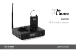
IEM 200
UHF wireless system
user manual
Musikhaus Thomann e.K.
Treppendorf 30
96138 Burgebrach
Germany
Telephone: +49 (0) 9546 9223-0
E-mail: [email protected]
Internet: www.thomann.de
10.10.2013
Table of contents
Table of contents
1
General notes............................................................................................................................................... 5
2
Safety instructions..................................................................................................................................... 8
3
Features and scope of delivery......................................................................................................... 13
4
Installation and starting up................................................................................................................
4.1 General information........................................................................................................................
4.2 Transmitter.........................................................................................................................................
4.3 Transmitter.........................................................................................................................................
4.4 Starting up the system...................................................................................................................
5
Components and functions................................................................................................................ 26
5.1 Transmitter......................................................................................................................................... 26
5.2 Receiver............................................................................................................................................... 33
6
Operating.................................................................................................................................................... 39
6.1 Setting up the transmitter............................................................................................................ 39
6.2 Setting up the receiver................................................................................................................... 41
7
Troubleshooting...................................................................................................................................... 46
18
18
20
23
25
IEM 200
3
Table of contents
8
Technical specifications.......................................................................................................................
8.1 Transmitter.........................................................................................................................................
8.2 Receiver...............................................................................................................................................
8.3 Frequency charts..............................................................................................................................
9
Protecting the environment.............................................................................................................. 60
UHF wireless system
4
49
49
50
52
General notes
1
General notes
This user manual contains important information on safe operation of the device. Read and
follow all safety notes and all instructions. Save this manual for future reference. Make sure
that it is available to all persons using this device. If you sell the device, include the manual for
the next owner.
Our products are subject to a process of continuous development. We therefore reserve the
right to make changes without notice.
Symbols and signal words
This section provides an overview of the symbols and signal words used in this user manual.
IEM 200
5
General notes
Signal word
Meaning
DANGER!
This combination of symbol and signal word
indicates an immediate dangerous situation
that will result in death or serious injury if it is
not avoided.
CAUTION!
This combination of symbol and signal word
indicates a possible dangerous situation that
can result in minor injury if it is not avoided.
NOTICE!
This combination of symbol and signal word
indicates a possible dangerous situation that
can result in material and environmental
damage if it is not avoided.
Warning signs
Type of danger
Warning – high-voltage.
UHF wireless system
6
General notes
Warning signs
Type of danger
Warning – danger zone.
IEM 200
7
Safety instructions
2
Safety instructions
Intended use
This device is intended to be used for the wireless transmission of audio signals to earplugs.
Use the device only as described in this user manual. Any other use or use under other oper‐
ating conditions is considered to be improper and may result in personal injury or property
damage. No liability will be assumed for damages resulting from improper use.
This device may be used only by persons with sufficient physical, sensorial, and intellectual
abilities and having corresponding knowledge and experience. Other persons may use this
device only if they are supervised or instructed by a person who is responsible for their safety.
Safety
DANGER!
Danger for children
Ensure that plastic bags, packaging, etc. are disposed of properly and are not
within reach of babies and young children. Choking hazard!
Ensure that children do not detach any small parts (e.g. knobs or the like) from
the unit. They could swallow the pieces and choke!
Never let children unattended use electrical devices.
UHF wireless system
8
Safety instructions
DANGER!
Electric shock caused by high voltages inside
Within the device there are areas where high voltages may be present. Never
remove any covers.
There are no user-serviceable parts inside.
DANGER!
Electric shock caused by short-circuit
Always use proper ready-made insulated mains cabling (power cord) with a pro‐
tective contact plug. Do not modify the mains cable or the plug. Failure to do so
could result in electric shock/death or fire. If in doubt, seek advice from a regis‐
tered electrician.
IEM 200
9
Safety instructions
CAUTION!
Possible hearing impairment
The use of earphones at high volume over a longer period of time can cause per‐
manent hearing damage.
Adjust the output volume of your audio device to a medium value and use the
earphones no longer than about one hour a day.
NOTICE!
Operating conditions
This device has been designed for indoor use only. To prevent damage, never
expose the device to any liquid or moisture. Avoid direct sunlight, heavy dirt, and
strong vibrations.
UHF wireless system
10
Safety instructions
NOTICE!
Power supply
Before connecting the device, ensure that the input voltage (AC outlet) matches
the voltage rating of the device and that the AC outlet is protected by a residual
current circuit breaker. Failure to do so could result in damage to the device and
possibly injure the user.
Unplug the device before electrical storms occur and when it is unused for long
periods of time to reduce the risk of electric shock or fire.
NOTICE!
Risk of fire due to incorrect polarity
Incorrectly inserted batteries may destroy the device or the batteries.
Ensure that proper polarity is observed when inserting batteries.
IEM 200
11
Safety instructions
NOTICE!
Possible damage by leaking batteries
Leaking batteries can cause permanent damage to the device.
Take batteries out of the device if it is not going to be used for a longer period.
UHF wireless system
12
Features and scope of delivery
3
Features and scope of delivery
The UHF wireless system IEM 200 is suitable for use as in-ear monitoring system, especially for
professional events, on rock stages and concert halls, theatres and musicals.
IEM 200
13
Features and scope of delivery
the t.bone IEM 200 606 MHz
(item no. 278192)
Your UHF wireless system IEM 200 606 MHz consists of the following components:
n 9.5" stereo transmitter IEM 200 T
– Very high sensitivity at very high signal-to-noise ratio
– Inputs: 2 × XLR/1/4" phone combo socket
– Headphones outlets (1/4" phone and 1/8" mini phone sockets) with volume control
– Mounting option for one transmitter in a 19" rack (1 RU)
– Operating voltage supply: AC 100 – 240 V , 50/60 Hz
n Bodypack receiver IEM 200 R (also available separately; item no. 278194)
– Earplug outlet (1/8" mini phone socket) with volume control
– Volume and pan control
– Operating voltage supply: 2 AA cells (LR6, 1.5 V)
n Earplugs EP 4
16 systems can be operated simultaneously. The system operates within a frequency range of
610,250 MHz to 629,750 MHz, divided into four frequency groups.
Included accessories: earpieces in various sizes, batteries and mounting material for rack
mounting
UHF wireless system
14
Features and scope of delivery
the t.bone IEM 200 710 MHz
(item no. 278283)
Your UHF wireless system IEM 200 710 MHz consists of the following components:
n 9.5" stereo transmitter IEM 200 T
– Very high sensitivity at very high signal-to-noise ratio
– Inputs: 2 × XLR/1/4" phone combo socket
– Very high sensitivity at very high signal-to-noise ratio
– Mounting option for one transmitter in a 19" rack (1 RU)
– Operating voltage supply: AC 100 – 240 V , 50/60 Hz
n Bodypack receiver IEM 200 R (also available separately; item no. 278287)
– Headphones outlets (1/4" phone and 1/8" mini phone sockets) with volume control
– Volume and pan control
– Operating voltage supply: 2 AA cells (LR6, 1.5 V)
n Earplugs EP 4
16 systems can be operated simultaneously. The system operates within a frequency range of
714,250 MHz to 733,625 MHz, divided into four frequency groups.
Included accessories: earpieces in various sizes, batteries and mounting material for rack
mounting
IEM 200
15
Features and scope of delivery
the t.bone IEM 200 740 MHz
(item no. 278284)
Your UHF wireless system IEM 200 740 MHz consists of the following components:
n 9.5" stereo transmitter IEM 200 T
– Very high sensitivity at very high signal-to-noise ratio
– Inputs: 2 × XLR/1/4" phone combo socket
– Very high sensitivity at very high signal-to-noise ratio
– Mounting option for one transmitter in a 19" rack (1 RU)
– Operating voltage supply: AC 100 – 240 V , 50/60 Hz
n Bodypack receiver IEM 200 R (also available separately; item no. 278289)
– Headphones outlets (1/4" phone and 1/8" mini phone sockets) with volume control
– Volume and pan control
– Operating voltage supply: 2 AA cells (LR6, 1.5 V)
n Earplugs EP 4
16 systems can be operated simultaneously. The system operates within a frequency range of
744,250 MHz to 763,625 MHz, divided into four frequency groups.
Included accessories: earpieces in various sizes, batteries and mounting material for rack
mounting
UHF wireless system
16
Features and scope of delivery
the t.bone IEM 200 820 MHz
(item no. 278285)
Your UHF wireless system IEM 200 820 MHz consists of the following components:
n 9.5" stereo transmitter IEM 200 T
– Very high sensitivity at very high signal-to-noise ratio
– Inputs: 2 × XLR/1/4" phone combo socket
– Very high sensitivity at very high signal-to-noise ratio
– Mounting option for one transmitter in a 19" rack (1 RU)
– Operating voltage supply: AC 100 – 240 V , 50/60 Hz
n Bodypack receiver IEM 200 R (also available separately; item no. 278290)
– Headphones outlets (1/4" phone and 1/8" mini phone sockets) with volume control
– Volume and pan control
– Operating voltage supply: 2 AA cells (LR6, 1.5 V)
n Earplugs EP 4
16 systems can be operated simultaneously. The system operates within a frequency range of
824,250 MHz to 843,750 MHz, divided into four frequency groups.
Included accessories: earpieces in various sizes, batteries and mounting material for rack
mounting
IEM 200
17
Installation and starting up
4
Installation and starting up
4.1 General information
Unpack and carefully check that there is no transportation damage before using the unit. Keep
the equipment packaging. To fully protect the device against vibration, dust and moisture
during transportation or storage use the original packaging or your own packaging material
suitable for transport or storage, respectively.
Establish all connections as long as the unit is switched off. Use the shortest possible highquality cables for all connections.
UHF wireless system
18
Installation and starting up
Notes on wireless transmission
n This device utilizes frequencies that are not harmonized within the European Union (EU)
and therefore may only be used in certain EU member states. In all European countries, the
frequencies used for the transmission of audio signals are strictly regulated. Before you
start, make sure the frequencies are allowed in the respective country and check whether
the operation must be reported to the appropriate authority.
n Make sure that transmitter and receiver are both tuned to the same channel.
n Never set multiple transmitters to the same channel.
n Make sure that there are no metal objects between the transmitter and receiver.
n Avoid interference from other radio or in-ear systems.
IEM 200
19
Installation and starting up
4.2 Transmitter
XLR connections for signal input
on the transmitter
XLR/1/4" combo sockets are used for the signal inputs on the transmitter. Drawing and table
indicate the XLR pin assignment (balanced wiring) as well as the pin assignment of a suitable
1/4" phone plug.
1
Ground, shielding
2
Positive signal (+)
3
Negative signal (–)
UHF wireless system
20
Installation and starting up
Phone socket for headphones
outlet
1
Signal
2
Ground, shielding
Drawing and table indicate the pin assignment of a 1/8" (top) and 1/4" (bottom) phone plug to
be used.
1
Signal (left)
2
Signal (right)
3
Ground, shielding
IEM 200
21
Installation and starting up
Rack mounting
The unit has been designed for rack mounting in a standard 19-inch rack; it occupies one rack
unit.
Mounting the antenna
Attach the included antenna to the back of the transmitter. To improve the transmission
quality and for adaptation to the specific spatial conditions, the antenna can be rotated and
swivelled.
Audio connection and starting
up
Connect the audio inputs of the transmitter to suitable outlets of your mixing console or
amplifier. Set the volume control (6) to a mid position first.
To achieve best sound quality, a fine adjustment of this control may be required. If the input
level is too high, enable the level attenuation function (Ä ‘Enabling attenuation’ on page 41).
UHF wireless system
22
Installation and starting up
4.3 Transmitter
Inserting batteries into the
receiver
Make sure that the main switch / volume control (17) of the receiver is in ‘OFF’ position.
Simultaneously press on both snap-in locks of the battery compartment at the side and pull it
completely out of the receiver. Open the battery compartment lid by sliding the lid in arrow
direction and then folding it up. Insert the batteries respecting the correct polarity. Close the
battery compartment, the lid must snap-in firmly.
IEM 200
23
Installation and starting up
Rotate the battery compartment into the correct position to receiver; the side of the battery
compartment on which two conductor paths can be seen must point to the top side of the
receiver. Slide the battery compartment back into the receiver until it clicks into position.
Phone socket for earplugs
Drawing and table indicate the pin assignment of a 1/8" TRS mini phone plug for stereo use.
1
Signal (left)
2
Signal (right)
3
Ground, shielding
UHF wireless system
24
Installation and starting up
4.4 Starting up the system
n Make sure that both transmitter and receiver are switched off. The transmitter display is
dark; the main switch / volume control (17) is in ‘OFF’ position.
n Attach the receiver with the clip to your belt or guitar strap.
n Carefully insert the earplugs into the ear canal, observing the markings ‘L’ and ‘R’ for left
and right sides.
n Turn the transmitter on by pressing the main switch (1), turn the receiver on by turning the
main switch / volume control (17). Then test the transmission. Make sure that both trans‐
mitter and receiver are set to the same frequency group and the same channel. If neces‐
sary, adjust the volume on transmitter and receiver as well as the mixer or amp levels.
IEM 200
25
Components and functions
5
Components and functions
5.1 Transmitter
Front panel of the transmitter
UHF wireless system
26
Components and functions
1 POWER
Main switch to turn the device on or off. For turning on, keep this button pressed for one second.
2 Display.
3, 5 [+] / [–]
Buttons for increasing / decreasing the currently indicated value.
4 [SET]
Enter button for menu navigation.
6 VOLUME
Volume control.
7 MONITOR
Headphones volume control.
IEM 200
27
Components and functions
8 PHONES
1/8" mini phone socket (stereo) for headphones connection.
9 PHONES
1/4" phone socket (stereo) for headphones connection.
UHF wireless system
28
Components and functions
Rear panel of the transmitter
10 IEC chassis connector for the mains cable with fuse holder. Next to it, the proper operating voltage is indicated.
11 Indication of the frequency range, in which the unit operates. The specification here must match the specification on
the rear side of the receiver.
IEM 200
29
Components and functions
12 LOOP OUT CH1, CH2
1/4" phone socket (mono). Use these outputs to feed the input signals to further wireless systems or other audio
devices.
13 LEFT CH.1 IN / RIGHT CH.2 IN
XLR / 1/4" combo sockets (left and right channel) for direct connection to a mixing console or another audio device
that is used as signal source.
14 ANTENNA OUT
BNC mounting socket for the supplied UHF antenna. Make sure that the frequency indicated on the antenna matches
the frequency range indicated on the transmitter.
15 UHF antenna.
UHF wireless system
30
Components and functions
Display of the transmitter
A Indicates the frequency that is assigned to the set combination of frequency group
and channel.
B G / CH
Indicates the selected frequency group and the set channel.
C ATT-10dB
Indicates that the attenuation is turned on.
D ST / MONO
Indicates the selected operating mode (stereo or mono).
E FREQ.
Flashing while the frequency is set.
F GROUP
Flashing while the frequency group is set.
G Level indicator for left and right channel.
IEM 200
31
Components and functions
H MODE
Flashing while the operating mode is set.
I ATT
Flashing while the attenuation is set.
J LOCK
Indicates that the unit is locked to prevent unintentional operation.
UHF wireless system
32
Components and functions
5.2 Receiver
Front panel of the receiver
16 Flexible antenna.
17 OFF/ON/VOL
Main switch and volume control. Turn this knob clockwise past the point of resist‐
ance to turn on the receiver. Turn it further to increase the volume.
Turn this knob counter-clockwise to reduce the volume. Turn it further past the
point of resistance to turn off the receiver.
18 L/R
Panorama control.
19 1/8" mini phone socket (stereo) for the earplugs.
20 Display.
21 [SET]
Enter button for menu navigation.
IEM 200
33
Components and functions
22, 23 + / –
Buttons to increase or decrease the currently shown value.
24 Fasteners of the battery compartment for two AA cells (LR6, 1.5 V) or comparable
rechargeable batteries.
UHF wireless system
34
Components and functions
Top panel of the receiver
16 Flexible antenna.
17 OFF/ON/VOL
Main switch and volume control. Turn this knob clockwise past the point of resist‐
ance to turn the receiver on. Turn it further to increase the volume.
Turn this knob counter-clockwise to reduce the volume. Turn it further past the
point of resistance to turn off the receiver.
18 L/R
Panorama control.
19 1/8" mini phone socket (stereo) for the earplugs.
25 Clip to attach the transmitter to the guitar strap or your body, e.g. to the belt.
IEM 200
35
Components and functions
Rear panel of the receiver
16 Flexible antenna.
17 OFF/ON/VOL
Main switch and volume control. Turn this knob clockwise past the point of resist‐
ance to turn the receiver on. Turn it further to increase the volume.
Turn this knob counter-clockwise to reduce the volume. Turn it further past the
point of resistance to turn off the receiver.
18 L/R
Panorama control.
19 1/8" mini phone socket (stereo) for the earplugs.
24 Fasteners of the battery compartment for two AA cells (LR6, 1.5 V) or comparable
rechargeable batteries.
25 Clip to attach the transmitter to the guitar strap or your body, e.g. to the belt.
26 Indication of the frequency range in which the device operates. The specification
here must match the specification printed on the back of the transmitter.
UHF wireless system
36
Components and functions
Display of the receiver
K STEREO
Indicates the selected operating mode (stereo or mono).
L Radio signal strength indicator (one to five bars).
M Indicates that the unit is locked to prevent unintentional operation.
N HF
Indicates the activated high frequency boost function.
O LTD
Indicates that the overload protection (dynamic limiter) is turned on, preventing
clipping and volume peaks.
P Battery level indicator. Replace the batteries when only one bar remains displayed.
Q MUTE
Indicates that no signal is received, e.g. due to a turned off transmitter.
IEM 200
37
Components and functions
R Indicates the frequency that is assigned to the set combination of frequency group
and channel.
S G: / CH:
Indicates the selected frequency group and the set channel.
UHF wireless system
38
Operating
6
Operating
6.1 Setting up the transmitter
Selecting frequency group and
channel
Keep [SET] pressed for some seconds until the field ‘FREQ’ is flashing in the top row of the dis‐
play. Press [SET] again until the field ‘GROUP’ is flashing in the top row of the display and the
field ‘G’ is flashing in the bottom row of the display. Use the [+] / [–] buttons to increase or
decrease the displayed value. When the desired value is shown, press [SET] to confirm the set‐
ting and to proceed to the channel setting.
The field ‘GROUP’ is flashing in the top row of the display and the field ‘CH’ is flashing in the
bottom row.
Use the [+] or [–] button to increase or decrease the displayed value. When the desired value is
shown, press [SET] to confirm the setting and to quit the menu.
In the bottom right area, the display shows the used transmission frequency in MHz that is
assigned to the set combination of frequency group and channel (Ä Chapter 8.3 ‘Frequency
charts’ on page 52).
IEM 200
39
Operating
Transmitter and receiver must be set to the same combination of frequency group
and channel. If you use multiple wireless systems from this device family, for best
results you should assign all systems to the same frequency group, but give each
system a different channel.
Setting the frequency directly
As an alternative to selecting the frequency group and channel, you can also adjust the trans‐
mission frequency directly.
Keep [SET] pressed for some seconds until the field ‘FREQ’ is flashing in the top row of the dis‐
play. Use the [+] / [–] buttons to increase or decrease the displayed value. When the desired
value is shown, press [SET] to confirm the setting and to quit the menu.
In the bottom right area, the display shows the adjusted transmission frequency in MHz.
Selecting the operating mode
Keep [SET] pressed for some seconds until the field ‘FREQ’ is flashing in the top row of the dis‐
play. Press [SET] again until the field ‘MODE’ is flashing in the top row of the display.
Use the [+] / [–] buttons to toggle between mono and stereo operation. When the desired
mode is shown, press [SET] to confirm the setting and to quit the menu.
UHF wireless system
40
Operating
Enabling attenuation
Keep [SET] pressed for some seconds until the field ‘FREQ’ is flashing in the top row of the dis‐
play. Press [SET] again until the field ‘ATT.’ is flashing in the top row of the display.
Use the [+] / [–] buttons to turn a 10 dB attenuation on or off. When the desired mode is
shown, press [SET] to confirm the setting and to quit the menu.
Locking against changes
Keep [SET] pressed for some seconds until the field ‘FREQ’ is flashing in the top row of the dis‐
play. Press [SET] again until the field ‘LOCK’ is flashing in the right column of the display.
Use the [+] / [–] buttons to toggle between locked (display shows ‘Loc ON’ ) and unlocked (dis‐
play shows ‘Loc OFF’ ) operation. In locked mode, the system settings can be viewed, but not
changed. The lock also prevents the unintentional switching on of the unit. When the desired
mode is shown, press [SET] to confirm the setting and to quit the menu.
6.2 Setting up the receiver
Opening the menu
If the receiver is turned on, keep [SET] pressed for some seconds until the menu appears in the
display. Use the [+] / [–] buttons to select a menu item.
IEM 200
41
Operating
Selecting frequency group and
channel
Select the menu item ‘2. Group/Channel’ . Press [SET]. ‘Setup Group’ appears in the first row of
the display.
Use the [+] / [–] buttons to increase or decrease the displayed value. When the desired value is
shown, press [SET] to confirm the setting and to proceed to the channel setting. ‘Setup Chan’
appears in the first row of the display.
Use the [+] / [–] buttons to increase or decrease the displayed value. When the desired value is
shown, press [SET]. The display shows the confirmation prompt ‘Setup is Changed. Do you Want
to Save?’ . Press ‘+’ to apply the changed settings and quit this menu item, or press ‘–’ to leave
this menu item without saving the changes.
In the bottom row, the display shows the used transmission frequency in MHz that is assigned
to the set combination of frequency group and channel.
Transmitter and receiver must be set to the same combination of frequency group
and channel. If you use multiple wireless systems from this device family, for best
results you should assign all systems to the same frequency group, but give each
system a different channel.
UHF wireless system
42
Operating
Setting the frequency directly
As an alternative to selecting the frequency group and channel, you can also adjust the trans‐
mission frequency directly.
Select the menu item ‘1. Frequency’ . Press [SET]. ‘Frequency’ appears in the top row of the dis‐
play.
Use the [+] / [–] buttons to increase or decrease the displayed value. When the desired value is
shown, press [SET]. The display shows the confirmation prompt ‘Setup is Changed. Do you Want
to Save?’ . Press ‘+’ to apply the changed settings and quit this menu item, or press ‘–’ to leave
this menu item without saving the changes.
In the bottom row, the display shows the used transmission frequency in MHz.
Selecting the operating mode
Select the menu item ‘3. Stereo/Mono’ . Press [SET]. ‘Stereo/Mono’ appears in the top row of the
display.
Use the [+] / [–] buttons to toggle between mono and stereo operation. When the desired
mode is shown, press [SET] to confirm the setting and to leave this menu item.
IEM 200
43
Operating
Enabling treble boost
Select the menu item ‘4. Hi Freq. Boost’ . Press [SET]. ‘Hi Freq. Boost’ appears in the top row of
the display.
Use the [+] / [–] buttons to turn the treble boost (increasing the high frequencies) on or off
(display shows ‘ON’ or ‘OFF’ ). If this function is turned on the high frequencies of the trans‐
mitted signal are boosted. The field ‘HF’ appears in the display. When the function is disabled
there is no boost. When the desired mode is shown, press [SET] to confirm the setting and to
leave this menu item.
Enabling overload protection
Select the menu item ‘5. Limiter’ . Press [SET]. ‘Limiter’ appears in the top row of the display.
Use the [+] / [–] buttons to turn the overload protection (dynamic limiter) on or off (display
shows ‘ON’ or ‘OFF’ ). When the desired mode is shown, press [SET] to confirm the setting and
to leave this menu item.
Locking the settings
Select the menu item ‘6. Key lock’ . Press [SET]. ‘Key lock’ appears in the top row of the display.
Use the [+] / [–] buttons to toggle between locked (display shows ‘ON’ ) and unlocked (display
shows ‘OFF’ ) operation. In locked mode, the system settings can be viewed, but not changed.
The display shows a key symbol then. When the desired mode is shown, press [SET] to confirm
the setting and to leave this menu item.
UHF wireless system
44
Operating
Setting the display contrast
Select the menu item ‘7. Contrast’ . Press [SET]. The display shows a symbolic slider.
Use the [+] / [–] buttons to change the contrast in a range of –3 and +3. When the display has
the desired contrast, press [SET] to confirm the setting and to leave this menu item.
Setting the illumination dura‐
tion
Select the menu item ‘8. Light time’ . Press [SET]. The display shows a symbolic slider.
Use the [+] / [–] buttons to choose from the following settings:
n Permanently off (setting ‘OFF’ )
n Permanently on (setting ‘ON’ )
n Turning off after preset time (setting ‘1 sec’ to ‘30 sec’ ).
When the display shows the desired value, press [SET] to confirm the setting and to leave this
menu item. Keep in mind, that the background illumination duration affects the battery life‐
time.
Closing the menu
Select the menu item ‘9. Exit’ and press [SET].
IEM 200
45
Troubleshooting
7
Troubleshooting
In the following we list a few common problems that may occur during operation. We give you
some suggestions for easy troubleshooting:
UHF wireless system
46
Troubleshooting
Symptom
Remedy
No sound
1. Check the power supply of the transmitter and receiver.
2. Make sure that both transmitter and receiver operate in the same frequency
range and that the transmitting antenna is designed for this frequency range.
The frequency range is stated on the devices.
3. Are both transmitter and receiver set to the same frequency group and the
same channel?
4. Check the connection between the transmitter and the connected audio
device (amp, mixer). Is the connected audio device switched on and does the
output signal level of the audio device match the input sensitivity of the trans‐
mitter?
5. Try to improve the transmission by moving the receiver closer to the trans‐
mitter.
Transmission interference
1. Make sure that no metal objects near the transmitter or receiver obstruct the
transmission.
2. Modify the orientation of the antennas.
IEM 200
47
Troubleshooting
Symptom
Remedy
2. If you use more than one wireless system at the same time, check the used
frequency groups and channels.
3. Interference can also be caused by televisions, radios or mobile phones.
The sound is distorted
1. Change the ‘VOLUME’ setting on the transmitter.
2. Turn the overload protection on.
If the procedures recommended above do not succeed, please contact our Service Center. You
can find the contact information at www.thomann.de.
UHF wireless system
48
Technical specifications
8
Technical specifications
8.1 Transmitter
Input
2 × XLR / 1/4" combo sockets (balanced)
Headphones outlet
1/4" phone and 1/8" mini phone sockets (stereo)
Modulation type
Frequency modulation (FM)
Transmission level
10 dBm
Transmission power
10 mW
Input impedance
20 kΩ
Normal audio input level
–4 dBV (0 dB)
6 dBV (–10 dB)
Maximum audio input level
19 dBV (0 dB)
29 dBV (–10 dB)
IEM 200
49
Technical specifications
Gain range
24 dB
NF frequency response
50 Hz…15 kHz (±3 dB)
THD
< 1 % @ 1 kHz
Dynamic range
> 80 dB (A-weighted)
Operating supply voltage
AC 100 – 240 V
Dimensions (W × D × H, without antenna)
212 mm × 220 mm × 44 mm (1 RU)
Weight
1450 g
, 50/60 Hz
8.2 Receiver
Modulation type
Frequency modulation (FM)
Image frequency rejection
> 60 dB
Sensitivity
–102 dBm @ 12 dB SINAD, typical
UHF wireless system
50
Technical specifications
Audio output level
100 mW
Operating supply voltage
2 × AA cells (LR6, 1.5 V)
Dimensions (W × D × H, without antenna)
75 mm × 130 mm × 25 mm
Weight (without batteries)
200 g
IEM 200
51
Technical specifications
8.3 Frequency charts
the t.bone IEM-200 606 MHz – 630 MHz (item no. 278192)
Frequency group A
Channel 1
Channel 2
Channel 3
Channel 4
Channel 5
Channel 6
Channel 7
Channel 8
610.250 MHz
611.500 MHz
612.500 MHz
613.125 MHz
614.250 MHz
615.125 MHz
616.500 MHz
619.500 MHz
Channel 9
Channel 10
Channel 11
Channel 12
Channel 13
Channel 14
Channel 15
Channel 16
620.250 MHz
621.875 MHz
623.000 MHz
624.500 MHz
625.000 MHz
626.750 MHz
627.750 MHz
629.250 MHz
Frequency group B
Channel 1
Channel 2
Channel 3
Channel 4
Channel 5
Channel 6
Channel 7
Channel 8
606.750 MHz
607.375 MHz
609.125 MHz
610.000 MHz
611.250 MHz
612.250 MHz
612.875 MHz
614.000 MHz
Channel 9
Channel 10
Channel 11
Channel 12
Channel 13
Channel 14
Channel 15
Channel 16
614.875 MHz
616.250 MHz
619.250 MHz
620.000 MHz
621.625 MHz
622.750 MHz
624.250 MHz
629.750 MHz
UHF wireless system
52
Technical specifications
the t.bone IEM-200 606 MHz – 630 MHz (item no. 278192)
Frequency group C
Channel 1
Channel 2
Channel 3
Channel 4
Channel 5
Channel 6
Channel 7
Channel 8
607.125 MHz
607.750 MHz
608.625 MHz
609.750 MHz
610.500 MHz
612.125 MHz
612.875 MHz
614.250 MHz
Channel 9
Channel 10
Channel 11
Channel 12
Channel 13
Channel 14
Channel 15
Channel 16
615.000 MHz
616.875 MHz
620.500 MHz
621.875 MHz
622.625 MHz
623.750 MHz
624.375 MHz
629.750 MHz
Frequency group D
Channel 1
Channel 2
Channel 3
Channel 4
Channel 5
Channel 6
Channel 7
Channel 8
606.625 MHz
607.125 MHz
607.875 MHz
609.625 MHz
611.875 MHz
613.125 MHz
613.875 MHz
615.125 MHz
Channel 9
Channel 10
Channel 11
Channel 12
Channel 13
Channel 14
Channel 15
Channel 16
616.875 MHz
617.375 MHz
618.875 MHz
619.375 MHz
620.125 MHz
622.250 MHz
623.625 MHz
629.625 MHz
IEM 200
53
Technical specifications
the t.bone IEM-200 710 MHz – 734 MHz (item no. 278283)
Frequency group A
Channel 1
Channel 2
Channel 3
Channel 4
Channel 5
Channel 6
Channel 7
Channel 8
714.250 MHz
715.500 MHz
716.500 MHz
717.125 MHz
718.250 MHz
719.125 MHz
720.500 MHz
723.500 MHz
Channel 9
Channel 10
Channel 11
Channel 12
Channel 13
Channel 14
Channel 15
Channel 16
724.250 MHz
725.875 MHz
727.000 MHz
728.500 MHz
729.000 MHz
730.750 MHz
731.750 MHz
733.250 MHz
Frequency group B
Channel 1
Channel 2
Channel 3
Channel 4
Channel 5
Channel 6
Channel 7
Channel 8
710.750 MHz
711.375 MHz
713.125 MHz
714.000 MHz
715.250 MHz
716.250 MHz
716.875 MHz
718.000 MHz
Channel 9
Channel 10
Channel 11
Channel 12
Channel 13
Channel 14
Channel 15
Channel 16
718.875 MHz
720.250 MHz
723.250 MHz
724.000 MHz
725.625 MHz
726.750 MHz
728.250 MHz
733.750 MHz
UHF wireless system
54
Technical specifications
the t.bone IEM-200 710 MHz – 734 MHz (item no. 278283)
Frequency group C
Channel 1
Channel 2
Channel 3
Channel 4
Channel 5
Channel 6
Channel 7
Channel 8
711.125 MHz
711.750 MHz
712.625 MHz
713.750 MHz
714.500 MHz
716.125 MHz
716.875 MHz
718.250 MHz
Channel 9
Channel 10
Channel 11
Channel 12
Channel 13
Channel 14
Channel 15
Channel 16
719.000 MHz
720.875 MHz
724.500 MHz
725.875 MHz
726.625 MHz
727.750 MHz
728.375 MHz
733.750 MHz
Frequency group D
Channel 1
Channel 2
Channel 3
Channel 4
Channel 5
Channel 6
Channel 7
Channel 8
710.625 MHz
711.125 MHz
711.875 MHz
713.625 MHz
715.875 MHz
717.125 MHz
717.875 MHz
719.125 MHz
Channel 9
Channel 10
Channel 11
Channel 12
Channel 13
Channel 14
Channel 15
Channel 16
720.875 MHz
721.375 MHz
722.875 MHz
723.375 MHz
724.125 MHz
726.250 MHz
727.625 MHz
733.625 MHz
IEM 200
55
Technical specifications
the t.bone IEM-200 740 MHz – 764 MHz (item no. 278284)
Frequency group A
Channel 1
Channel 2
Channel 3
Channel 4
Channel 5
Channel 6
Channel 7
Channel 8
744.250 MHz
745.500 MHz
746.500 MHz
747.125 MHz
748.250 MHz
749.125 MHz
750.500 MHz
753.500 MHz
Channel 9
Channel 10
Channel 11
Channel 12
Channel 13
Channel 14
Channel 15
Channel 16
754.250 MHz
755.875 MHz
757.000 MHz
758.500 MHz
759.000 MHz
760.750 MHz
761.750 MHz
763.250 MHz
Frequency group B
Channel 1
Channel 2
Channel 3
Channel 4
Channel 5
Channel 6
Channel 7
Channel 8
740.750 MHz
741.375 MHz
743.125 MHz
744.000 MHz
745.250 MHz
746.250 MHz
746.875 MHz
748.000 MHz
Channel 9
Channel 10
Channel 11
Channel 12
Channel 13
Channel 14
Channel 15
Channel 16
748.875 MHz
750.250 MHz
753.250 MHz
754.000 MHz
755.625 MHz
756.750 MHz
758.250 MHz
763.750 MHz
UHF wireless system
56
Technical specifications
the t.bone IEM-200 740 MHz – 764 MHz (item no. 278284)
Frequency group C
Channel 1
Channel 2
Channel 3
Channel 4
Channel 5
Channel 6
Channel 7
Channel 8
741.125 MHz
741.750 MHz
742.625 MHz
743.750 MHz
744.500 MHz
746.125 MHz
746.875 MHz
748.250 MHz
Channel 9
Channel 10
Channel 11
Channel 12
Channel 13
Channel 14
Channel 15
Channel 16
749.000 MHz
750.875 MHz
754.500 MHz
755.875 MHz
756.625 MHz
757.750 MHz
758.375 MHz
763.750 MHz
Frequency group D
Channel 1
Channel 2
Channel 3
Channel 4
Channel 5
Channel 6
Channel 7
Channel 8
740.625 MHz
741.125 MHz
741.875 MHz
743.625 MHz
745.875 MHz
747.125 MHz
747.875 MHz
749.125 MHz
Channel 9
Channel 10
Channel 11
Channel 12
Channel 13
Channel 14
Channel 15
Channel 16
750.875 MHz
751.375 MHz
752.875 MHz
753.375 MHz
754.125 MHz
756.250 MHz
757.625 MHz
763.625 MHz
IEM 200
57
Technical specifications
the t.bone IEM-200 820 MHz – 844 MHz (item no. 278285)
Frequency group A
Channel 1
Channel 2
Channel 3
Channel 4
Channel 5
Channel 6
Channel 7
Channel 8
824.250 MHz
825.500 MHz
826.500 MHz
827.125 MHz
828.250 MHz
829.125 MHz
830.500 MHz
833.500 MHz
Channel 9
Channel 10
Channel 11
Channel 12
Channel 13
Channel 14
Channel 15
Channel 16
834.250 MHz
835.875 MHz
837.000 MHz
838.500 MHz
839.000 MHz
840.750 MHz
841.750 MHz
843.250 MHz
Frequency group B
Channel 1
Channel 2
Channel 3
Channel 4
Channel 5
Channel 6
Channel 7
Channel 8
820.750 MHz
821.375 MHz
823.125 MHz
824.000 MHz
825.250 MHz
826.250 MHz
826.875 MHz
828.000 MHz
Channel 9
Channel 10
Channel 11
Channel 12
Channel 13
Channel 14
Channel 15
Channel 16
828.875 MHz
830.250 MHz
833.250 MHz
834.000 MHz
835.625 MHz
836.750 MHz
838.250 MHz
843.750 MHz
UHF wireless system
58
Technical specifications
the t.bone IEM-200 820 MHz – 844 MHz (item no. 278285)
Frequency group C
Channel 1
Channel 2
Channel 3
Channel 4
Channel 5
Channel 6
Channel 7
Channel 8
821.125 MHz
821.750 MHz
822.625 MHz
823.750 MHz
824.500 MHz
826.125 MHz
826.875 MHz
828.250 MHz
Channel 9
Channel 10
Channel 11
Channel 12
Channel 13
Channel 14
Channel 15
Channel 16
829.000 MHz
830.875 MHz
834.500 MHz
835.875 MHz
836.625 MHz
837.750 MHz
838.375 MHz
843.750 MHz
Frequency group D
Channel 1
Channel 2
Channel 3
Channel 4
Channel 5
Channel 6
Channel 7
Channel 8
820.625 MHz
821.125 MHz
821.875 MHz
823.625 MHz
825.875 MHz
827.125 MHz
827.875 MHz
829.125 MHz
Channel 9
Channel 10
Channel 11
Channel 12
Channel 13
Channel 14
Channel 15
Channel 16
830.875 MHz
831.375 MHz
832.875 MHz
833.375 MHz
834.125 MHz
836.250 MHz
837.625 MHz
843.625 MHz
IEM 200
59
Protecting the environment
9
Protecting the environment
Disposal of the packaging mate‐
rial
For the transport and protective packaging, environmentally friendly materials have been
chosen that can be supplied to normal recycling.
Ensure that plastic bags, packaging, etc. are properly disposed of.
Do not just dispose these materials with your normal household waste, but make sure that
they are fed to a recovery. Please follow the notes and markings on the packaging.
Disposal of batteries
Batteries must not be disposed of as domestic waste or thrown into fire. Dispose of the bat‐
teries according to national or local regulations regarding hazardous waste. To protect the
environment, dispose of empty batteries at your retail store or at appropriate collection sites.
UHF wireless system
60
Protecting the environment
Disposal of your old device
This device is subject to the European directive 2012/19/EU. Do not dispose the device with
your normal household waste.
Dispose this device through an approved waste disposal firm or through your local waste
facility. When discarding the device, comply with the rules and regulations that apply in your
country. If in doubt, consult your local waste disposal facility.
IEM 200
61
Notes
UHF wireless system
62
Musikhaus Thomann e.K. · Treppendorf 30 · 96138 Burgebrach · Germany · www.thomann.de