1
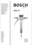
USOO5813972A
Ulllted States Patent [19]
[11] Patent Number:
Nazarian et al.
[45]
[54]
[75]
5,813,972
Date of Patent:
Sep. 29, 1998
MEDICAL PERFUSION SYSTEM WITH
5,572,658
DATA COMMUNICATIONS NETWORK
5,609,770
3/1997 Zimmerman et 91
5,622,429
4/1997
5,627,531
5/1997 Posso et al. ............................ .. 341/22
Timothy
Kriewall, Castle Rock,
Colo.; Richard A. Griewski, Canton
0 609 688
0 690 291
8/1994
3/1996
European Pat. Off. ...... .. G06F 15/42
European Pat O?- -
Township Nlich~
’
O 745 348
O 748 609
12/1996
12/1996
European Pat. Off. ........ .. A61B 5/00
European Pat. Off.
A61B 5/00
Inventors: Richard A_ Nazarian, Golden Valley;
11/1996 Mohr et al. ...................... .. 395/18202
HeinZe
.............. ..
..
Watts, Woodbury, all of M1nn.;
.
_
.
.
.
[73] Asslgnee' xmnefsotta Mlmgg and
M?“ ac “nng
S P 1
ompany’
L
au>
O 762 815
3/1997
0 768 060
4/1997 European Pat. Off.
European Pat. Off.
24 55 229
5/1976
.
HO5K 5/00
.. A61B 5/215
Germany ...................... .. A61M 1/03
mn.
OTHER PUBLICATIONS
[21] Appl' NO‘: 723’504
[22] Filed:
Sep. 30, 1996
Jostra HL20 User’s Manual, Jostra AB, Sweden, 120 pages,
undated
6
Jostra HL20 Technical manual, sep. 9, 1994, 46 pages.
[51]
Int. Cl.
.................................................... .. A61M 1/00
[52]
US. Cl. .............................................................. .. 600/17
[58]
Field of Search ................................ .. 600/17,6(1)2;2183;
(List Continued on next page)
Primary Examiner_w?ham E‘ Kamm
’
[56]
Assistant Examiner—Kennedy J. SchaetZle
References Cited
Attorney, Agent, or Ftrm—Gary L. Grlswold; Stephen W.
Bauer; Martm J. Hlrsch
[57]
ABSTRACT
U.S. PATENT DOCUMENTS
4,722,224
2/1988
Scheller et al. ......................... ..
5,001,642 3/1991 BOtZenhardt et a1_
5,059,167 10/1991 Lundquist et a1,
73/599
_
364/431_12
____ __ 600/17
_
_
_
_
A medical perfusion system for use in connection w1th the
medical treatment of a patient is provided with a ?rst type of
5,105,441
4/1992 Borst et al. ......... ..
375/17
perfusion device in the form of a blood pump adapted to
5,111,460
5/1992 Botlenhardt et al-
371/29 1
pump blood through a ?uid conduit connected to the patient,
572167674
6/1993 Pet?“ a1~ ~~~~~~~~~~ ~~
371/29 5
a second type of perfusion device in the form of a sensor
2222410
6/1993 Holzmierdet a1‘
5,341,497
8/1994
303348
27/445‘
4/1994 Botzen at tet a‘
Younger .......... ..
573877122
2/1995 Goldberger et aL __
5,444,626
5,448,180
8/1995 Schenk ____________ __
9/1995 Kienzler et a1,
5,448,561
5,493,515
9/1995 Kaiser et al.
2/1996 Bat§heldef et a1- --
5:499:36
3/1996 Prels ct a1~ ~~~~~~ ~~
,
i/i‘bler et a1‘
,
ayer
through the ?uid conduit and to generate a sensing signal
395/575
573577518 10/1994 Peter ___________ n
2’;
adapted to sense a condition relating to the pumping of blood
39 62
1
. . . . . . . .
5,539,778
7/1996 KienZler et al. ..
d. .
d
d
work for operat1vely mterconnectmg the perfusion devlces.
The perfusion system also includes means for transmitting
messages in the form of digital data packets among the
370/85 1
364/550
perfusion devices over the data communications network
and a controller operatively coupled to the perfusion devices
395/182 02
via the data communications network, the controller having
an input device for accepting pump control commands
-
u 39500017
relatmg to the blood pump from an operator.
375/317
15 Claims, 15 Drawing Sheets
MAIN
—~2o
CONTROLLER
10
30L
%
30k
1
HT
EXTENDER
CONTROLLER
30b
409 52g
EXTENDER
325
CONTROLLER
32b
30:
ll [34a
NODE
CONTROLLER
and
a: 40a
314b
NODE
CONTROLLER
306
w 40b
u
309
341:
J
34d
NODE
CONTROLLER
NODE
CONTROLLER
3 0'
400
30h
34
e
NODE
CONTROLLER
3 Di
/34f
NODE
CONTROLLER
3 0l
@
40f
2f
TEMPERATURE
SENSOR
50a
.
439/353
5,564,108 10/1996 Hunsaker et al. .................... .. 395/800
(2“
.
a 'ata COIIIIIIUHICZIIIOHS'HCI
364/431_04
____ __ 326/15
. . . . . . . . ..
6/1996 Dais et a1‘ '
h
re atmg to t e con 1t1on, an
364/
575247213
.
371/11 2
50s
501
5,813,972
Page 2
OTHER PUBLICATIONS
Cobe/Stockert Perfusion System, Technical Handbook,
Cobe Laboratories, Inc., Rev. A, pp. 1—1—1—33; 2—1—
SarnsTM 9000 Perfusion System Operators Manual, Sep.
1995, pp. i—v; A—C; 1.1—1.11;2.1—2.11;3.1—3.11;4.1—4.10;
2—66; 3—1—3—93; 4—1—4—105; and 5—1—5—29, undated
5.1—5.7; 6.1—6.9; 7.1—7.6; 8.1—8.6; 9.1—9.4; 10.1—10.4;
11.1—11.3; 12.1—12.4; 13.1—13.2; 14.1—14.3; 15.1;
16.1—16.4; 17.1—17.14; 18.1—18.6; 19.1—19.19; 20.1—20.56,
S 3 System, HerZ—Lungen—Maschine irn Modularsystern,
GebrauchsanWeisung, Table of Contents, pp. I—XXI; pp.
including Additional insert, 4 sheets; and IndeX, pp.
21.1—21.4.
3MTMSarnsTM Modular Perfusion System 8000 Operators
Manual, May 1996, pp. i—v; 1.1—1.22; 2.1—2.14; 3.1—3.10;
4.1—4.10; 5.1—5.2; 6.1—6.2; 7.1—7.5; 8.1—8.4; 9.1—9.9;
10.1—10.68; and IndeX, pp. 11.1—11.3.
(prior art).
1—1—1—2;
2—1—2—28;
3—1—3—14;
4—1—4—22;
5—1—5—262; 6—1—6—22; 7—1—7—8; 8—1—8—16; A—1—
A—18, undated.
“BOC Puts Ohrneda Health Care Business Up for Sale”;
Medical Devices, Diagnostics & Instrurnentation Reports
The Gray Sheet; vol. 23, No. 30; Jul. 28, 1997.
U.S. Patent
Sep.29,1998
Sheet 2 0f 15
5,813,972
40
70
82
4.
7O @
7O
86
68
FIG. 2
FIG. 4
F|G.3
FIG. 5
62
409
40h
6930
0
4Oc122u
a a
54
%
40d
L; y_
4Oe
/1/
40b /
84
v
0
0
¢
o o o 0
FIG. 6
72‘86 74 76
¢
84
F|G.7
88
U.S. Patent
Sep.29,1998
20
(100
Sheet 3 0f 15
102
104
\
MP
11a
283E:
NON
VOLATILE
RAM
MEMORY
*
i
‘F
i
NETWORK
DRAWING
CONTROL-
CONTROL-
LER
LER
l
\10s
120
5,813,972
"\112
(114
-> DISPLAY
l/O
(
\103
(
INPUT
110
/30m
341 g
NODE
CONTROLLER
H 134h
NODE
CONTROLLER
?~3oa
116
U /341
/34]
NODE
CONTROLLER
NODE
CONTROLLER
?\3Oc
?\30d
?\30b
32a
\
135
133
DRIVER
T
30a
CONTROLLER —>
sw
##132
130/
134
134
FIG. 10
30C
U.S. Patent
Sep.29,1998
Sheet 4 0f 15
5,813,972
34a
ENABLE/
DISABLE
\
DATA
/134
+24V
—--152
CODE
___..144
150
154
+5V
r120a
-120b
152
158
-
I—)
_»
GND
~120c
164
1
SW
CONTROLLER
)
'
l‘\
f'\
1
\14o
Y
<--OR|vER
~_
170
-——120a
r--12ob
———-“2°¢
#133
DATA
+24
+5
GND
40a
DATA
133
|'-152
1 4
f
DRIVER
T
+24v +5v GND
XCVR
i
f
120a
\
120!)
186
POWER
CONTROLLER
180/ T
__120c
SUPPLY
——~
t
MEMQRY
DEVICE
/ INTERFACE
192
194
FIG. 12
182
U.S. Patent
Sep. 29, 1998
5,813,972
Sheet 5 0f 15
/ 200
CONFIGURE
I
204
SELECT FILE
SELECT TYPE OF
PERFUSION CIRCUIT
/
DISPLAY
/ 208
PERFUSION CIRCUIT
SELECT oPTIoN
/ 21°
226
ADD
DEVICE?
CONFIGURE
DEVICE?
/
SELECT
DEVICE TYPE
/
DISPLAY CURRENT
CONFIGURATION
l / 216
l /224
SELECT POSITION
CHANGE
CONFIGURATION
I
DISPLAY DEVICE
IN PERFUSION
CIRCUIT
/21s
I
FIG. 13A
DISPLAY
DATA?
228
DATA
AVAILABLE?
/230
DISPLAY
DATA
No
U.S. Patent
Sep.29,1998
Sheet 6 0f 15
5,813,972
260
AUTO MODE?
ONLY ONE
MATCH?
Yes
SELECT
ALREADY
CONFIGURED?
CONFIGURATION
__>
274
CONFIGURE DEVICE / 276
I
SELECT POSITION
POSITION
KNOWN?
_/ 263
DISPLAY DEVICE IN / 270
PERFUSION CIRCUIT
FIG. 13B
U.S. Patent
Sep.29,1998
Sheet 7 0f 15
5,813,972
[280
DECODE DEVICE TYPE
AND PHYSICAL ADDRESS
284
FULL POWER?
Yes
ALLOCATE LOGICAL
ADDRESS
/ 286
V
ENCODE STARTUP
/ 288
GRANTED MESSAGE
V
TRANSMIT MESSAGE
/ 29°
292
LOCAL DEV ICE?
Y es
/ 294
ENABLE POWER VIA
LOCAL NODE CONTROLLER
ENCODE NODE ENABLE
MESSAGE
V
TRANSMIT MESSAGE
/
298
FIG. 13C
U.S. Patent
Sep.29,1998
Sheet 8 0f 15
5,813,972
300
/
STATUS
REQUEST
.
33o
ENCODE STATUS
REQUEST MESSAGE
/ 302
BROADCAST STATUS
/ 304
\\
REQUEST MESSAGE
*
306
START TIME-OUT
/
PERIOD
H G- 1 3D
DISCONNECT VIA LOCAL
NODE CONTROLLER
/ 310
I
RECEIVE STATUS
$6
DETERMINE LOGICAL ADDRESS / 312
FROM STATUS MESSAGE
I
DETERMINE STATUS
FROM MESSAGE
/ s14
ENCODE
DISCONNECT MESSAGE
l /338
TRANSMIT MESSAGE
316
STATUS OK?
RESPOND TO
STATUS CONDITION
G. 1 3F
@3
FIG. 13E
U.S. Patent
Sep. 29, 1998
Sheet 9 0f 15
5,813,972
[350
352
CONTROL
COMMAND?
ENCODE CONTROL
MESSAGE
/354
T
BROADCAST
CONTROL MESSAGE
RESET
ALARM?
ENCODE ALARM
RESET MESSAGE
/ 360
+
BROADCAST ALARM /
362
RESET MESSAGE
RESET
SYSTEM?
ENCODE SYSTEM
RESET MESSAGE
/ 366
BROADCAST SYSTEM /
RESET MESSAGE
FIG. 136
368
U.S. Patent
Sep.29,1998
Sheet 10 0f 15
5,813,972
/ 370
UPDATE
DISPLAY
_)
LOG
EVENT
374
UPDATE
DISPLAY
37s
‘’
380
STARTUP
——>
382
PROCESS
UPDATE
MESSAGE +
DISPLAY
386
REQUEST?
LOG
DATA
ass
PROCESS _)
UPDATE
REQUEST
DISPLAY
394
LOG
_>
\
396
FIG. 13H
STATUS
39o
_“)
U.S. Patent
Sep.29,1998
Sheet 11 0f 15
5,813,972
FIG. 14A
FIG. 14B
U.S. Patent
Sep. 29, 1998
Sheet 12 0f 15
CEXTENDER STARTUP)
PERFORM INTERNAL
SELF-TESTS
424
5,813,972
/ 420
/ 422
No
Yes
TEST BUS
-/' 426
42s
No
Yes
START PERIODIC
TRANSMISSION To
NODE CONTROLLER
BROADCAST
/ 43o
ERROR
MESSAGE
‘
*
WAIT FOR
\
PHYSICAL ADDRESS
436
/
432
434
ALL TESTS
PASSED?
BROADCAST
STARTUP REQUEST
_/ 438
WAIT FOR STARTUP
GRANTED MESSAGE
/ 44°
WAIT FOR
FULL POWER
/ 442
MEASURE vOLTAGES
/ 444
AND CURRENT
446
N
0
Yes
FIG. 1 5A
U.S. Patent
Sep.29,1998
/
DECODE PHYSICAL
ADDRESS OF MESSAGE
/ 452
Sheet 13 0f 15
5,813,972
DISCONNECT
DECODE PHYSICAL
ADDRESS OF MESSAGE
454
464
No
Yes 456
/ 462
NO
Yes
4266
TRANSMIT ENABLE SIGNAL
TO NODE CONTROLLER
TRANSMIT DISABLE SIGNAL
To NQDE CONTROLLER
FIG. 158
FIG. 15C
U.S. Patent
Sep. 29, 1998
5,813,972
Sheet 14 0f 15
470
CODE VALID?
Yes
/
RESTART
TIME-OUT TIMER
490
476
/
TRANSMIT PHYSICAL
ADDRESS
478
/
CONNECT DEVICE
TO DATA BUS
DISCONNECT DEVICE / 492
FROM DATA BUS
I
ENABLE?
DISCONNECT DEVICE / 494
FROM FULL POWER
SUPPLY FULL
POWER TO DEVICE
FIG. 16B
DISCONNECT DEVICE
FROM DATA BUS
W [486
DISCONNECT DEVICE
FROM FULL POWER
FIG. 16A
U.S. Patent
Sep.29,1998
Sheet 15 0f 15
52
o\
C POD STARTUP D 550\
5,813,972
I
DECODE MESSAGE
PERFORM INTERNAL
522 /
SELF-TESTS
552
v
524
N°
TRANSMIT CONTROL
SIGNAL TO DEVICE
554 /
Yes
526 _/
i)
TEST BUS
528
FIG. 1 7B
560
N°
530
Yes,__,/
START PERIODIC
@
TRANSMISSION To
BROADCAST
NoDE coNTRoLLER
ERROR
MESSAGE
ENCODE ALARM
MESSAGE
V
A
WAIT FOR
\
562\
/ 532
T
PHYSICAL ADDRESS
536
BROADCAST
ALARM MESSAGE
f
564
ALL TESTS
PASSED?
570
538 \
BROADCAST
STARTUP REQUEST
540 \
WAIT FOR STARTUP
GRANTED MESSAGE
*
542 \
@
572
\
WAIT FOR
FULL POWER
+
544\
FIG. 17C
'
SIGNAL
*
574 \ ENCODE MESSAGE
WITH SENSING
SIGNAL
MEASURE voLTAGES
AND CURRENT
READ SENS'NG
Y
576 \
BROADCAST
MESSAGE
FIG. 17D
5,813,972
1
2
MEDICAL PERFUSION SYSTEM WITH
DATA COMMUNICATIONS NETWORK
In another aspect, the invention is directed to an adapter
pod for use in a medical perfusion system having a data
communications netWork With a plurality of connection
points each having a substantially identical netWork con
nector. The adapter pod includes a common connector
adapted to be connected to one of the netWork connectors,
a device connector adapted to be connected to a perfusion
device, and means for generating a message in the form of
BACKGROUND OF THE INVENTION
The present invention is directed to a medical perfusion
system adapted to handle the selective oxygenation, ?ltering
and recirculation of blood in connection With various medi
cal procedures.
A conventional perfusion system may be used to
oxygenate, ?lter, and/or recirculate the blood of a patient
during a medical procedure. Such a perfusion system may
10
to those of ordinary skill in the art in vieW of the detailed
have a ?uid conduit that removes blood from the patient
description of the preferred embodiments, Which is made
during the medical procedure, a separate ?uid conduit that
With reference to the draWings, a brief description of Which
returns blood to the patient, one or more blood pumps that
pump blood through the conduits, and a plurality of sensing
a digital data packet.
These and other features of the invention Will be apparent
is provided beloW.
15
devices, such as How sensors and/or level sensors associated
BRIEF DESCRIPTION OF THE DRAWINGS
With blood pumps. The perfusion system may also include
air embolus sensors, temperature sensors, ?oW occluders,
FIG. 1 is a block diagram of a preferred embodiment of
a perfusion system in accordance With the invention;
FIG. 2 is a perspective vieW of the main controller shoWn
etc.
Typically, a perfusion system is provided With a con?gu
ration speci?cally designed to be used for a particular
purpose. For example, one perfusion system may be spe
ci?cally designed as a full-function heart/lung machine,
schematically in FIG. 1;
FIG. 3 is a perspective vieW of one of the netWork
extenders shoWn schematically in FIG. 1;
While another perfusion system may be speci?cally designed
as a ventricular-assist system. Although it may be possible to
FIG. 4 is a perspective vieW of one of the adapter pods
25
convert a perfusion system designed for one purpose to a
perfusion system usable for a different purpose, such recon
shoWn schematically in FIG. 1;
FIGS. 5—7 illustrate a number of connector con?gura
tions;
?guration is generally difficult and/or time-consuming.
FIG. 8 is a perspective vieW of the main controller shoWn
schematically in FIG. 1 With tWo netWork extenders and
SUMMARY OF THE INVENTION
The invention is directed to a medical perfusion system
for use in connection With the medical treatment of a patient.
eight adapter pods plugged therein;
The perfusion system includes a ?rst type of perfusion
schematically in FIG. 1;
device in the form of a blood pump adapted to pump blood
through a ?uid conduit connected to the patient, a second
type of perfusion device in the form of a sensor adapted to
sense a condition relating to the pumping of blood through
FIG. 9 is a block diagram of the main controller shoWn
FIG. 10 is a block diagram of one of the extender
35
controllers shoWn schematically in FIG. 1;
FIG. 11 is a block diagram of one of the node controllers
shoWn schematically in FIG. 1;
the ?uid conduit and to generate a sensing signal relating to
FIG. 12 is a block diagram of one of the adapter pods
the condition, and a data communications netWork for
operatively interconnecting the perfusion devices. The per
shoWn schematically in FIG. 1;
fusion system also includes means for transmitting messages
FIGS. 13A—13H are ?oWcharts illustrating the operation
of the main controller shoWn in FIG. 1;
FIGS. 14A—14B are exemplary illustrations of a pair of
in the form of digital data packets among the perfusion
devices over the data communications netWork and a con
troller operatively coupled to the perfusion devices via the
data communications netWork, the controller having an
input device for accepting pump control commands from an
45
FIGS. 15A—15C are ?oWcharts illustrating the operation
of the extender controllers shoWn in FIG. 1;
FIGS. 16A—16B are ?oWcharts illustrating the operation
of the node controllers shoWn in FIG. 1; and
FIGS. 17A—17D are ?oWcharts illustrating the operation
of the adapter pods shoWn in FIG. 1.
operator.
The data communications netWork may be provided With
a plurality of netWork connectors, each of Which has an
identical connector con?guration, and the perfusion system
may include at least tWo adapter pods, each of Which has a
common connector adapted to be coupled to one of the
netWork connectors and a device connector adapted to be
coupled to one of the perfusion devices. The message
transmitting means may include means for generating a 55
message containing a control command for the pump and
means for generating a message containing data relating to
the sensed condition.
The controller may include a plurality of netWork
connectors, and the data communications netWork may
connectors.
DETAILED OF THE PREFERRED
EMBODIMENTS
FIG. 1 illustrates a preferred embodiment of a medical
perfusion system 10 in accordance With the invention. The
perfusion system 10 is adapted to handle the selective
oxygenation, ?ltering and recirculation of blood in connec
tion With a number of different medical procedures. The
perfusion system 10 may be placed in a number of different
con?gurations, each of Which corresponds to a different
include a netWork extender having a netWork connector
adapted to be coupled to one of the netWork connectors of
the controller, a plurality of extender connectors adapted to
be connected to the common connectors of the adapter pods,
and a data bus electrically interconnecting the netWork
connector of the netWork extender With each of the extender
perfusion circuit images generated on the display device of
FIG. 9 during operation of the perfusion system;
medical procedure. For example, the perfusion system 10
65
may be con?gured as a full-function heart/lung machine, a
ventricular assist system, or a single-pump system that can
be used for various purposes, such as to perform blood
aspiration or myocardial protection during surgery.
5,813,972
4
3
Referring to FIG. 1, the main controller 20 is connected
pod 40 has a hexahedral housing With one side 82 on Which
a connector 84 is disposed and an opposite side on Which a
connector 86 is disposed. The connector 86 is identical to the
to a netWork extender 22a via a data/poWer bus 30a and to
a netWork extender 22b via a data/poWer bus 30b. The
netWork extender 22a includes an extender controller 32a
connected to three node controllers 34a, 34b, 34c via a
data/poWer bus 30c. The node controller 34a is connected
via a data/poWer bus 30a' to an adapter pod 40a, Which is in
turn connected to a perfusion device 50 in the form of a How
sensor 50a via a bidirectional data/poWer line 52a. The node
controller 34b is connected via a data/poWer bus 306 to an
adapter pod 40b, Which is connected to an air embolus
connectors 72 described above (and shoWn in FIG. 6).
The connector 84 is adapted to be connected to a device
10
sensor 50b via a bidirectional line 52b. The node controller
different type of perfusion device 50 (the pumps 50c, 50g
34c is connected via a data/poWer bus 30f to an adapter pod
may be different types of pumps, such as a roller pump or a
40c, Which is connected to a blood pump 50c via a bidirec
tional line 52c.
The netWork extender 22b includes an extender controller
32b connected to three node controllers 34d, 34e, 34f via a
15
connected to a pressure sensor 50d via a bidirectional line
pods 40, it should be noted that any of the adapter pods 40
52d. The node controller 346 is connected via a data/poWer
bus 30i to an adapter pod 406, Which is connected to a
may be plugged into any of the connectors 60, 70. As a
result, any combination of perfusion devices 50 may be
temperature sensor 506 via a bidirectional line 526. The node
connected to the main controller 20.
controller 34f is connected via a data/poWer bus 30j to an
25
via a bidirectional line 52]”.
The main controller 20 is operatively coupled to a blood
pump 50g via a bidirectional line 52g connected to an
designed to be used in a medical perfusion system, including
but not limited to a blood pump such as a centrifugal or roller
pump, a ?oW sensor, a pressure sensor, a temperature sensor,
a level sensor, an air embolus sensor or an occluder.
Mechanical Structure of Network Components
FIG. 2 is a perspective vieW of a portion of one mechani
cal embodiment of the main controller 20. Referring to FIG.
2, the main controller 20 has four netWork connectors 60,
FIG. 8 illustrates the main controller 20 having the
netWork extenders 22 and the adapter pods 40 connected to
it. Each of the adapter pods 40 of FIG. 8 Would be connected
to a respective one of the perfusion devices 50 shoWn in FIG.
adapter pod 40g. The pod 40g is connected to the main
controller 20 via a data/poWer bus 30k. The main controller
20 is operatively coupled to a level sensor 50h via a
bidirectional line 52h connected to an adapter pod 40h,
Which is connected to the main controller 20 via a data/
poWer bus 301.
As used herein, the term “perfusion device” is a device
centrifugal pump), the connector 84 disposed on each of the
adapter pods 40 may have a different connector con?gura
tion.
Since the connectors 60 of the main controller 20 and the
connectors 70 of the netWork extenders 22 have the same
connector con?guration as the connector 86 of the adapter
data/poWer bus 30g. The node controller 34a' is connected
via a data/poWer bus 30h to an adapter pod 40d, Which is
adapter pod 40f, Which is connected to a How occluder 50f
connector (not shoWn) that is associated With one of the
perfusion devices 50 described above. The connector 84 has
a different connector con?guration than the connectors 60,
70, 72, 86. One example of the structure of the connector 84
is shoWn in FIG. 7 to include six conductive pins 88. Since
each of the adapter pods 40 is adapted to be connected to a
35
1 via a respective connector (not shoWn) attached to the
perfusion device 50 by a cable.
Although the form of the netWork extenders 22 shoWn in
FIGS. 3 and 8 makes the resulting control unit compact,
netWork extenders having different structures could be used.
For example, instead of having the connector 72 ?xed on the
housing 66, the connector 72 could be connected to the
housing 66 via a cable. Alternatively, the housing 66 could
be eliminated, and the connectors 70, 72 could be intercon
nected via cables.
Electronics
FIG. 9 is a block diagram of the main controller 20 shoWn
schematically in FIG. 1. Referring to FIG. 9, the main
controller 20 has a microprocessor (MP) 100, a random
access memory (RAM) 102, a nonvolatile memory 104 such
Which are shoWn schematically. Each of the netWork con 45 as a hard disk or a ?ash RAM, a netWork controller 106, a
draWing controller 108, and an input/output (I/O) circuit
nectors 60 is identical and has the same connector con?gu
110, all of Which are interconnected by an address/data bus
ration. FIG. 5 illustrates the structure of the connectors 60.
112. The U0 circuit 110 is connected to a display device 114,
As shoWn in FIG. 5, each connector 60 may be, for example,
a standard personal computer connector having nine con
such as a CRT or a ?at-panel display, and an input device
ductive pins 62 partially surrounded by an asymmetrical
metal housing 64.
screen on the display device 114.
116, such as a keyboard or electronic mouse or a touch
FIG. 3 is a perspective vieW of one embodiment of the
The main controller 20 also includes a poWer supply
netWork extenders 22 shoWn schematically in FIG. 1. Each
circuit 118 that is connected to an outside source of AC
netWork extender 22 has a hexahedral housing 66 With one
poWer and Which includes an internal transformer (not
side 68 on Which three connectors 70 are disposed and an 55 shoWn) that generates +5 volt and +24 volt DC poWer on a
opposite side on Which a connector 72 is disposed. Each
pair of electrical poWer lines relative to a ground line, Which
connector 70 is identical to the connectors 60 and has the
lines are schematically designated 120 in FIG. 9. The
structure shoWn in FIG. 5. The connector 72, Which is shoWn
electrical poWer and ground lines 120 are provided to each
in FIG. 6, has nine pin receptacles 74 formed in an asym
metrical housing 76 composed of an insulating material such
as plastic. The pin receptacles 74 are located to correspond
to the positions of the nine pins 62 of the connector 60.
of four node controllers 34g—34j via a data/poWer bus 30m
and to the other node controllers 34 via the other portions of
the netWork bus 30. The data/poWer bus 30m includes a
FIG. 4 is a perspective vieW of the adapter pods 40 shoWn
schematically in FIG. 1. Referring to FIG. 4, each adapter
controllers 32a, 32b is the same). Referring to FIG. 10, the
number of data communication lines Which are connected to
the netWork controller 106.
Consequently, the connector 72 has the same connector
con?guration as the connector 60 and thus can be plugged
FIG. 10 is a block diagram of the extender controller 32a
into the connector 60.
65 shoWn schematically in FIG. 1 (the design of the extender
extender controller 32a has a controller 130 and a sWitch
5,813,972
6
5
132, both of Which are connected to the data/poWer bus 30a.
The extender controller 32a is connected to its parent node
controller 34g via a bidirectional signal line 133. As used
herein, a “parent” device is a connected device that is closer
Depending on the type of perfusion device 50 to Which an
adapter pod 40 is connected, the signals on the data lines 192
might include, for example, digital or analog signals (e.g.
4—20 ma signals) relating to the control of the perfusion
to the netWork controller 106 (FIG. 9) of the main controller
20. The node controller 34g transmits a unique physical
address to the extender controller 32a via the line 133, and
device 50, such as a desired pump speed or mode of
operation. The number of data lines 192 used depends on the
particular perfusion device 50 to Which the adapter pod 40
the extender controller 32a includes a driver circuit 135
Which is used to periodically transmit a check-in code to the
node controller 34g via the line 133. The check-in code and
the physical address may be the same binary code.
FIG. 11 illustrates a block diagram of the node controller
10
is connected.
The controller 180 also causes various types of electrical
poWer to be transmitted to the perfusion device 50 via the
poWer lines 194. These types of poWer include, for example,
+5 volt DC poWer or +24 volt DC poWer. If poWer of another
34a shoWn schematically in FIG. 1 (the design of all the
node controllers 34 is the same). Referring to FIG. 11, the
voltage level is necessary, the poWer supply circuit 182 may
enable signal or a disable signal from the extender controller
32a via one of the lines 134 and a periodic check-in code
Con?guration and Display of Perfusion Circuit
node controller 34a has a controller 140 Which receives an 15 comprise a DC/DC converter.
from the adapter pod 40a via the line 133. The controller 140
Prior to using the perfusion system 10 for a medical
is connected to a code generator 144 via a multi-signal line
procedure, the operator connects the desired perfusion
146. The code generator 144 generates a predetermined
devices 50 to the main controller 20 by physically connect
multi-bit binary code that uniquely speci?es the physical
ing the desired adapter pods 40 and/or netWork extenders 22
address of the node controller 34a. The code generator 144
may be, for example, a number of printed metal circuit lines,
one line for each bit of the code, each line being selectively
to the main controller 20, as shoWn in FIG. 8.
Prior to the commencement of a medical procedure, the
perfusion system 10 is con?gured during a con?guration
connected either to +5 volts (logic “1”) or to ground (logic
process illustrated in FIG. 13A, Which is a ?oWchart of a
“0”).
25
either connects or disconnects a data bus 152, Which may be
composed of tWo individual data lines, that is part of the
data/poWer buses 30c, 30d (and the other buses 30 that make
?le generally includes image data corresponding to an image
up the network). When the sWitch 150 is open, the data buses
30c, 30d are disconnected, and When the sWitch 150 is
closed, the buses 30c, 30d are connected to enable data
of a perfusion circuit, Which may include an outline of the
communications betWeen the adapter pod 40a and the other
devices connected to the netWork 30.
The controller 140 also operates a sWitch 154 that controls
35
Whether +24 volt DC poWer (relative to a ground line 1206)
on a electrical poWer line 120a is supplied to the adapter pod
represented by a different image, depending upon the type of
perfusion device. For example, pumps may be represented
different image.
The con?guration ?le may also include data relating to the
perfusion devices 50, such as the manufacturer and model
number of the device, the desired operational mode of the
adapter pod 40a. The electrical poWer lines 120a, 120b are
part of the data/poWer buses 30c, 30d and the other buses 30
device, numeric limits at Which an alarm should be
triggered, and identi?cation of any associated perfusion
45
current-limiting resistors Which prevent large amounts of
current from being draWn from the poWer lines 120a, 120b
When the sWitches 154, 158 are open. The controller 140 is
connected to a driver circuit 170 Which is used to transmit
the physical address generated by the code generator 144 to
the adapter pod 40a via the line 133.
FIG. 12 illustrates a block diagram of the adapter pod 40a
shoWn schematically in FIG. 1. Referring to FIG. 12, the
adapter pod 40a has a controller 180 Which is poWered by a
poWer supply 182 connected to the electrical poWer lines
120a, 120b. The controller 180 may transmit a check-in code
patient, images of a plurality of ?uid conduits connected to
the patient, and images of the various perfusion devices 50
used in the system 10. Each perfusion device 50 may be
by a pump image, Whereas a How sensor may have a
40a and a sWitch 158 that controls Whether +5 volt DC
poWer on an electrical poWer line 120b is supplied to the
that make up the netWork. A resistor 162 is connected in
parallel With the sWitch 154, and a resistor 164 is connected
in parallel With the sWitch 158. The resistors 162, 164 act as
con?guration computer program routine 200 executed by the
main controller 20. Referring to FIG. 13A, at step 202 the
program generates a visual prompt to the operator to request
Whether a previous con?guration ?le should be loaded from
the memory 104 of the main controller 20. A con?guration
The controller 140 selectively operates a sWitch 150 that
device. TWo perfusion devices may be “associated” if one
device that is used to control a physical process, referred to
herein as a control device, is to receive feedback from
another perfusion device, referred to herein as a sensing
device.
For example, referring to FIG. 1, the pump 50g could be
controlled based on feedback generated by either the level
sensor 50h (Which Would generate a signal indicative of ?uid
level Within a ?uid reservoir) or the How sensor 50a. In the
55
former case, the pump 50g could be controlled to maintain
a predetermined level of ?uid Within the reservoir, and in the
latter case the pump 50g could be controlled to maintain a
on the line 133 via a driver 184. The controller 180 receives
predetermined ?oW through the conduit. Any type of con
netWork messages from the data bus 152 and transmits
ventional feedback control could be used, such as
messages onto the data bus 152 via a transceiver 186.
The controller 180 is connected to a memory 188 and to
a device interface circuit 190. The device interface circuit
proportional-integral (PI) or proportional-integral-derivative
(PID) control. Where it is desired to control the pump 50g
based on the output of the level sensor 50h, the association
of the pump 50g With the level sensor 50h Would be stored
190 has a plurality of data lines 192 and a plurality of
electrical poWer lines 194 Which are connected to the
perfusion device 50a via the connector 84 (FIG. 7). The
controller 180 causes various types of data signals to be
transmitted to the perfusion device 50a via the data lines
192.
65
in the con?guration ?le.
Referring to FIG. 13A, if the operator requested the
loading of a con?guration ?le at step 202, the program
branches to step 204 Where the operator is prompted to select
one of those con?guration ?les. If the operator did not Want