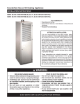
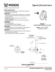
1
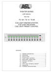
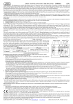
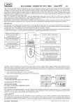
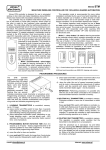
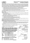
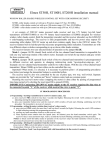
U4H FOUR CHANNEL WIRELESS CONTROL RECEIVER & SETS WITH DYNAMIC CODE Universal four relay outputs receiver (U4HR)* and sets (U4HS & U4HSL)* are designed for use in alarm systems and remote control applications. The sets consist of U4H receiver and one four buttons hand held remote control transmitter. The devices use KEELOQ® dynamic coding technology and the receiver operates with all Elmes made 434 MHz radio band transmitters and wireless detectors including specific RP501 transmitter made by Elmes Electronic. Receiver operation Activating transmitter stored in receiver memory sets on respective relay output and LED indication in the receiver. Depending on programmed operating mode, the output may be set on temporarily for earlier programmed time period (monostable mode) or set on until next signal is received from transmitter in on/off mode (bistable mode). These two basic output modes relate to U4H receiver operation with most transmitters. However, in operation with Elmes RP501 transmitter in its radio relay mode (mode 3) or CTX3H and CTX4H wireless magnet detectors operating in open/close detection mode, the receiver relay output set on state lasts until set off signal is received, regardless of the receiver output programmed operating mode. Description of jumpers JP1...JP5 JP1 and JP2 setting define possible signal output S (OC type) operation modes, as shown in the cross table below: Jumper setting JP2 ON JP2 OFF Two pulses shorting to ground are generated at output S on any relay set on, Output S is permanently shorted to ground on any JP1 ON one pulse – on any relay set off transmitter low battery signal received (no indic. pulses are generated on outputs set on/off ) As above, but shorting pulses are related to channel 1 output only JP1 OFF JP3 – shorting/pause timing of pulses at output S (jumper ON – 0.25/0.25s, jumper OFF – 0.5/0.5s). JP4 – setting this jumper OFF allows simple alarm control panel function of U4H receiver – for detailed description see wireless control panel section below. JP5 – setting this jumper OFF switches operating mode of U4H receiver and it’s all outputs to user controlled real time operation with programmable set off delay. In this mode output of the receiver is set on for as long as its respective button is kept pressed in remote control transmitter. The setting off of the output is made with transmitter button release, after a programmable short time delay needed to avoid possible interruptions in operation of the output due to interferences caused by e.g. electric motors. Precise programming of this short delay time is facilitated by build in 8-fold longer programming time of that really needed. Example: to obtain 0.5s set off delay after transmitter button release, the programmed delay time in pt 2 step 4 of programming procedures should be 4s. IMPORTANT: Delay time programming facilitation is active only with JP5 set OFF and U4H memory of remote control transmitters is limited to 20 in this mode. 12V LED indication – lights green on all outputs off, lights red on any output on, blinks when transmitter low battery warning is on in any channel. Low battery warning. This function is supported for all Elmes remotes and transmitters PTX50, GBX, CTX and RP. Blinking receiver’s LED indicates detected low battery in one of the transmitters. Number of blinks in a series indicates channel number where low battery is detected. Additionally, output S is shorted to ground if jumper JP2 is set off. Low battery warning sets off after battery is replaced and transmitter activated. _ + Anit-sabotage protection (TAMPER). Opening of the U4H receiver’s housing is detected as TAMPER circuit break-in. OUTPUTS Buzzer + D2 D1 S + D3 _ NC NO NC NO NC NO tamper NC output Manufacturer: Elmes Elektronik, 54-611 Wroclaw, Avicenny Str. 2, PL. NC Specification Design for use with 433,92MHz band transmitters and wireless detectors. Four galvanic separated relay outputs rated 1A/30VDC or 0,5A/125VAC. Outputs set on timing in monostable (pulse) mode 0.25s up to 4h. Receiver power supply: 10-15VDC with 20mA current at standby and 120mA max. Signal output S rated 1A/60V max. WARNING! Signal output S (open collector type) is shorted to receiver ground when activated and must not be directly connected to (+) of power supply. D4 NO Installation (as shown on fig.1) U4H receiver is designed to operate in ambient temperature range from -20 to +55°C, protected from direct atmospheric conditions. Place of installation should be dry and away from any electromagnetic power lines, radio transmitters, metal screening and other devices that may cause interference and reduce operation range. Practical operating range test using optional Elmes RFM4 monitor is recommended prior to firm installation. Receiver’s wire antenna should be let loose downwards and must not be glued to any surface. Receiver’s relay outputs standby mode (NO-normally opened or NCnormally closed) is selected by jumpers, individually for each output. Receiver's board Fig.1 Phone: 0048717845961, 0048717845962, Fax: 0048717845963 Manufacturer’s Limited Warranty: this product carries 24 months manufacturer’s warranty as from the date of purchase. The warranty is limited to the replacement of faulty original parts or repair defects of improper manufacture. Damage, faulty use or improper handling by the user or installer as well as any changes in product’s hardware or software caused by the user violets the warranty and all due repair costs will be charged. Elmes Electronic shall not bear liability for any personal or material damage resulting from any of its products direct, indirect or partial failure to operate properly. KEELOQ® is a registered trademark of Microchip Technology Inc., USA. U4H RECEIVER IN WIRELESS CONTROL PANEL MODE When JP4 is set OFF the U4H receiver operates in wireless control panel mode (see Fig.2 – for connections example) featuring the following specifications: Eight wireless alarm zones for up to 112 Elmes wireless detectors and remote control transmitters. Arming and disarming by Elmes remote control transmitter. Alarm events memory (also on power cut off) with alarm zone indicated by LED. Non-volatile memory of system status armed/disarmed on power supply restore after cut off. Wired siren Pow er Siren Strobe supply Panic alarm function by hold pressed remote control transmitter button for more than 2s. 12VDC Number of alarms occurring in armed mode limited to five. + Four relay outputs NO/NC type (jumper selected) with the following functions: + - + - output D1 – armed/disarmed signalling, - output D2 any application, example: set on/off by the use of 2nd button of transmitter, - output D3 – optical and/or audible alarm signalling, _ D4 D3 D2 D1 S - output D4 24h alarm zone (detector’s TAMPER alarm or panic button function). Siren/buzzer control output OC type (open collector - 1A/60V) active on: - system arming (one pulse), disarming (two pulses), - indication of occurred alarm event by 6 short pulses on disarming of the system, Bicolour LED featuring system warnings and indication, as follows: - system armed - lights red, disarmed – lights green, - alarm event memory - flashes red when system is armed, and up to 2 minutes after disarming, - transmitter’s low battery warning - flashes green when the system is disarmed where Fig.2 number of flashes (1..8) indicates alarm event zone number, or detector’s low battery zone. + For latest instructions and product data please see: www.elmes.pl or write to: [email protected] Elmes Electronic 08 .2014 All rights reserved. Steps to follow in designing of a simple wireless alarm system with the use of U4H receiver as control panel: 1. Set jumper JP4 off. Delete memory of the receiver according to pt 4 of programming procedures. 2. Learn wireless detectors to the receiver. The sequence of detectors learning to U4H receiver corresponds to alarm zone number it is learned. The first detector is learned to zone 1, the second to zone 2, the eighth to zone 8 while the ninth detector is learned to zone 1. Up to 112 wireless detectors can be learned to 8 available zones. 3. Learn one button remote control transmitters to channel 1 that will be used for arming and disarming of the system. Two buttons hand transmitters can also arm/disarm the system: one button is used for arming/disarming and the other for controlling any other wireless appliance connected to output 2, for example control of garage gate open/close. When learning two button remotes use second button and learn to output D2 of the receiver. Button 1 of the remote will be learned to output D1 automatically. 4. Program D1 output mode to on/off (bistable) and required alarming time at outputs D3 and D4 (up to 4 hours). 5. Connect power supply and alarming devices as shown on schematic diagram Fig.2. PROGRAMMING PROCEDURES Programming is made with U4H receiver front panel taken off and the use of programming PRG switch on board. 1. LEARNING REMOTES, TRANSMITTERS AND WIRELESS DETECTORS TO RECEIVER’S MEMORY (up to 112 max. and up to 20 with JP5 off): IMPORTANT: Before entering this programming mode it is recommended to determine which remote control transmitter button or which RP501 transmitter’s input should control required output of the receiver. It is important, as programming remote’s button or RP501 transmitter input other than 1st (i.e. 2 nd, 3rd or 4th) to control receiver’s output other than 1st (i.e. 2nd, 3rd or 4th) precedeing button/s or RP501 transmitter input/s are automatically programmed to preceding control outputs of the U4H receiver (see examples 1-3 below). Only the first button of multi button remote or the first input of four input RP501 transmitter can be programmed to any U4H receiver control output without automatic programming any other transmitter control channel to the receiver. Step 1. Press receiver's PRG switch for less than 2 seconds. Receiver’s LED switches to red and D1 output LED illuminates. Step 2. By short pressing steps with PRG switch (less than 2 seconds each) select required receiver’s output (D1...D4) to control. Step 3. Press PRG switch for more than 2 seconds until the main receiver LED changes to green, Step 4. Now, depending on type of transmitter to be learned proceed as follows: - Remote control transmitters – double press transmitter’s button. With multi channel remotes double press button number respective to number of receiver outputs required to be controlled, as in examples below: Example 1: double pressing button 4 of remote transmitter CH4H with receiver’s output D4 selected at step 2 above will learn all four buttons to the receiver. Button 4 controls output D4, button 3 controls output D3, button 2 controls output D2 and button 1 controls output D1. Example 2: double pressing button 3 of remote transmitter CH4H with receiver output D4 selected at step 2 above will learn first three buttons to the receiver. Button 3 controls output D4, button 2 controls output D3, button 1 controls output D2. Button 4 of this transmitter will not be active for this receiver. Example 3: double pressing button 4 of hand transmitter CH4H with receiver output D2 selected at step 2 above will learn two last buttons to the receiver. Button 4 controls output D2 and button 3 controls output D1. Buttons 1 and 2 of this transmitter will not be active for this receiver. Remotes buttons layout in U4HS & U4HSL sets buttons layout - Wireless detectors PTX50, CTX3H, CTX4H, and GBX – activate transmissions as described in detectors’ manuals. Except for detector GBX, all other detectors’ boxes must be closed! - RP501 transmitter – select required mode of operation in RP501 transmitter and activate transmission by disconnecting any of its inputs shorted to ground. Receiver’s LED blinking green slowly indicates end of procedure. LED’s blinking fast red indicates programming error. Repeat procedure as above. 2. SETTING RECEIVER RELAY OUTPUTS MODE TO PULSE OPERATION (monostable mode): Step 1. Press receiver's PRG switch for more than 2 and less than 8 seconds, LED switches to red and again to green indicating entering this programming mode (output D1 LED is on and ready for programming set on time). Step 2. By short pressing steps with PRG switch (less than 2 seconds each) select required output (D1...D4) to control. Step 3. Press PRG switch for more than 2 seconds until main receiver’s LED switches to red. Step 4. Press PRG switch and the receiver’s LED switches to green indicating start of the output set on time count. When required set on time has lapsed (up to 4 hours maximum) press the PRG switch again to stop the procedure – LED switches to red. After a short while main LED blinking green confirms end of the procedure. 3. SETTING RECEIVER RELAY OUTPUTS TO ON/OFF (LATCHED) OPERATION (bistable mode): Steps 1,2,3. Follow programming steps exactly the same way as in procedure 2 above. Step 4. Triple (3 x) press shortly PRG switch with less than two seconds intervals. After a short while main LED blinking green confirms end of the procedure. 4. DELETING ALL REMOTES, DETECTORS AND OTHER TRANSMITTERS FROM RECEIVER MEMORY: Hold pressed receiver PRG switch for more than 8 seconds. Initially, the receiver’s LED switches to red and after two seconds to green. After next six seconds the LED starts blinking. Release the switch now. Transmitter memory of the receiver is now deleted but outputs programmed mode of operation remains unchanged. The receiver does not respond to signals sent from any transmitters. To learn new transmitter(s) to the receiver's memory follow procedure 1 above. To change outputs operating mode follow procedure 2 or 3 above. 5. DELETING SINGLE TRANSMITTER FROM RECEIVER MEMORY: Except for RP501 transmitters, it is possible to delete any other single transmitter from receiver’s memory under condition that the transmitter to be deleted is in our possession. This tricky procedure requires performing steps 1,2,3 of transmitter’s learning procedure 1 above, whereas two succeeding transmissions at step 4 (double pressing transmitter’s button) to be performed in the following way: first transmission must be sent from the transmitter to be deleted and second transmission from any other transmitter (e.g. by pressing other button in multi button remote control transmitters). Receiver LED blinking red will indicate programming error – in this case meaning that the transmitter is deleted. The receiver does not respond to signals sent from deleted transmitter. NOTE! Programming errors and no activity longer than 30 seconds are indicated by fast blinking LED in red followed by programming mode set off. (*) Product ordering, marking and labelling description: U4HR - universal remote control receiver U4H with four relay outputs. U4HS - universal remote control set consisting of U4H receiver and one small hand held transmitter powered by 12V battery type 23A with up to 300 meters operating range in open field. U4HSL - universal remote control set consisting of U4H receiver and one hand held remote control transmitter powered by 9V battery with up to 600 meters operating range in open field. For latest instructions and product data please see: www.elmes.pl or write to: [email protected] Elmes Electronic 08 .2014 All rights reserved.